Performance Evaluation of Carbide Tool on Turning of Alloy
Steel
Chhaya Patil1, Niyati Raut2
1
Mechanical Department,VIVA Institute of Technology, Virar (E),Maharashtra, India
2
Mechanical Department,VIVA Institute of Technology, Virar (E),Maharashtra, India
Abstract
The main objective of today's manufacturing industries is to produce low cost, high quality products in short time. The selection of optimal cutting parameters is a very important issue for every machining process in order to enhance the quality of machining products and reduce the machining costs. This paper investigates the machining of alloy steel to find optimal parameters for CNC turning process. The Taguchi method is used to formulate the experimental layout, to analysis the effect of each parameter on the machining characteristics and to predict the optimal choice for each turning parameters such as Speed, Feed and Depth of cut. It is found that these parameters have a significant influence on machining characteristics such as Material removal rate (MRR) and Surface roughness (SR). The Analysis of Variance (ANOVA) is used to study the performance characteristics in turning operation.
Keywords: CNC Turning, Alloy Steel, ANOVA, Carbide Tool,
Material Removal Rate, Surface Roughness
1. Introduction
Metal cutting is one of the vital processes and widely used manufacturing processes in engineering industries. Highly competitive market requires high quality products at minimum cost. Products are manufactured by the transformation of raw materials. Industries in which the cost of raw material is a big percentage of the cost of finished goods, higher productivity can be achieved through proper selection and use of the materials. To improve productivity with good quality of the machined parts is the main challenges of metal industry; there has been more concern about monitoring all aspects of the machining process. Surface finish is an important parameter in manufacturing engineering and it can influence the performance of of mechanical parts and the production costs. The ratio of costs and quality of products in each production phase has to be monitored and quick corrective actions have to be taken in case of deviation from desired output .Surface roughness measurement presents an important task in many
engineering applications. Many life attributes can be also determined by how well the surface finish is maintained. Turning is a very important machining process in which a single point cutting tool removes unwanted material from the surface of a rotating cylindrical work piece. The cutting tool is fed linearly in a direction parallel to the axis of rotation.
Carbide cutting tools are very popular in metal cutting industry for the cutting of various hard materials such as, alloy steels, die steels, high speed steels, bearing steels, white cast iron and graphite cast iron. In the past few decades there had been great advancements in the development of these cutting tools. Coating is also used on cutting tools to provide improved lubrication at the tool/chip and tool/work piece interfaces and to reduce friction, and to reduce the temperatures at the cutting edge. During machining, coated carbide tools ensure higher wear resistance, lower heat generation and lower cutting forces, thus enabling them to perform better at higher cutting conditions than their uncoated counterparts. The use of coated tools are becoming increasingly demanding among the other tool materials. More than 40% of all cutting tools are coated in modern industry today.
Surface properties such as roughness are critical to the functional ability of machine components. Increased understanding of the surface generation mechanisms can be used to optimize machining process and to improve functional ability of the component. Numerous investigators have been conducted to determine the effect of parameters such as feed rate, tool nose radius, cutting speed and depth of cut on surface roughness in hard turning operation. The surface roughness decreases with increasing nose radius. Large nose radius tools have produced better surface finish than small nose radius tools.
of cut and cutting environment. Experimental works have been carried out on the above mentioned parameters.
2. Problem Statement
The current problem addressed by industry is surface finish obtained while machining. The industry requires machining of component in minimum time maintaining its accuracy and surface finish. This is where the main problem starts, which leads to high machining cost, high machining time, increases labour cost, etc.
Product that is machined today for shaft must have excellent accuracy with good surface quality, since market leadership totally depends on the low cost with high quality. The high speed machining technology and new modern machine tool permit an easy achievement of these requirements but only using the high speed machining is not enough to optimize quality in manufacturing sector because of much complexity in its precise control which makes it difficult to employ by manufacturer of shaft.
EN19 steel has good machinability property with high tensile strength and its composition of material. It also offers excellent polishing and good surface finish. EN19 steel which is used for Axle shafts, Crank shafts, Gears, Connecting rods, Studs, Bolts, Propeller shaft joint. Suitable for heat treated parts where high tensile and impact are required along with high endurance bending strength. machining as the accuracy and quality of surface finish is very important criteria in molds. Thus the correct selection of cutting parameters generates optimum conditions during the machining of shafts and becomes the main exigency of machining industry. Number of cutting tool (inserts) are available for turning operation as per workpiece material and its properties. In this research work I have used EN 19 material which is turned by VCMT 160404 insert to study the surface roughness and material removal rate for above combination.
3. MACHINE ,MATERIALS AND
METHODS
3.1 Machine used
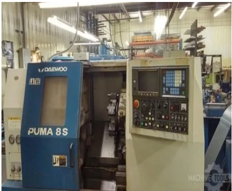
Turning operation was conducted on CNC lathe centre (DAEWOO PUMA with FANUC computer control) having maximum spindle speed 4000 rpm shown in Fig 3.1
Fig 3.1 CNC lathe centre
3.2 Workpiece and Cutting tool
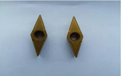
The workpiece material is EN 19 alloy steel.The chemical compositon and physical properties of workpiece material is shown in Tables3.1 and 3.2 below. EN19 steel has good machinability property with high tensile strength and its composition of material. It also offers excellent polishing and good surface finish. EN19 steel which is used for Axle shafts, Crank shafts, Gears, Connecting rods, Studs, Bolts, Propeller shaft joint. Suitable for heat treated parts where high tensile and impact are required along with high endurance bending strength. The machining process was performed using AVJNL 2525M16 tool holder and VCMT 160404 titanium nitride (TiN) coated
carbide insert. The tool holder and tool is shown in figure 3.2 and figure 3.3 respectively.
The specification of tool holder are as follows : Model : AVJNL 2525M16
Manufactured by : sandhogtools Material : carbon steel
Direction : left hand
Square shank : 25mm x 25 mm
Suitable for ISO code carbide insert :VCMT 160404
Table 3.1 : Mechanical properties of EN19 Steel
Tensile strength
700-800 (N/mm2)
Yield stress
495 (N/mm2)
Impact strength (izod)
34 min
Proof stress 0.2 %
480 (N/mm2)
Table3.2 : Chemical composition of EN19 Steel
Fig 3.2 : Tool Holder
Fig 3.3 : VCMT 160404 tool insert
3.3 Taguchi Methodology
a. System Design: It determines vital design factors and appropriate working levels. In this experiment there are many different parameters available so, we would select only important factors which will affect our output and will help us to get good results.
b. Parameter Design: Its objective is to conduct experiment and identify optimal design factors to improve performance and reduce variation. As we have designed system we need to select an orthogonal array that will lead to optimal parameter design. Thus by
observing the system design we select a standard orthogonal array i.e. L9 (3^4).
c. Tolerance Design: Its objective is to determine optimal settings identified during parameter design process. This leads to robust design in which the designed process delivers the target value. Thus after using the experimental data we apply the Taguchi Design and obtain Signal to Noise ratio which helps us to find target value.
3.4 ANOVA Analysis
The terminology of ANOVA is largely from the statistical design of experiments. The experimenter adjusts factor and measures responses in an attempt to determine an effect. Factors are assigned to experimental units by a combination of randomization and blocking to ensure the validity of the results. Analysis of Variance is a mathematical technique which breaks total variation down in to accountable sources; total variation is decomposed into its appropriate components. Once all the parameters have been decided and level values are set, experimentation is performed. The results are tabulated section wise. After the experimental results have been obtained, analysis of the results is carried out analytically as well as graphically. For graphical analysis of the experimental results plots, showing effects of all the factors upon responses, are generated in MINITAB17. Then ANOVA of the experimental data has been done to calculate the contribution of each factor in each response.
4 Experimental Procedure and Analysis
The experiment is designed as per Taguchi Design Approach. This approach starts with following three stages.
i. System Design: In this experiment we would select only important factors which will affect our output and will help us to get good results. The Process parameters that are to be selected are shown in Table 4.1.
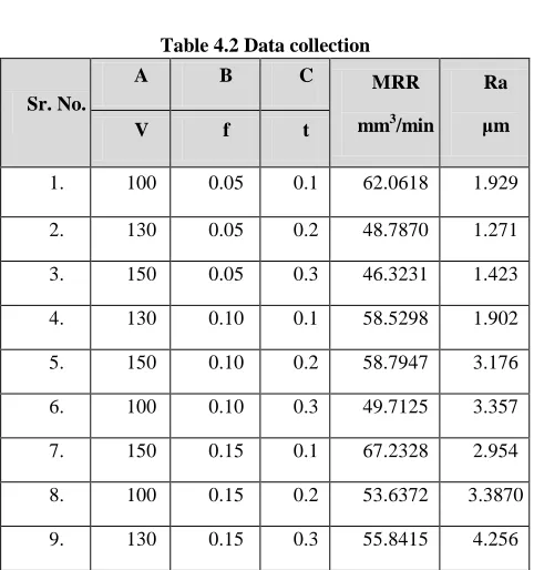
ii. Parameter Design: Thus by observing the system design we select a Taguchi standard orthogonal array i.e. L9 orthogonal array. According to this array we are going to record data which is shown in Table 4.2.
Carbon
0.07-0.15 %
Silicon
0.4 % max
manganese
0.9-1.3 %
Suipher
0.2-.0.3%
Phosphorus
0.07% max
Table 4.1 System Design for EN 19 Alloy Steel
Table 4.2 Data collection Sr. No.
A B C MRR
mm3/min
Ra μm
V f t
1. 100 0.05 0.1 62.0618 1.929
2. 130 0.05 0.2 48.7870 1.271
3. 150 0.05 0.3 46.3231 1.423
4. 130 0.10 0.1 58.5298 1.902
5. 150 0.10 0.2 58.7947 3.176
6. 100 0.10 0.3 49.7125 3.357
7. 150 0.15 0.1 67.2328 2.954
8. 100 0.15 0.2 53.6372 3.3870
9. 130 0.15 0.3 55.8415 4.256
5 Results
By implementing Taguchi method for the above experiment we have found optimal values for optimal setting.
By using main effect plots relationship between various parameters can be simplified as shown below.
0.15 0.10 0.05 3.5
3.0
2.5
2.0
1.5
0.3 0.2
0.1 100 130 150
Feed (mm/rev)
M
ea
n
Depth of cut (mm) Cutting speed (m/min)
Main Effects Plot for Ra (µm)
Data Means
Fig. 5.1 Effects of Process Parameters on Surface Roughness
0.15 0.10 0.05 -3
-4
-5
-6
-7
-8
-9
-10
-11
0.3 0.2
0.1 100 130 150
Feed (mm/rev)
M
ea
n
of
S
N
r
at
io
s
Depth of cut (mm) Cutting speed (m/min)
Main Effects Plot for SN ratios
Data Means
Signal-to-noise: Smaller is better
Fig. 5.2 S/N Ratio Vs Process Parameters for Surface Roughness
From Figure 4.5 and Figure 4.6 the various effects of process parameters observed are shown below:
a.Effects of Feed on Surface Roughness: It is observed that Surface Roughness decreases as feed decreases from 0.15 mm/rev to 0.05 mm/rev and from S/N ratio graph it is observed that values decreases as the feed increases gradually.
b.Effects of depth of cut on Surface Roughness: It observed that as Surface Roughness increases from 2.2 to 3 μm as depth of cut increases from 0.1 mm to 0.3 mm
c.Effects of cutting speed on Surface Roughness: It is observe that surface roughness decreases as cutting speed increases from 100 to 200 m/min
Sr.
No. INPUT Parameters
Cutting speed (m/min)
(V)
Feed (mm/rev)
(f)
Depth of Cut (mm) (t)
Factors A B C
1. Level- 1 100 0.05 0.1
2. Level- 2 130 0.10 0.2
0.15 0.10 0.05 64
62
60
58
56
54
52
50
0.3 0.2
0.1 100 130 150
Feed (mm/rev)
M
ea
n
Depth of cut (mm) Cutting speed (m/min)
Main Effects Plot for MRR (mm3/sec) Data Means
Fig. 5.3 Effects of Process Parameters on MRR
0.15 0.10 0.05 36.0
35.5
35.0
34.5
34.0
0.3 0.2
0.1 100 130 150
Feed (mm/rev)
M
ea
n
of
S
N
r
at
io
s
Depth of cut (mm) Cutting speed (m/min)
Main Effects Plot for SN ratios
Data Means
Signal-to-noise: Larger is better
Fig. 5.4 S/N Ratio Vs Process Parameters for Surface Roughness
a.Effects of Feed on Material Removal Rate: It is observed that Material Removal Rate increases as feed increases from 0.05 mm/rev to 0.15 mm/rev.
b.Effects of Depth of cut on Material Removal Rate: It is observed that as Material Removal Rate as depth of cut decreases from 0.3 mm to 0.1 mm
c.Effects of cutting speed of Cut on Material Removal Rate: It is observe that MRR is decreases as cutting speed increases from 100 to 300 m/min and MRR is increases as cutting speed increases from 130 to 150 m/min
6. Confirmation Test
The final step of the Taguchi method is the confirmation experiments conducted for examining the quality characteristics. The model used in the confirmation tests is defined with the total effect generated by the control factors. Three confirmation experiments are performed
Confirmation experiments for VCMT 160404 insert
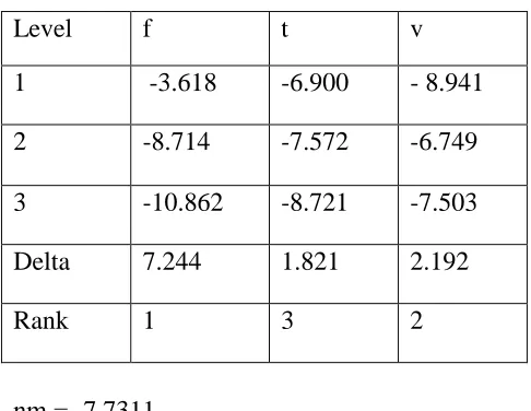
From mean of each level of every factor we will construct response table for surface roughness (SR) which are given below :
Response table for SR
Table 6.1 : Response table for SR
Level
f
t
v
1
-3.618
-6.900
- 8.941
2
-8.714
-7.572
-6.749
3
-10.862
-8.721
-7.503
Delta
7.244
1.821
2.192
Rank
1
3
2
ɳɱ = -7.7311
From above main effect plot of SR we can conclude the optimum condition for SR is: (f1-t2-V2)
=-7.7311+(-3.618+7.7311)+(-6.900+7.7311)+(- 6.749+7.7311) = -1.8048
=
𝑦𝑦
op t= 1.2309 (Theorotical)
𝑦𝑦𝑜𝑜𝑝𝑝𝑡𝑡= 1.271(Experimental)
Response table for MRR
Table 6.2 : Response table for MRR
Level
f
t
v
1
34.31
35.92
34.79
2
34.89
34.58
34.68
3
35.36
34.06
35.08
Delta
1.05
1.86
0.40
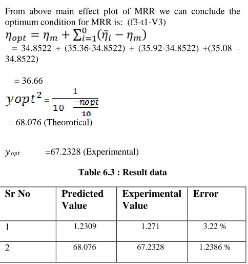
ɳɱ = 34.8522
From above main effect plot of MRR we can conclude the optimum condition for MRR is: (f3-t1-V3)
= 34.8522 + (35.36-34.8522) + (35.92-34.8522) +(35.08 – 34.8522)
= 36.66
=
= 68.076 (Theorotical)
𝑦𝑦𝑜𝑜𝑝𝑝𝑡𝑡
=67.2328 (Experimental)
Table 6.3 : Result data
Sr No Predicted
Value
Experimental Value
Error
1 1.2309 1.271 3.22 %
2 68.076 67.2328 1.2386 %
From analysis of table 6.3 it is observed that the calculated error is small. The error between experimental and predicted values of SR and MRR are lies within ±10 %.this confirms excellent reproducibility of the experimental conclusion.
7. Conclusion
In the present study, the surface roughness and material removal rate were analysed to investigate the effect of cutting conditions during turning of EN 19 alloy steel using TiN coated carbide insert. After selecting the factors and response variables the levels for factors are selected through literatute review and studying the capacity of machine, results of the experimentation has been analyzed and from those result final experimentation was carried out by using Taguchi design. A graph for effect of various input variables upon output parameters have been studied and discussed using ANOVA. Also optimum combination of input variables has been determined which will give the best results for output parameters. L9 orthogonal array has been selected with nine experimental runs.Based on the experimental results the following conclusion are drawn within the range of process parameter selected:
Higher MRR (67.2328 mm3/min) is obtained at a high feed rate 0.15 mm/rev, lower depth of cut 0.1 mm and at high cutting speed 150 m/min.
Lower surface roughness 1.271 µm is obtained at lower feed rate 0.05 mm/rev , depth of cut 0.2 mm and cutting speed 130 m/min.
Acknowledgments
I acknowledge with deep sense of gratitude and humility, the inspiring help and guidance rendered by my supervisor, Prof. Niyati Raut, Professor & Head in Mechanical Engineering Department, Viva Institute of Technology (Virar), for their interest and encouragement throughout the course of this research effort. Their deep insights into the problem and ability to provide guidance and solutions have been of immense value in improving the quality of my research work at all stages. I am also thankful to Dr. Arun Kumar, Professor and Principal, Viva Institute of Technology (Virar), for their encouragement and moral supports. and all other authors for their guidance on such a good topic
References
[1] Motorcu, A. R., Isik, Y., Kus, A., & Cakir, M. C. (2016). Analysis of the Cutting Temperature and Surface Roughness during the Orthogonal Machining of Aisi 4140 Alloy Steel via the Taguchi Method.Analysis,343, 351.
[2] Lavish Sharma, IIJai Prakash Sharma, IIINitin Sharma
“Optimization of Cutting Parameters for Surface Roughness in Turning of Alloy Steel EN 47” International Journal of Advanced Research in Mechanical Engineering & Technology (IJARMET) Vol. 2, Issue 4(Oct. - Dec. 2016) ISSN: 2454-4736 (Online) ISSN : 2454-8723 (Print)
[3] Singh, Devendra, Vimanyu Chadha, and Ranganath M. Singari. "Effect of nose radius on surface roughness during CNC turning using response surface methodology." International Journal of Recent Advances in Mechanical Engineering 5 (2016): 31-45.
[5] Arulkirubakaran, D., V. Senthilkumar, and Vijay Kumawat. "Effect of micro-textured tools on machining of Ti–6Al–4V alloy: an experimental and numerical approach." International Journal of Refractory Metals and Hard Materials 54 (2016): 165-177.
[6] Ånmark, Niclas, and Thomas Björk. "Tool Wear in Soft Part Turning of High Performance Steel." Procedia CIRP46 (2016): 484-487.
[7] Zheng, FengLian Sun, and ShuCai Yang. "YiHang Fan, ZhaoPeng Hao, MinLi." Int J Adv Manuf Technol69 (2013): 2659-2667.
[8] P.Surulimani1, A.Karthikraja2, V.Sivaganesan3, J.Gowthaman4, M.Yojiith Optimization of CNC Turning Parameters on EN36B Steel Using Taguchi Method International Journal of Innovative Research in Science, Engineering and Technology Vol. 5, Issue 2, February 2016 ISSN(Online): 2319-8753 ISSN (Print) : 2347-6710
[9] Kim, Dong Min, et al. "Influence of a micropatterned insert on characteristics of the tool–workpiece interface in a hard turning process."Journal of Materials Processing Technology229 (2016): 160-171.
[10]Lata, Surabhi, et al. "Optimizing Process Parameters for CNC Turned Parts Using Taguchi’s Optimization Technique.
[11]Ottersbach, Michael, and Wei Zhao. "Experimental Investigations on the Machinability of Tungsten Carbides in Orthogonal Cutting with Diamond-coated Tools." Procedia CIRP46 (2016): 416-419.
[12]Uhlmann, E., et al. "Hard Turning of Hot Work and Cold Work Steels with HiPIMS and DCMS TiAlN Coated Carbide Inserts."Procedia CIRP46 (2016): 591-594. [13]Dureja, J. S., et al. "Performance evaluation of coated
carbide tool in machining of stainless steel (AISI 202) under minimum quantity lubrication (MQL)."International Journal of Precision Engineering and Manufacturing-Green Technology2.2 (2015): 123129.
[14]Suresh, R., S. Basavarajappa, and V. N. Gaitonde. "Experimental studies on the performance of multilayer coated carbide tool in hard turning of high strength low alloy steel."Journal of Materials Research30.20 (2015): 3056-3064
[15] Jijo anatomy, Design of Experiment, Elsevier Science & Technology Books, October 2003.
First Author: I am currently in my final year of Masters of Engineering in Mechanical Engineering (Manufacturing Systems Engineering) at VIVA Institute of Technology. I have completed my Bachelor of Engineering in Mechanical Engineering from Government college of Engineering Jalgaon and Diploma in Mechanical from Government Polytechnic Mumbai. I currently work as Leturer in Theem college of Engineering.