Zigbee Based Remote Control Automatic
Street Light System
I.VIJAYALAKSHMI Department Of E.C.E
MADHIRA INSTITUTE OF TECHNOLOGY & SCIENCES. Kodad, Nalgonda district,
Telangana-508206, INDIA
T BHAVANI
Assistant professor Department Of E.C.E
MADHIRA INSTITUTE OF TECHNOLOGY & SCIENCES. Kodad, Nalgonda district,
Telangana-508206, INDIA
Abstract— the main aim is to provide remote-control system
can optimize management and efficiency of street lighting systems. It uses Zigbee-based wireless devices which enable more efficient street Lamp-system management, thanks to an advanced interface and control architecture. It uses a sensor combination to control and guarantee the desired system parameters; the information is Transferred point by point using Zigbee transmitters and receivers and is sent to a control terminal used to check the state of the street lamps and to take appropriate measures in case of failure.
Index Terms - Automation, control system, lighting system, sensors, wireless networks, Zigbee.
I. INTRODUCTION
The street lighting system is an essential factor in public sectors. So we need to design and implement solar based street lighting system with the help of Zigbee network of devices and the newly proposed street lighting system offer higher efficiency and considerable savings that can be achieved by using high all the day. But the newly proposed system is a good efficient LED technology. Early days, the street lighting systems are controlled manually. So there was much more power consumption if we forgot to switch off the light means that will be glowing power saver and that will be automatically controlled by the base station. This project contains monitoring stations and one base station.
The monitoring station located in each lamp post consists of several modules such as PIR sensor, the LDR sensor, and an emergency switch. These devices work together and transfer all of the information to a microcontroller which processes the data and automatically sets the appropriate
action. The PIR Sensor will helpful to detect the presence of human. Whenever the presence of human will be detected the next step to measure the intensity of light. For that purpose we are using an LDR sensor. A light sensor can measure the brightness of the sunlight and provides information. In day time intensity of light will be high because of negative temperature coefficient so no need of lighting system. When the intensity of light becomes low that time necessary of the street lighting. So the information will pass to the base station
via Zigbee. From the base station a message pass to the microcontroller to glow the street light according to the intensity of light.
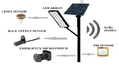
Fig1 Schematic image of the system
developments. In many cases, this is related to the plant administrators who have not completed the return of the expenses derived from the construction of existing facilities yet. However, the recent increasing pressure related to the raw material Costs and the greater social sensitivity to environmental issues are leading manufacturers to develop new techniques and technologies which allow significant cost savings and a greater respect for the environment. We can find three possible solutions to these problems.
II. METHODOLOGY
Fig. 1 shows the conceptual scheme of the proposed system. It consists of a group of observation stations on the
street (one station for each lamp post) and a base station typically placed in a building located nearby. It is a modular system, easily extendable.
The measuring stations monitor the street conditions and the intensity of sunlight and, based on them, they decide to turn the lamps on or off . The conditions depend on the pattern of the street where the lights are located and on the solar irradiation at a given point of the street, with frequent changes, depending on weather conditions, season, geographical location, and many other factors.
`Fig2. Schematic image of an on-street station
For these reasons, we decided to make each lamp completely Independent in the management of its own lighting. The on-street station also checks if the lamp is properly working and sends the information through the wireless network to the base station for processing data. If any malfunction is detected, the service engineer is informed through a graphical interface and can perform corrective actions.
A. Sensing
The purpose of this unit is to detect (sense) all the parameters desired using a collection of sensors that were chosen carefully to a chive the best performance. Digital sensors will give a digital output suitable for the arm (digital only input), while analog sensors will need analog to digital conversion.
B. Monitoring Stations
The monitoring station located in each lamp post consists of several modules: the presence sensor, the light sensor, the failure sensor, and an emergency switch. These devices work together and transfer all of the information to a microcontroller which processes the data and automatically sets the appropriate course of action. A priority in the transmission of information is assigned to each sensor, for
example, the emergency switch takes precedence over any other device.
1) Presence Sensor: The task of the presence sensor is to identify the passage of a vehicle or pedestrian, giving an input to turn on a lamp or a group of lamps. This function depends on the pattern of the street; in case of a street without crossroads, a single sensor is sufficient (or one at each end in case of a two-way street),while for a street requiring more precise control, a solution with multiple presence detectors is necessary.
This feature enables switching on the lamps only when necessary, avoiding a waste of energy. The main challenge with such a sensor is its correct placement. The sensor should be placed at an optimal height, not too low (i.e., to avoid any erroneous detection of small animals) nor too high (for example, to avoid failure to detect children). A study of the sensor placement enables deciding the optimal height according to the user needs and considering the specific environment in which the system will work. We discovered that in field tests, the SE-10 PIR motion sensor offers good performance and is quite affordable.
2) Light Sensor: A light sensor can measure the brightness of the sunlight and provides information. The purpose of this measurement is to ensure a minimum level of illumination of the street, as required by regulations the sensor must have high sensitivity in the visible spectrum, providing a photocurrent high enough for low light luminance levels. For this reason, the phototransistor
during daylight and the sensor incorrectly detects a fault, but the microcontroller does not report the malfunction because of additional logic functions).
4) Connect to sensors Each of the system's sensors is connected to the ARM’s GPIO pins in different configurations The main concept of the wiring is that digital sensors are connected directly to the ARM’s GPIO, while analog sensors are connected to an analog to digital converter, which in turn is directly connected to the ARM.
5) Software Design Before writing the code for the system, several software dependencies must be installed. These dependencies add more functionality to the use of Python on the ARM and make the software design process easier. For example, some dependencies allow Python to use the ARM’s interfaces or interface with its GPIO pins. The installation of dependencies requires internet connection. The code necessary to run the system was then installed on the ARM to operate the system
C. Zigbee Network
Zigbee is a wireless communication technology based on the IEEE802.15.4 standard for communication among multiple devices in a wireless personal-area network (WPAN). Zigbee is designed to be more affordable than other WPANs (such as, for example, Bluetooth) in terms of costs and, above all, energy consumption. A Zigbee personal-area network ( ZBPAN) consists of at least one coordinator, one (or more) end device(s) and, if required, one (or more) router(s). The network is created when a coordinator selects a channel and starts the communication, henceforth, a router or an end device can join the network. The typical distance of a Zigbee transmission range, depending on the environment conditions and the transmission power, shifts from tens to hundreds of meters, and the transmission power is deliberately kept as low as possible (in the order of a few mill watts) to maintain the
lowest energy consumption..
In the proposed system, the network is built to transfer information from the lamp posts to the base station control. Information is transferred point by point, from one lamppost to another where each lamp post has a unique address in the system. Each lamp post can only send the information to the nearest one, until the information reaches the base station. Thus, transmission power is limited to the required low value and the signals sent by the lampposts do not interfere with each other. In case of failure of one lamp, the chosen transmission distance between the lampposts ensures that the signal can reach the next operational lamp post without breaking the chain. The Zigbee wireless communication network has been implemented with the use of Digi-Max Stream radio-frequency modules called XBee modules, which are available in Standard and Pro versions (pin-to-pin compatible).
The Standard XBee modules have an operation range of tens of meters indoors and hundreds of meters outdoors, while the XBee Pro modules have a wider spread range in the order of hundreds of meters indoors and of about 1.5 km outdoors, because the Pro modules have higher transmission power, but imply higher consumption (about three times the consumption of the Standard version). The receiver has very high sensitivity and a low probability of receiving corrupted packets (less than 1%). The modules should be supplied by 3 V from a dc source; the current consumption is in the order of 50 mA (for XBee) and 150–200mA (for XBee PRO) in uplink and in the order of 50mA in downlink (identical for both versions); moreover, they support a sleep mode where consumption is less than 10 A. The XBee modules are distributed in three versions of antennas: with an on-chip antenna, a wire antenna, and with an integrated connector for an external antenna.
A. Hardware materials
1) Sensors
a) IR
A sensor also called detectors is a device that measures a quantifiable aspect and converts it into a signal which can be read by an observer or by an instrument.
IR led and IR sensor
IR led is used as source of infrared rays . It can be see ion two packages in 3mm and 5mm. for 3mm is better for less space and 5mm is long, here IR is nothing but a diode which is the sensitive for the radiation.
In this IR infrared tx and rx are called IR called as transmitter and receiver pair. they can get by any electronic component shop and the cost is also very less than 10rs we can the following figure how they are.
b) LDR
A photo resistor or Light Dependent Resistor or CdS Cell is a resistor whose resistance decreases with increasing incident light intensity. It can also be referred to as a photoconductor. A photo resistor is made of a high resistance semiconductor. If light falling on the device is of high enough frequency. Photons absorbed by the semiconductor give bound electrons enough energy to jump into the conduction band. The resulting free electron (and its hole partner) conduct electricity, thereby lowering resistance.
A photoelectric device can be either intrinsic or extrinsic. An intrinsic semiconductor has its own charge carriers and is not an efficient semiconductor, e.g. silicon. In intrinsic devices the only available electrons are in the valence band, and hence the photon must have enough energy to excite the electron across the entire band gap. Extrinsic devices have impurities, also called do pants, added whose ground state energy is closer to the conduction band; since the electrons don't have as far to jump, lower energy photons (i.e., longer wavelengths and lower frequencies) are sufficient to trigger the device. If a sample of silicon has some of its atoms replaced by phosphorus atoms (impurities), there will be extra electrons available for conduction. This is an example of an extrinsic semiconductor.
LDRs or Light Dependent Resistors are very useful especially in light/dark sensor circuits. Normally the resistance
of an LDR is very high, sometimes as high as 1,000,000 ohms, but when they are illuminated with light, the resistance drops dramatically.
Thus in this project, LDR plays an important role in switching on the lights based on the intensity of light i.e., if the intensity of light is more (during daytime) the lights will be in off condition. And if the intensity of light is less (during nights), the lights will be switched on.
1V.Circuit implementation and result
Developed streetlight system is composed of 2 different units, streetlight terminal at the transmitter side and control system at the receiver side. Among them, street light transmitter terminal are hardware based system and control system, works based on software. Figure 2 shows developed street light terminal at the transmitter side
As you can see, microcontroller, it simply converts all data parallel to serial form, also there is Zigbee module for transmitting and receiving purpose, its operating frequency is 2.4 GHz and operates at 3.3v and its data rate is 250 kbps..Communication between the microcontroller and Zigbee module was done with the help of UART cable.
All street lights ON automatically
All streetlights OFF automatically
Faulty light detection (One is ON, another is OFF)
V. CONCLUSION
This system provides an efficient and smart automatic streetlight control system with the Zigbee technology. The system can reduce energy consumption and maintenance costs and also helps to reduce crime activities up to certain limit. This streetlight control system helps in energy savings, detection of faulty lights and maintenance time and increase in life span of system
V1. REFERENCES
[1] M. A. D. Costa, G. H. Costa, A. S. dos Santos, L. Schuch, and J. R. Pinheiro, “A high efficiency autonomous street lighting system based on solar energy and LEDs,” in Proc. Power Electron. Conf., Brazil, Oct. 1, 2009, pp. 265–273.
[2] P.-Y. Chen, Y.-H. Liu, Y.-T. Yau, and H.-C. Lee, “Development of an energy efficient street light driving system,” in Proc. IEEE Int. Conf. Sustain. Energy Technol., Nov. 24–27, 2008, pp. 761–764.
[3] W. Yongqing, H. Chuncheng, Z. Suoliang, H. Yali, and W. Hong, “Design of solar LED street lamp automatic control circuit,” in Proc. Int. Conf. Energy Environment Technol., Oct. 16–18, 2009, vol. 1, pp. 90–93.
[4] W. Yue, S. Changhong, Z. Xianghong, and Y. Wei, “Design of new intelligent street light control system,” in Proc. 8th IEEE Int. Conf. Control Autom., Jun. 9–11, 2010, pp. 1423–1427.
[5] R. Caponetto, G. Dongola, L. Fortuna, N. Riscica, and D. Zufacchi, “Power consumption reduction in a remote controlled street lighting system,” in Proc. Int. Symp. Power Electron., Elect. Drives, Autom. Motion, Jun. 11–13, 2008, pp. 428–433.
[6] Y. Chen and Z. Liu, “Distributed intelligent city street lampmonitoring and control system based on wireless communication chip nRF401,” in Proc. Int. Conf. Netw. Security, Wireless Commun. Trusted Comput., Apr. 25–26, 2009, vol. 2, pp. 278–281.
[8] D. Liu, S. Qi, T. Liu, S.-Z. Yu, and F. Sun, “The design and realization of communication technology for street lamps control system,” in Proc. 4th Int. Conf. Comput. Sci. Educ., Jul. 25–28, 2009, pp. 259–262. [9] J. Liu, C. Feng, X. Suo, and A. Yun, “Street lamp control system based on power carrier wave,” in Proc. Int. Symp. Intell. Inf. Technol. Appl. Workshops, Dec. 21–22, 2008, pp. 184–188.
[10] H. Tao and H. Zhang, “Forest monitoring application systems based on wireless sensor networks,” in Proc. 3rd Int. Symp. Intell. Inf. Technol. Appl. Workshops, Nov. 21–22, 2009, pp. 227–230.
[11] D. Chen and M. Wang, “A home security zigbee network for remote monitoring application,” presented at the Inst. Eng. Technol. Int. Conf. Wireless MobileMultimediaNetw.,Hangzhou, China, Nov. 6–9, 2006. [12] M. Xiangyin, X. Shide, X. Ying, and H. Huiping, “Zigbee based wireless networked smart transducer and its application in supervision and
control system for natural gas gate station,” in Proc. 4th Int. Conf. Comput. Sci. Educ., Jul. 25–28, 2009, pp. 301–306.
[13] Z. Rasin, H. Hamzah, and M. S. M. Aras, “Application and evaluation of high power zigbee based wireless sensor network in water irrigation control monitoring system,” in Proc. IEEE Symp. Ind. Electron. Appl., Oct. 4–6, 2009, vol. 2, pp. 548–551.
[14] L. Yanfei, W. Cheng, Y. Chengbo, and Q. Xiaojun, “Research on zigbee wireless sensors network based on modbus protocol,” Proc. Int. Forum Inf. Technol. Appl., vol. 1, pp. 487–490, May 2009.
[15] P. Duan and H. Li, “Zigbee wireless sensor network based multi-agent architecture in intelligent inhabited environments,” in Proc. 4th Inst. Eng. Technol. Int. Conf. Intell. Environ., Jul. 21–22, 2008, pp. 1–6. [16] G.Wang, J. Zhang, W. Li,D. Cui, and Y. Jing, “A forest fire monitoring system based on GPRS and zigbee wireless sensor network,” in Proc. 5th IEEE Conf. Ind. Electron. Appl., Jun. 15–17, 2010, pp. 1859–1862. [17] H.-C. Huang, Y.-M. Huang, and J.-W. Ding, “An implementation of battery-awarewireless sensor network using zigbee for multimedia service,” in Proc. Int. Conf. Consum. Electron. Digest Tech. Papers , Jan.
7–11, 2006, pp. 369–370.
[18] A. Valente, R. Morais, C. Serodio, P. Mestre, S. Pinto, and M. Cabral, “A zigbee sensor element for distributed monitoring of soil parameters in environmental monitoring,” Proc. IEEEE Sensors, pp. 135–138, Oct. 2007.
[19] Eur. Committee for Standardization (CEN), “Technical Report EN 13201-x Road lightning,” 2004.
[20] Allegro Microsystems, Inc., ACS756–Fully integrated, Hall effect- based linear current sensor IC with 3 kVRMS voltage isolation and a low-resistance current conductor,” 2012. [Online].
Available: http://www.allegromicro.com/en/Products/Part_Numbers/ 0756/0756.pdf
[21] Max Stream Inc-802.15.4 and ZigBee 2006.
[22] H. Labiot, H. Afifi, and C. D. Santis-WiFi, Bluetooth. NewYork: Springer, 2007.
[23] D. Gislason, Zigbee Wireless Networking, 1st ed. Burlington, MA: Newness, 2008.
[24] “Product Manual v1.xAx – 802.15.4 Protocol for OEM RF Module Part Numbers: XB24-...-001, IEEE 802.15.4 OEM RF Modules by Maxstream,” Maxstream, Inc., London, UT, 2007. [Online]. Available:
ftp://ftp1.digi.com/support/documentation/manualxboem-rf-modules802.15.4v1. xAx.pdf
[25] D. Gislason, “Zigbee applications–Part 3: ZigBee PANs,” 2010. [Online]. Available: http://www.eetimes.com/design/embedded-internet- desgn/4204872/ZigBee-applications–Part3–ZigBee-PANs
[26] Zigbee Alliance, ZigBee specification overview. 2012. [Online]. Available:
http://www.zigbee.org/Specifications/ZigBee/Overview.aspx
[27] Ente Italiano di Unificazione (UNI), Riscaldamento e raffrescamento degli edifici. Data climatici. 1994. [Online]. Available: http://re.jrc.ec. europa.eu/pvgis/
[28] Harbin Hopeful Star Co., “CMP12 datasheet,” no. 3, 2012. [Online]. Available: http://re.jrc.ec.europa.eu/pvgis/
[29] OSRAM, Inc. Milano, Italy, “HQL 50 datasheet,” 2012. [Online]. Available: http://catalogx.myosram.com/zb2b/b2b/ start.do?browsername=mozilla%2F5.0%2520%2528windows% 2520nt%25205.1%253B%2520rv%253A9.0.
1%2529%2520gecko%2F20100101%2520firefox%2F9.0. 1&browsermajor=5& browserminor=5