STABILITY ENHANCEMENT OF BULK POWER
SYSTEM USING SOFT COMPUTING FOR
DIFFERENT FACTS DEVICES
1
Asif Iqbal,
2Rekha G Padaki
1
Student of M.Tech, Dept. of EEE, U.B.D.T.College of Engineering,
Davangere,India
2
Assistant Professor, Dept. of EEE, U.B.D.T.College of Engineering,
Davangere,India
ABSTRACT
—A machine's dynamic response to any disturbance or impact in the system is majorly oscillatory in nature. In earlier days, the power system's size was small and hence was less complex as the consumers were limited. But as the demand for electricity grew the power system also grew and became more and more complex, which led to the formation of a large interconnected systems. Due to this situation the dynamic stability of the system became a major concern. Hence implementation of methods or techniques for enhancement of dynamic stability becomes very important for reliability and continuity of power system. Hence power electronic based FACTS (Flexible AC Transmission System) devices are established to enhance the power transmitting capacity and also mitigate the oscillatory period of system at the time of fault.
Keywords
—FACTS,MATLAB, SSSC, STATCOM, SVC ,UPFC,
I.
INTRODUCTION
back in original regulation when working remains ordinary. At the point on adequate period passed over an disturbance, initial variation may respond to increment as well as to decrement. The typically happening is around one or one-and half seconds. Motional time maintains continuous inertia, maybe 5 to 10 second sporadically reaches to 30 second based upon a inactivity of network attributes. At last the system settles to new optimum position.
II.
FACTS
DEVICES
A. Static Synchronous Compensator (STATCOM):
A static synchronous compensator (STATCOM), also known as a static synchronous condenser (STATCON), is a regulating device used on alternating current electricity transmission networks. It is based on a power electronics voltage-source converter and can act as either a source or sink of reactive ac power to an electricity network. If connected to a source of power it can also provide active ac power. Usually a STATCOM is installed to support electricity networks that have a poor power factor and often poor voltage regulation. There are however, other uses, the most common use is for voltage stability.STATCOM has the following components:
1) Voltage Source Converter, (VSC):
The voltage-source converter is used to convert the DC input voltage to an AC output voltage. Two of the common VSC types are as below.
a) Square-wave Inverters using Gate Turn-Off Thyristors: In this type of VSC, output AC voltage is controlled by changing the DC capacitor input voltage, as the fundamental component of the converter output voltage is proportional to the DC voltage.
b) PWM Inverters using Insulated Gate Bipolar Transistors (IGBT): It uses Pulse Width Modulation (PWM) technique to create a sinusoidal waveform from a DC voltage source with a typical chopping frequency of a few kHz. In contrast to the GTO-based type, the IGBT-based VSC utilizes a fixed DC voltage and varies its output AC voltage by changing the modulation index of the PWM modulator.
2) DC Capacitor:
DC Capacitor is used to supply constant DC voltage to the voltage source converter, VSC
3) Inductive Reactance:
4) Harmonic Filter:
Harmonic Filter attenuates the harmonics and other high frequency components due to the VSC.A simplified diagram along with equivalent electrical circuit of STATCOM is shown in figure below.
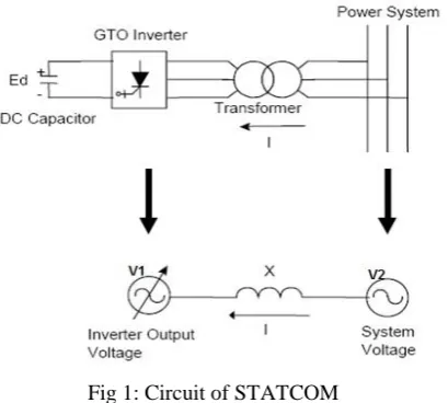
Fig 1: Circuit of STATCOM
Now we will understand how the STATCOM works though we have discussed the basic operating principle of STATCOM. As can be seen from the figure above, source V1 represents the output voltage of the STATCOM. In case of reactive power demand increases in the power system, STATCOM increases its output voltage V1 while maintain the phase difference between V1 and V2 to zero (it shall be noted here that there will always exists small phase angle between V1 and V2 to cater for the leakage impedance drop in the interconnecting Transformer ). As V1 > V2, reactive power will flow from STATCOM to the power system. Thus STATCOM, supplies reactive power and acts as reactive power generator. Again, if the voltage of power system increase due to load throw off, STATCOM will reduce its output voltage V1 and therefore will absorb reactive power to stabilize the voltage to normal value. The above mode of operation of STATCOM is called Voltage Regulation Mode. But as we know every equipment has got their own limitations, so STATCOM must also have some limitation of supplying or absorbing reactive power. Yes, there exists a limitation and this limitation is imposed by the current carrying capacity of force commutated devices like IGBT, GTO etc. Therefore, if the operation of STATCOM reaches their limitation, it does not further increases or decreases its output voltage V1 rather it supplies or absorbs fixed reactive power equal to its limiting value at a fixed voltage and current and acts like constant current source. This mode of operation of STATCOM is called VAR Control Mode. Thus the operation of STATCOM can be classified into two modes:
B. Unified Power Flow Controller (UPFC):
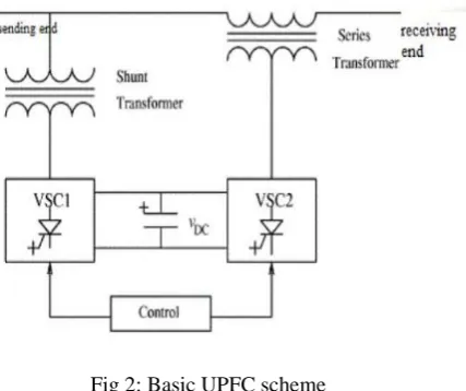
Unified Power Flow Controller (UPFC), as a representative of the third generation of FACTS devices, is by far the most comprehensive FACTS device, in power system steady-state it can implement power flow regulation, reasonably controlling line active power and reactive power, improving the transmission capacity of power system, and in power system transient state it can realize fast-acting reactive power compensation, dynamically supporting the voltage at the access point and improving system voltage stability, moreover, it can improve the damping of the system and power angle stability.UPFC consist of two back to back converters named VSC1 and VSC2, are operated from a DC link provided by a dc storage capacitor.
These arrangements operate as an ideal ac to ac converter in which the real power can freely flow either in direction between the ac terminals of the two converts and each converter can independently generate or absorb reactive power as its own ac output terminal.
Fig 2: Basic UPFC scheme
independent of the reactive power exchanged by VSC1. Obviously, there can be no reactive power flow through the UPFC dc link.
C. Static Synchronous Series Compensator (SSSC):
Static Synchronous Series Compensator (SSSC) is a modern power quality FACTS device that employs a voltage source converter connected in series to a transmission line through a transformer. The SSSC operates like a controllable series capacitor and series inductor. The primary difference is that its injected voltage is not related to the line intensity and can be managed independently. This feature allows the SSSC to work satisfactorily with high loads as well as with lower loads.
The Static Synchronous Series Compensator has three basic components: 1) Voltage Source Converter (VSC) – main component
2) Transformer – couples the SSSC to the transmission line
3) Energy Source – provides voltage across the DC capacitor and compensate for device losses
a)Operation and Capabilities:
Static synchronous series compensator works like the STATCOM, except that it is serially connected instead of shunt. It is able to transfer both active and reactive power to the system, permitting it to compensate for the resistive and reactive voltage drops – maintaining high effective X/R that is independent of the degree of series compensation. However, this is costly as a relatively large energy source is required. On the other hand, if control is limited to reactive compensation then a smaller supply should be enough. In this case only the voltage is controllable because the voltage vector forms 90º with the line intensity. Subsequently, the serial injected voltage can advance or delay the line current, meaning, the SSSC can be uniformly controlled in any value. The SSSC when operated with the proper energy supply can inject a voltage component, which is of the same magnitude but opposite in phase angle with the voltage developed across the line. As a result, the effect of the voltage drop on power transmission is offset. In addition, the static synchronous series compensator provides fast control and is inherently neutral to sub-synchronous resonance.
b)Modes of Operation:
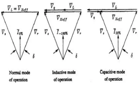
Fig 3: Modes Of Operation
It can be noted that the static synchronous series compensator does not only increase the transferable power but it can also decrease it, by simply reversing the polarity of the injected voltage. This reversed polarity voltage is fed directly to the line voltage drop as if the line impedance was increased. In short, the effects of reactance compensation on normalized power flow in the transmission line are as follows:
a) When the emulated reactance is capacitive, the active and reactive power flow increases and the effective reactance decreases as the reactance compensation increases in the positive direction.
b) When the emulated reactance is inductive, the active and reactive power flow decrease and the effective reactance increases as the reactance compensation increases in the negative direction.
III.
CONTROL
STRATEGIES
A. SOFT COMPUTING:
Soft Computing is the fusion of methodologies that were designed to model and enable solutions to real world problems, which are not modeled or too difficult to model, mathematically.
Soft computing is a consortium of methodologies that works synergistically and provides, in one form or another, flexible information processing capability for handling real-life ambiguous situations. Its aim is to exploit the tolerance for imprecision, uncertainty, approximate reasoning and partial truth in order to achieve tractability, robustness and low-cost solutions. The guiding principle is to device methods of computation that lead to an acceptable solution at low cost, by seeking for an approximate solution to an imprecisely or precisely formulated problem .
1) Artificial neural network(ANN) :
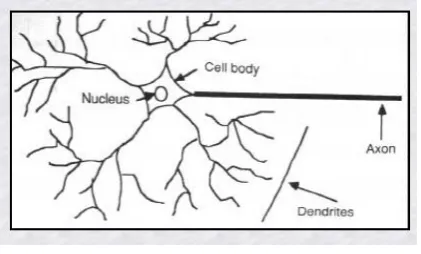
Artificial neural networks (ANN) or connectionist systems are computing systems that are inspired by, but not necessarily identical to, the biological neural networks that constitute animal brains. Such systems "learn" to perform tasks by considering examples, generally without being programmed with any task-specific rules[39]. An ANN is based on a collection of connected units or nodes called artificial neurons, which loosely model the neurons in a biological brain. Each connection, like the synapses in a biological brain, can transmit a signal from one artificial neuron to another. An artificial neuron that receives a signal can process it and then signal additional artificial neurons connected to it.In common ANN implementations, the signal at a connection between artificial neurons is a real number, and the output of each artificial neuron is computed by some non-linear function of the sum of its inputs. The connections between artificial neurons are called 'edges'. Artificial neurons and edges typically have a weight that adjusts as learning proceeds. The weight increases or decreases the strength of the signal at a connection. Artificial neurons may have a threshold such that the signal is only sent if the aggregate signal crosses that threshold. Typically, artificial neurons are aggregated into layers. Different layers may perform different kinds of transformations on their inputs. Signals travel from the first layer (the input layer), to the last layer (the output layer), possibly after traversing the layers multiple times.The original goal of the ANN approach was to solve problems in the same way that a human brain would. However, over time, attention moved to performing specific tasks, leading to deviations from biology.
Fig 5:Components Of A Neuron
2) Genetic Algorithm(GA):
fitness is usually the value of the objective function in the optimization problem being solved. The more fit individuals are stochastically selected from the current population, and each individual's genome is modified (recombined and possibly randomly mutated) to form a new generation. The new generation of candidate solutions is then used in the next iteration of the algorithm. Commonly, the algorithm terminates when either a maximum number of generations has been produced, or a satisfactory fitness level has been reached for the population. A typical genetic algorithm requires:
1. A genetic representation of the solution domain, 2. A fitness function to evaluate the solution domain.
A standard representation of each candidate solution is as an array of bits. Arrays of other types and structures can be used in essentially the same way. The main property that makes these genetic representations convenient is that their parts are easily aligned due to their fixed size, which facilitates simple crossover operations. Variable length representations may also be used, but crossover implementation is more complex in this case. Tree-like representations are explored in genetic programming and graph-form representations are explored in evolutionary programming; a mix of both linear chromosomes and trees is explored in gene expression programming. Once the genetic representation and the fitness function are defined, a GA proceeds to initialize a population of solutions and then to improve it through repetitive application of the mutation, crossover, inversion and selection operators.
a)Initialization:
The population size depends on the nature of the problem, but typically contains several hundreds or thousands of possible solutions. Often, the initial population is generated randomly, allowing the entire range of possible solutions (the search space). Occasionally, the solutions may be "seeded" in areas where optimal solutions are likely to be found. The next step is to generate a second generation population of solutions from those selected through a combination of genetic operators: crossover (also called recombination), and mutation. For each new solution to be produced, a pair of "parent" solutions is selected for breeding from the pool selected previously. By producing a "child" solution using the above methods of crossover and mutation, a new solution is created which typically shares many of the characteristics of its "parents". New parents are selected for each new child, and the process continues until a new population of solutions of appropriate size is generated. Although reproduction methods that are based on the use of two parents are more "biology inspired", some research[ suggests that more than two "parents" generate higher quality chromosomes. In addition to the main operators above, other heuristics may be employed to make the calculation faster or more robust. The speciation heuristic penalizes crossover between candidate solutions that are too similar; this encourages population diversity and helps prevent premature convergence to a less optimal solution.
b)Termination:
budget (computation time/money) reached The highest ranking solution's fitness is reaching or has reached a plateau such that successive iterations no longer produce better results.
IV.
METHOLOGY
The IEEE 14 bus system is used as the base system in which a three phase to ground fault is created at t= 0.2s in bus7. It will be cleared at t= 0.3s. In the mean time the facts devices will reduce the voltage drop depending on the nature and efficiency of that particular device. Also the controllers can increase the efficiency by reducing the voltage drop to as low as possible. In this discussion we have to are comparing and checking the effect of fault without facts devices and with the above mentioned facts devices.
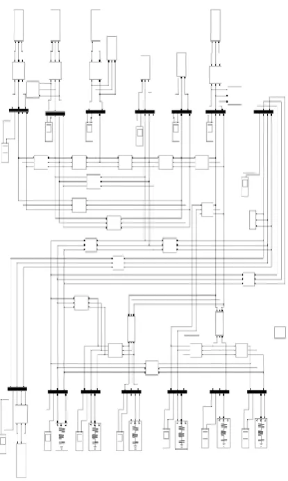
A. SIMULINK MODEL:
V.
RESULTS
A. FOR GA BASED DEVICES:
1) STATCOM:
Fig 7: The voltage waveform with THD at Bus 7 with GA based STATCOM controller
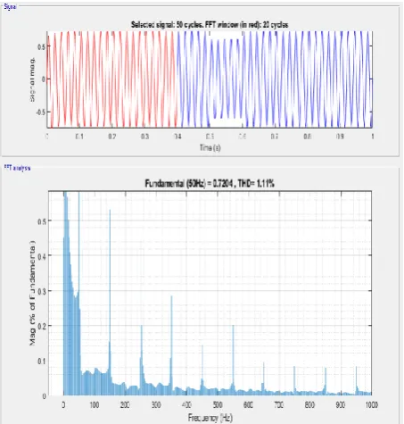
2) SSSC:
Fig 9: The voltage waveform with THD at Bus 7 with GA based SSSC controller
3) UPFC
Fig 11:The voltage waveform with THD at Bus 7 with GA based UPFC controller
B. FOR ANN BASED DEVICES:
1) STATCOM
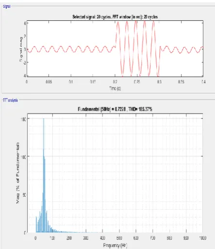
Fig 13:The voltage waveform with THD at Bus 7 with ANN based STATCOM controller
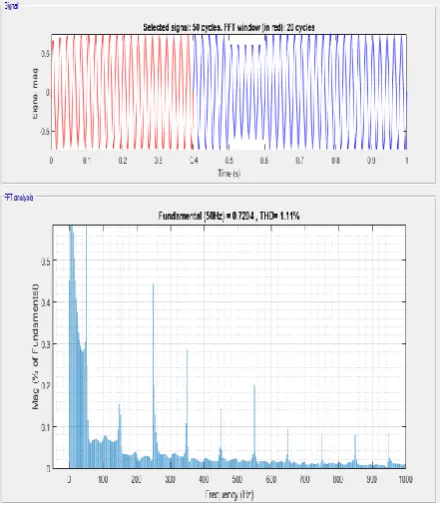
2) SSSC
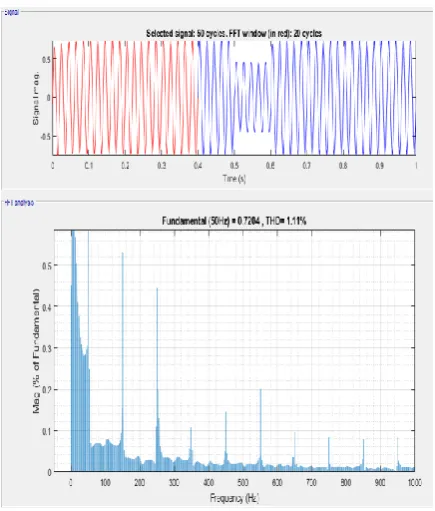
Fig 15:The voltage waveform with THD at B us 7 with ANN based SSSC controller
3) UPFC
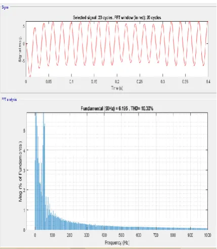
Fig 17:The voltage waveform with THD at Bus 7 with ANN based UPFC controller
VI.
CONCLUSION
From the above results we can clearly conclude the voltage recovery with UPFC is best almost 85-90%.Hence it is the most efficient device among the three devices discussed above. Also by evaluating the Total Harmonic Distortion(THD) graphs for both current and voltage for these devices the ANN has better control in reducing harmonics than GA.
DEVICE WITHOUT
FACTS
ANN
BASED
GA BASED
STATCOM - 75% 50%
SSSC - 85% 57%
UPFC - 90% 90%
Table 1:Comparision of voltage recovery with different techniques
DEVICE ANN
CONTROLLER
GA CONTROLLER
SSSC 1.11 6.52
STATCOM 12.13 22.35
UPFC 6.99 10.3
DEVICE ANN
CONTROLLER
GA CONTROLLER
SSSC 6.52 1.11
STATCOM 1.11 185.37
UPFC 4.46 9.19
Table 3: Comparasion Total Harmonic Distortion in current waveform with different techniques
REFERENCES:
[1] An introduction to neural computing / Igor Aleksander and Helen Morton
[2] R.C. Dugan, M.F. McGranaghan and H.W. Beaty, Electrical Power Systems Quality, McGraw-Hill, New York, 1996
[3] R.M. Mathur and R.K. Varma, Thyristor-Based FACTS Con- troller for Electrical Transmission Systems, IEEE Press and Wi- ley Interscience, New York, 2002
[4] Gupta S., Pachar, R., and Tiwari, H. (2010). Study on Major Issues and Their Impact on DVR System Performance
[5] El-Zonkoly A. (2006). Optimal Sizing of SSSC Controllers to Minimize Transmission Loss and a Novel Model of SSSC to Study Transient Response
[6] Y.H. Song and A.T. Johns, Eds., Flexible AC Transmission Sys- tems (FACTS), IEE Press, London, 1999. [7] N.G. Hingorani and L Gyugyi, Understanding FACTS - Concepts and Technology of Flexible AC
Transmission Systems, IEEE Press, New York, 2000
[8] N.G. Hingorani, “Flexible AC transmission”. IEEE Spectrum, v. 30, n. 4, pp. 40-44, 1993. [9] N.G. Hingorani, “Flexible AC transmission”. IEEE Spectrum, v. 30, n. 4, pp. 40-44, 1993.
[10] Neural Networks, Eric Davalo and Patrick Naim Assimov, I (1984, 1950), Robot, Ballatine, New York [11] Klimasauskas, CC. (1989). The 1989 Neuro Computing Bibliography. Hammerstrom, D. (1986). A
Connectionist/Neural Network Bibliography
[12] Learning internal representations by error propagation by Rumelhart, Hinton and Williams (1986) [13] Neural Networks by Eric Davalo and Patrick Naim
[14] Artificial Neural Networks in Medicine
http://www.emsl.pnl.gov:2080/docs/cie/techbrief/NN.techbrief.html
[16] Steady-state and dynamic models of unified power flow controller (UPFC) for power system studies a.Nabavi-Niaki
[17] & M.R.Iravani pages 1937-1343,Nov 1996
[18] https://en.wikipedia.org/wiki/Static_synchronous_compensator#cite_ref-Hingorani_Gyugyi_2017_6-0
[19] Voltage profile improvements of Mosul city ring system by STATCOM reactive power control by Dhiya A. Al-Nimma, Majed S. M. Al-Hafid, Saad Enad Mohamed Date of Conference: 8-10 Sept. 2011
[20] Network simulation with STATCON devices to avoid voltage collapse in the interconnected system M.A Choudhry,K.N Bangash,T.Mahmood Date of Conference: 18-18 Sept. 2005
[21] A state of the art STATCON for instantaneous VAr compensation and harmonic suppression to enhance powerquality S.SureshKumar,V.Subbiah,A.Kandaswaray,G.Dinesh Kumar,R.Sujay,S.Manoharan
[22] Voltage regulation by grid connected PV-STATCOM by Mohd.Azharuddin,S.R Gaigowal
[23] IEEE/CIGRE Joint Task Force on Stability Terms and Definitions, “Definition and classification of power system stability”, IEEE Transaction. On Power System Stability. Vol. 19, No. 2, pp. 1387 1400, May 2004 [24] Kakkar, V., & Agarwal, N. K “Recent trends on FACTS and D FACTS”. In modern electric power
systems (MEPS), proceedings of the international symposium IEEE. pp. 1-8, 2010.
[25] Arun Kumar and G. Priya, “Power system stability enhancement using FACTS controllers”, IEEE press, 2012.
[26] P.M Anderson , A.A Fouad “ power system control for stability enhancement”
[27] N.K.Sharma, P.P.Jagtap, “Modelling and application of Unified Power Flow Controller (UPFC)” Third International Conference on Emerging Trends in Engineering and Technology, IEEE pp 350-355, 2010 [28] Gokula Krishnan, N.Senthil Kumar, M.Abdullah Khan, “On the optimal tuning of FACTS based
stabilizers for dynamic stability enhancement in multimachine power systems”, IEEE Conference, 2011 [29] H.W. Van Der Broeck, H.C. Skudelny and G.V. Stanke, “Analysis and realization of a pulsewidth
modulator based on voltage space vectors”, IEEE Trans., Ind. Appl., v. 24, n. 1, pp. 142–150, 1988 [30] H. Akagi, “New trends in active filters for power conditioning”, IEEE Trans., Ind. Appl., v. 32, pp. 1312–
1322, 1996.
[31] K.R. Padiyar and A.M. Kulkarni, “Flexible AC transmission systems: A status review”, S¯adhan¯a, v. 22, Part 6, pp. 781–796, December 1997.
[32] N.G. Hingorani, “Introducing Custom Power”, IEEE Spectrum, v. 32, n. 6, pp. 41–48, 1995.
[33] Ghosh and G. Ledwich, Power Quality Enhancement Using Custom Power Devices , Kluwer Academic Publishers, Boston, 2002.
[34] https://en.wikipedia.org/wiki/Genetic_algorithm#CITEREFWhitley1994 [35] https://en.wikipedia.org/wiki/Artificial_neural_network