*
Corresponding author: [email protected]
Flow structures in end-view plane of slender delta wing
Besir Sahin1*, Mehmet Oguz Tasci1,Ilyas Karasu2 and Huseyin Akilli1
1
Department of Mechanical Engineering, Faculty of Engineering and Architecture, Cukurova University, 01330, Adana/ Turkey 2
Departments of Aerospace Engineering, Faculty of Aeronautics and Aerospace, Gaziantep University, 27310, Gaziantep/Turkey
Abstract. Present investigation focuses on unsteady flow structures in end-view planes at the trailing edge of delta wing, X/C=1.0, where consequences of vortex bursting and stall phenomena vary according to angles of attack over the range of 25° 35° and yaw angles, over the range of 0° 20°. Basic features of counter rotating vortices in end-view planes of delta win with 70° sweep angle, are examined both qualitatively and quantitatively using Rhodamine dye and the PIV system. In the light of present experiments it is seen that with increasing yaw angle, symmetrical flow structure is disrupted continuously. Dispersed wind-ward side leading edge vortices cover a large part of flow domain, on the other hand, lee-ward side leading edge vortices cover only a small portion of flow domain.
1 Introduction
There are several factors that influence delta wing aerodynamics, particularly formations of vortical flow over delta wing. For example, primary factors are angle of attack , yaw angle , sweep angle , roll angle, wing thickness, t leading edge geometry and conditions of free-stream as well as Reynolds Number, Re. More precisely the geometry of delta wing has close relations with the formations of leading edge vortices and their bursting incidences. Lambourne and Bryer (1961) and Sarpkaya (1971) visualized a couple of vortex bursting events over a delta wing qualitatively which were called spiral and bubble type vortex bursting as shown in Figure 1.
Fig. 1. Types of vortex bursting in a tube (Sarpkaya, 1971)
Vortex bursting phenomena is key source of striking delta wing which triggers large mechanical vibrations leading to heavy fatigue destruction and causes the loss of load-bearing ability of a material under periodic load application.
Delta wings are differed from the other type of wings because a couple of leading edge vortices, separations, vortex breakdowns and chaotic vortical flows are generally available. Representation of flow field transformations over a delta wing at a certain angle of attack, is given in Figure 2 (Anderson, 2001).
Fig. 2. Representation of flow field transformations over a delta wing under angle of attack, (Anderson, 2001)
It is identified that aerodynamics of high angle of attack, is one of the most important elements in aircraft design for the view of lift force FL. A delta wing would
also ensure high lift coefficient, CL at a larger angle of
attack, comparing to the wing of passenger aircrafts. Leading edge vortices at high angles of attack, create most portion of lift forces, FL. But, vortex bursting close
to the surface of delta wing deteriorates maneuverability of air vehicles and causes material fatigues. Comprehension of these types of flows is very important for better aircraft maneuverability. A delta wing furnishes the Unmanned Combat Air Vehicles (UCAVs) with capability of sharp maneuvers and tactical advantages. Maneuverability of all these geometrical styles are restricted by the occurrence of vortex bursting and stall influencing both overall forces and moments of aircrafts.
Ozgoren et al. (2002) reported that there are five distinct layers of vorticity in the absence of vortex breakdown at low angle of attack, . Their delta wing
model was highly swept which had =75o and they monitored flow structure at attack angles of attack of =24°, 30°, 32° and 35°. Co-existing distributions of azimuthal vorticity were classified.
Akilli et al. (2001) conducted an experimental examination to search vortex bursting sensitiveness over a delta wing at high angles of attack , via placing very thin wire orthogonally to the center of leading-edge vortex. It is shown that a thin wire could move the onset of vortex bursting by as much as fifteen vortex diameters in the upstream direction.
Cross-flow studies in end-view planes of delta wings have not been conducted in detail. There are only a few studies available. For example, Yaniktepe and Rockwell (2005) performed experimental investigations on non-slender diamond and lambda type wings to analyze flow structures at the trailing edge zones. In both wings, vortical flow structures in the cross-flow planes of trailing edge change rapidly with angles of attack, when delta wings have high sweep angle, more than 40 degree.
Although substantial scientific and technological information was obtained about instantaneous and time-averaged flow structures of delta wings with relatively large sweep angles, in recent years, but influences of yaw angle, were not studied at all. Recent demands on UCAVs have encouraged researchers to pay more attentions in characterizing flow structures of delta wings. Present investigation focuses on the unsteady flow structure which occurs downstream of onset of vortex breakdown and services as a source of buffeting and stall that reduces the lift force, FL.
Emphasizes in current investigation is given on the cross-flow in end-view planes at the trailing edge of delta wing, X/C=1.0 where consequences of vortex bursting and stall phenomena vary according to angles of attack, and yaw angle, . In the past, a great deal of effort was spent on the studies of delta wing aerodynamics with a high sweep angle . It is possible to say that flow structure over this kind of wings is understood very well. But, research work in the case of low and moderate sweep angles, of delta wing are quite limited comparing to the delta wings with high sweep angles, . On the other hand, it is worth to emphasize that the effect of yaw angles, on a delta wing aerodynamics have not been studied in detail yet. Particularly, there is no published work on the aerodynamics of slender delta wings as a function of yaw angle, . For this reason, as a motivation of present work, further studies are required in order to understand flow structures and aerodynamics of slender delta wings in detail. A low and moderate sweep angled, delta wings, which are generic plan-forms of MAVs and UCAVs, have serious control and instability problems due to not having conventional aerodynamic control surfaces. For these wings; coactions between the leading edge vortex and boundary layer, the leading edge vortex bursting, a localized surface flow separation, effects of these incidents on a wing surface vibration and buffeting are among fundamental research topics. It is possible to discover a method to control instability problems by making further investigations on these
topics and to understand flow phenomena better. Locations of vortex bursting over delta wings is not stable and displays fluctuation along the vortex axis.
Overall scene of vortex bursting close to the delta wing surface is presented in Figure 3 (Karasu et al., 2015). As seen in the figure, yaw angle, influences onset of vortex location in dramatically.
Fig. 3. Representation of symmetrical vortex bursting over a high sweep angle of delta wing, (Karasu et al., 2015)
Flow structures over the surface of non-slender diamond wing were studied by Yayla et al. (2009) using dye visualization and the Stereo Particle Image Velocimetry (PIV) System. In their study flow structures, turbulence statistics and vortex bursting transformation were examined by changing the data of yaw angle, within the range of 0° 15° for attack angle of =7° at Re=1x10⁴. They stated that when yaw angle, increases, the vortex bursting location on one side approaches to the wing apex, on the opposite side moves towards the trailing edge. Canpolat et al. (2009) monitored changes of flow structures occurred over a delta wing with respect to the angle of attack, and yaw angle, having sweep angle, of delta wing as 40°. Flow characteristics over a delta wing in plan-view plane was reported for angles of attack, =7°, 10°, 13°, and 17°, and yaw angles, =0°, 6°, 8°, and 15°. Dye visualizations of flow in cross flow planes were also reported at locations of X/C=0.6, 0.8, and 1. 0.
that wing vortex and LEX vortex are coated around each other to have combined vortex which are comparably strengthened with a new identity when yaw angle, is taken as 0°. Visualization of vorticity consecrations over a double delta wing with and without yaw angle, was also reported by Sohn et. al, 2004. Experimental work on structures of flow over surface of a non-slender delta wing with 40° sweep angle, was conducted by Canpolat et al. (2009). They stated that when a delta wing has certain value of a yaw angle , symmetrical flow structures disappear and vortex bursting goes on earlier at the windward side with respect to the leeward side. They also discovered that main vortices in cross flow planes occurred inside of vortices close to central axis of delta wing. Yayla et al. (2010) performed experimental studies on an aerodynamics of a non-slender diamond wing which has 40° sweep angle, . They pointed out that yaw angle has substantial effects on the vortex bursting using the dye visualization technique. It was concluded that up to 4° yaw angle, there are no clear changes in the vortex bursting locations, but at a higher yaw angle, after 4°, the point of vortex bursting moves towards the leading edge on the windward side, while this location moves further downstream on the leeward side. Locations of asymmetrical vortex bursting are seen over a delta wing in plain-view plane. Sohn and Chang (2010) observed the effect of central body on a yawed double delta wing using flow visualizations over a surface and wing-surface pressure measurements. They confirmed that up to 24° attack angle, availability of central body has a small effectiveness on the pressure distribution of suction side on the upper surface of wing, even at a large yaw angle of =20°.
2 Material and Method
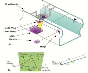
Experiments were made in a close -loop open water channel in Fluid Mechanics Laboratory at Çukurova University. Dimensions of water channel are set as 8000 mm length, 1000 mm width, 750 mm height and test section of water tunnel is made by a transparent Plexiglas which has thickness of 15 mm. The free-stream velocity is 120 mm/s which corresponds to the Reynolds number of Re=2.104 based on the cord length, C which is 120 mm. The Delta wing was kept stationary in the test section by a special mechanism. The Delta wing was hold in horizontal position by a slender support arm that stretched from mid-chord of delta wing vertically. A few dye visualization experiments were conducted in order to have an idea, for example, how flow patterns behave in end-view planes of the delta wing at a location, x/c=1.0. Fluorescent rhodamine dyes which reflect laser light were used. Rhodamine dye was conveyed in a thin slot located along the surface of delta wing. SONY HD-SR1 model video camera was employed. Schematic view of delta wing, measuring cross-section and experimental setup are shown in Fig. 4.
A 2D Particle Image Velocimetry (PIV) was used for capturing images of velocity fields. The PIV technique captures a general view of instantaneous flow data in a specified flow field. This feature lets user to examine even existence of small eddies with their effects and to provide opportunity for computing vorticity fields quantitatively. Particle Image Velocimetry (PIV) records the distance that particles move in time between two pulses of laser illuminations.
In general, the user can obtain image acquisition and data processing from the PIV system combined with the software and computer. Seeding particles moving in water flow were flashed by pulsating laser beams. A successive light sheet pulses provided the opportunity for the camera to construct an image map. Images were received by the CCD camera which has resolution of 1600×1200 pixels at a rate of 15 frames per second. Time delay between frames was taken as 170 s. To eliminate bad vectors the CLEANVEC software was used (Meinhart and Soloff (1999)) in order to remove unwanted vectors. After that to fill the places of deleted vectors bilinear interpolation with least squares fit is used. During each test, a total 1050 images were captured. The laser light sheet was set normal to the flow direction. Mirror which had 600mm-700 mm surface area located further downstream of the delta wing and was turned by 45° from the free-stream flow direction in order to deliver the vision of delta wing and cross-flow domain to the camera.
3 Result and Discussion
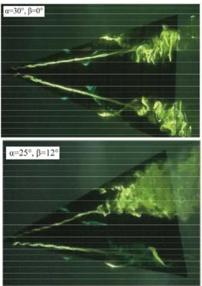
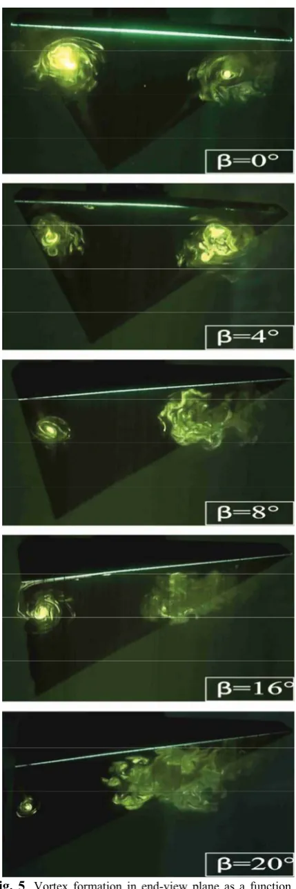
The dye visualization experiments were firstly conducted in order to study vortical flow structures further downstream of the vortex bursting at a cross-flow plane, X/C=1.0. As soon as the leading edge vortices break down, a complex flow structure is developed. A pair of main counter rotating vortices take place in end-view planes at X/C=1.0. Figs. 5, 6 and 7 demonstrate that as soon as the location of vortex breakdown comes closer to the present measuring plane, X/C=1.0 the magnitude of interactions increases violently.
A small size vorticity concentrations occurred in the counter rotating main vorticities are also well-defined. Under high angles of attach, the vortex break down occurs at an earlier stage of X/C. In this case, magnitude of large and small scales of vortices attenuated at X/C=1.0. As reported in the review work of the present study, Yaw angle, is very effective parameter in deteriorating the symmetrical flow structures leading to asymmetrical flow characteristics. Namely, on the leeward side ( Left hand side) of the delta wind, the locations of vortex break down moves further downstream while the oppositely oriented leading edge vortices breakdowns earlier. Either the leeward side or the windward side (Right hand side) leading edge vortex which ever breakdown close to end-view planes of the delta wing the magnitude of newly forming vortices become stronger. Here, free-stream flow direction is taken as a reference line for yaw angle, and locations of End-view plane or cross flow measuring plane, X/C=1 is fixed according to zero yaw angle, . A quantitative visualization of vortical flow provides detailed physics of flow structures. In order to see the effect of yaw angle, on the flow structures in end-view plane of the delta wing time-averaged velocity vectors, <V>, streamline <> and vorticity, < > are defined using instantaneous velocity data. As seen in figures, laser sheet is passed through the cross-section at
X/C=1.0 because dye visualization tests were conducted on the same cross-section.
Fig. 6. Vortex formation in end-view plane as a function of yaw angle, at angle of attack, =30°. The laser sheet is located at x/c=1.0
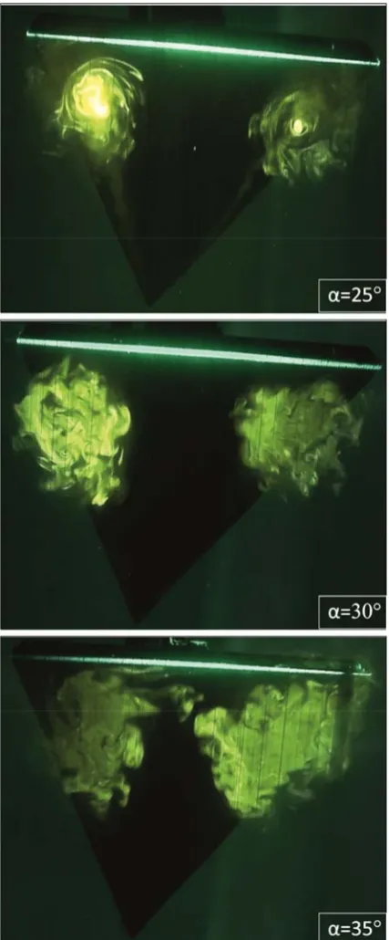
It is also reported in the review of this text, for example, taking the dimensionless cord length as X/C=1.0 and yaw angle, =0 there is a symmetrical flow structures in the observed vertical plane crossing the free-stream flow direction as seen in Fig. 8. These flow patterns are demonstrated by dye observations, animations of instantaneous flow data as well as time-averaged flow data.
Fig. 8. Vortex formation in end-view plane at angle of attack =25°, 30° and 35° and yaw angle, =0. The laser sheet is located at x/c=1.0
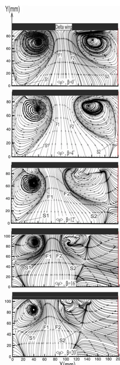
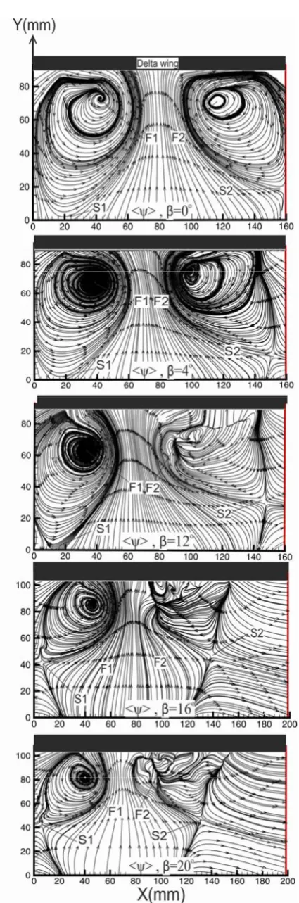
Patterns of time-averaged streamline, <>, for angles of attack of Į=25° 30° and 35°and varying yaw angles, over the range of 0° 20° are present in Figs. 9-11. The laser sheet is located at a location of x/c=1.0. Inspection of these images in figures shows that center of well-formed foci, F1 and F2, saddle points; S1 and S2
distinctly designate symmetrical flow structures and the domain of main rotating vorticity concentrations. Central points of swirl patterns of streamlines, F1 and F2
move to the left hand side of wing because of rising yaw angle, from 0° to 20°. It is observed that the swirling patterns of streamlines, <> indicating flow circulations regions are not symmetrical. Actually, saddle points S1
and S2 take place on a boundary. This borderline
identifies the border between weak flow region and free-stream flow region. Flow structures is extremely susceptible about alteration of yaw angle, and angles of attack, . Well-defined foci, F1 and F2, are presented by
contour of streamlines, <>. Below foci, F1 and F2,
two saddle points, S1 and S2 are developed.
Patterns of velocity vectors, <V> clearly show locations of swirling of flow which are coincident with the foci of streamline patterns, F1 and F2.As seen from
Fig. 9. Patterns of time-averaged streamlines, <>, with variation of yaw angle, for angle of attack, Į=25°. The laser sheet is located at x/c=1.0
Fig. 11. Patterns of time-averaged streamline, <>, with variation of yaw angle, for angle of attack Į=35°. The laser sheet is located at x/c=1.0
Fig. 13. Patterns of time-averaged distribution of velocity vectors, <V> with variation of yaw angle, for angle of attack, Į=30°.The laser sheet is located at x/c=1.0
4 Conclusion
In this work, basic features of counter rotating leading edge vortices in end-view planes of the delta wing with 70° sweep angle, were studied both qualitatively and quantitatively using Rhodamine dye and the PIV system. Experiments were conducted by altering angles of attack over the range of 25°35° and yaw angles, over the range of 0°20°for the present study. Rhodamine dye visualizations were performed in end-view planes passing through rear end of delta wing at X/C=1.0 in order to observe alterations of vortical flow structures under the effect of yaw angles, .
In end-view plane, symmetrical flow structures are developed in the case of zero yaw angles, for all case of angles of attack, . In the light of present experiments it is seen that with increasing yaw angle, symmetrical flow structure is disrupted continuously. The streamline topology <> shows that there are two saddle points, S1 and S2, and foci, F1 and F2. Saddle
points, S1 and S2, are clearly seen and located below the
foci, F1 and F2. The streamline patterns, <> show a
well-defined swirl pattern. The saddle points, S1 and S2,
and center of foci, F1 and F2, gradually move downward
and get closer to each other as angle of attack, is increased because of stall flow regions expends in size as a function of both angle of attack, and yaw angle, . Patterns of streamlines, <> of counter rotating flow recirculation are dissimilar in terms of size and magnitude. Differences between size and severity of vortices are easily seen in PIV results that are quantitatively visualized in terms of streamlines, <> and velocity vectors, <V>.
Time-averaged velocity vectors, <V> indicates a well-defined a pair of identical swirling flow cells for the case of zero yaw angle, for all cases of angles of attack, that are considered in the present work. But, a well-defined recirculating flow region on the windward side gradually attenuates and diminishes and finally a single flow circulating loop is only seen in the image of velocity vector distributions <V> on the leeward side in the case of higher yaw angle, 120. Increasing yaw angle, from =0° to =4° flow structures are subjected to small changes. Symmetrical flow structures are dramatically altered at a yaw angle of =200 compared with the case of yaw angles from = 0ͼ to =4ͼ.The distribution of time-averaged velocity vectors, <V> exhibits several small scales circulations presented by localized swirl patterns of streamlines.
Acknowledgments
This study was supported by The Scientific and Technological Research Council of Turkey (TÜBTAK) under contract number of 114M497 and Çukurova University Scientific Research Unit under contract number of FLY-2016-5845.
References
1. Akilli, H., Sahin, B., and Rockwell, D., (2001), “Control of Vortex Breakdown by a Transversely-Oriented Wire”, Physics of Fluids, 13(2):452-463
2. Anderson, J.D., (201), “Fundamentals of aerodynamics”, McGraw-Hill Higher Education, ISBN 0-07-118146-6
3. Canpolat C., Yayla S., and Sahin B., (2012), “Observation of the Vortical Flow over a Yawed Delta Wing, Journal of Aerospace Engineering”,25(4):613-626 4. Canpolat, C., Yayla, S., Sahin, B., and Akilli, H., (2009), “Dye Visualization of the Flow Structure over a Yawed Nonslender Delta Wing”, The Journal of Aircraft, 46(5), pp. 1818-1822
5. Karasu I., Sahin B., Akilli H., and Canpolat C., (2015) “Dye Visualization of a Yawed Slender Delta Wing”, Journal of Thermal Engineering, Yildiz Technical University Press, Istanbul, Turkey, 1(2-7): 646-654
6. Lambourne N. C., and Bryer D. W., (1961), “The Bursting of Leading Edge Vortices--Some Observations and Discussion of the Phenomenon”, Aeronautical Research Council Reports And Memoranda, Reports and Memoranda No. 3282
7. Meinhart and Soloff, (1999), “Cleanvec software”, Turbulence Laboratory, University of Illinois at Urbana-Champaign
7. Ozgoren, M., Sahin, B., and Rockwell, D., (2002), “Vortex Structure on a Delta Wing at High Angle-of-Attack”, AIAA Journal, 40(2):285- 292
9. Sarpkaya, T., (1971), “On stationary and travelling vortex breakdowns”, Journal of Fluid Mechanics 45(03):545-559
10. Sohn, M. H., Lee, K. Y., and Chang, J. W., (2004), “Vortex Flow Visualization of a Yawed Delta Wing with Leading-Edge Extension”, Journal of Aircraft, 41(2) 11. Sohn, M. H., and Chang J. W., (2010), “Effect of a centerbody on the vortex flow of a double-delta wing with leading edge extension”, Aerospace Science and Technology 14(1):11-18
12. Yaniktepe, B. and Rockwell D., (2005), “Flow Structure on Diamond and Lambda Planforms: Trailing-Edge Region”, AIAA Journal, 43(7), pp. 1490-1500 13. Yayla, S., Canpolat, C. Sahin, B., and Akilli, H., 82010), “Yaw angle effect on flow structure over the nonslender diamond wing”, AIAA journal, 48(10):2457-2461