Scholarship@Western
Scholarship@Western
Electronic Thesis and Dissertation Repository
6-17-2015 12:00 AM
Non-Linear Chirp Spread Spectrum Communication Systems of
Non-Linear Chirp Spread Spectrum Communication Systems of
Binary Orthogonal Keying Mode
Binary Orthogonal Keying Mode
Quan WangThe University of Western Ontario Supervisor
Jin Jiang
The University of Western Ontario
Graduate Program in Electrical and Computer Engineering
A thesis submitted in partial fulfillment of the requirements for the degree in Doctor of Philosophy
© Quan Wang 2015
Follow this and additional works at: https://ir.lib.uwo.ca/etd
Part of the Systems and Communications Commons
Recommended Citation Recommended Citation
Wang, Quan, "Non-Linear Chirp Spread Spectrum Communication Systems of Binary Orthogonal Keying Mode" (2015). Electronic Thesis and Dissertation Repository. 2898.
https://ir.lib.uwo.ca/etd/2898
This Dissertation/Thesis is brought to you for free and open access by Scholarship@Western. It has been accepted for inclusion in Electronic Thesis and Dissertation Repository by an authorized administrator of
SYSTEMS OF BINARY ORTHOGONAL KEYING MODE
by
Quan Wang
Graduate Program in Engineering Science
Department of Electrical and Computer Engineering
A thesis submitted in partial fulfillment
of the requirements for the degree of Doctor of Philosophy
The School of Graduate and Postdoctoral Studies The University of Western Ontario
London, Ontario, Canada
ii
Abstract
Chirp spread spectrum (CSS) is a suitable choice of modulation signals for wireless communications, due to its inherited advantages such as low transmission power, simplicity of implementation, good interference rejection capability. Linear chirps are common choices in practical CSS systems of binary orthogonal keying (BOK) mode. However, linear chirps generally require the time-bandwidth product of each chirp signal to be 60 sHz or more in order to achieve desirable orthogonality requirements. Thus, a BOK CSS system based on linear chirps has to occupy very wide bandwidth, which is a very precious resource for wireless communication. Clearly, the requirement on broad frequency bandwidth is a major limiting factor for the widespread adoption of the BOK linear CSS system in practice. To overcome this drawback, it is worthwhile to explore other types of chirp signals outside the linear domain, which can potentially reduce the bandwidth requirement without jeopardizing the system performance. This is the main objective of the current research. In this dissertation, a pair of non-linear chirps has been discovered, which has the potential to replace linear chirps for BOK CSS systems.
After exploring desirable properties of non-linear chirps, it is demonstrated that a significant performance advantage on orthogonality over linear chirps can be achieved by a pair of sine or cosine chirps. Subsequently, properties of sine and cosine chirps are analyzed mathematically. Derivations of spectral characteristics, autocorrelation and cross-correlation for both sine and cosine chirps are carried out respectively. Finally, comparison of sine chirps of four different time periods (i.e. half time period, full time period, triple time period, and quadruple time period) are made in terms of their cross-correlation and autocorrelation properties. It has been concluded that full period sine (FPS) chirps are the better choice for this particular application among the sine chirps.
iii
shift between linear chirps and FPS chirps has been compared. Thirdly, BER performance of the BOK FPS CSS system in a fading environment (Rayleigh channel) has been analyzed. Moreover, BER performance comparisons between linear chirps and FPS chirps in the AWGN+Rayleigh channel with and without a Doppler shift have also been studied.
Using analytic means and numerical simulations, this dissertation has conclusively demonstrated that a pair of orthogonal FPS chirps has the capability of replacing linear chirp in BOK CSS systems.
iv
Acknowledgments
Firstly, I would like to extend my sincerest gratitude to my supervisor, Professor Jin Jiang, for his continuous help, patience and guidance throughout the entire duration of my Ph.D. studies at the University of Western Ontario. Without his time, encouragement, efforts, and knowledge, this thesis would not have been completed. I could not wish for better or friendlier supervisors.
Secondly, I must express my appreciation to Dr. Xinhong Huang for her comments and suggestions in improving the quality of this thesis. Special thanks also go out to Dr. Sree Ram Valluri for helping me on the mathematical derivations in my thesis. I also would like to thank members of the Control, Instrumentation and Electrical Systems (CIES) research group at the University of Western Ontario, for their help and advice.
Of course, the greatest appreciation of all goes to my family whose insightful advice, strongest support, utmost understanding and endless patience inspired me to overcome any hurdles in my way. My beloved wife, Shugui Yang, did everything she could to support my study and never complained about my long hours work at school. Many thanks go out to my little daughter, Mandy Shiqi Wang, for her love. In addition, the love and believing from my parents played the major role in making me who I am today.
v
Table of Contents
Acknowledgments... iv
Table of Contents ... v
List of Tables ... x
List of Figures ... xi
Acronyms ... xvi
Nomenclature ... xix
1. Introduction ... 1
1.1 Chirp Spread Spectrum Systems ... 1
1.2 Previous Work ... 3
1.3 Problems, Motivations and Objectives ... 4
1.3.1 Problems ... 4
1.3.2 Motivations ... 5
1.3.3 Objectives ... 5
1.3.4 Methodology ... 6
1.3.5 Scope ... 7
1.4 Contributions of the Thesis ... 7
1.5 Organization of the Thesis ... 8
2. Chirp Spread Spectrum ... 10
vi
2.2 Pulse Compression ... 12
2.3 Principle of the BOK CSS System... 14
2.4 The BOK Linear CSS System... 17
2.5 Summary ... 23
3. Non-Linear Chirps for the BOK CSS System ... 24
3.1 Method to Explore Non-Linear Chirps for the BOK CSS System ... 24
3.1.1 General Representation for Arbitrary Chirps ... 24
3.1.2 Representation for a Pair of Chirps for the BOK CSS System ... 26
3.1.3 Method to Determine Non-Linear Chirps for the BOK CSS System ... 27
3.2 Non-Linear Chirps ... 28
3.2.1 3rd Power Function Chirps ... 28
3.2.2 Sine Chirps ... 32
3.2.3 Cosine Chirps ... 37
3.2.4 Exponential and Other Non-Linear Chirps ... 41
3.3 Conclusions ... 41
4. Properties of Sine and Cosine Chirps ... 42
4.1 Introduction ... 42
4.2 Spectral Characteristic ... 42
4.2.1 Sine Chirps ... 43
vii
4.2.3 Summary ... 46
4.3 Autocorrelation Properties ... 48
4.3.1 Sine Chirps ... 48
4.3.2 Cosine Chirps ... 52
4.3.3 Summary ... 56
4.4 Cross-correlation Properties... 56
4.4.1 Cross-correlation Coefficient ... 56
4.4.2 Orthogonal Characteristics ... 61
4.4.3 Simplification of the Cross-correlation Coefficient ... 66
4.5 Sine Chirps of Different Time Period ... 69
4.5.1 Half Period ... 70
4.5.2 Triple Period ... 73
4.5.3 Quadruple Period ... 76
4.5.4 Summary ... 79
4.6 Comparison with the Linear Counterpart ... 80
4.6.1 Spectral Characteristic ... 80
4.6.2 Autocorrelation Property ... 82
4.6.3 Cross-correlation Property ... 82
4.6.4 Summary ... 83
viii
5.1 The BOK FPS CSS System ... 85
5.2 Performance of the BOK FPS CSS System in an AWGN Channel ... 87
5.2.1 Analysis of the BOK FPS CSS System ... 87
5.2.2 Performance Comparison in the AWGN Channel ... 93
5.3 Effect of Doppler Shifts ... 94
5.3.1 Linear Chirps ... 95
5.3.2 Full Period Sine Chirp ... 98
5.3.3 Comparison of BER Performance under Different Frequency Shifts ... 109
5.4 Performance in a Rayleigh Fading Channel ... 110
5.5 Summary ... 112
6 Conclusions ... 113
6.1 Summary of Contributions ... 113
6.2 Suggestions for Future Research ... 115
References ... 116
Appendix A: Formulas Used ... 121
Appendix B: Spectrum of Sine Chirps ... 131
Appendix C: Spectrum of Cosine Chirps ... 135
Appendix D: Autocorrelation of Sine Chirps ... 139
Appendix E: Autocorrelation of Cosine Chirps ... 147
ix
Appendix G: Cross-correlation of Cosine Chirps ... 165
Appendix H: Doppler Effect on Matched Output of Sine Chirps ... 173
Appendix I: Doppler Effect on Unmatched Output of Sine Chirps ... 182
x
List of Tables
xi
List of Figures
Figure 1.1: Principle of a BOK CSS system ... 2
Figure 1.2: Principle of a DM CSS system ... 3
Figure 2.1: Principle of a matched filter ... 11
Figure 2.2: Output of a matched filter for a cosine signal ... 13
Figure 2.3: Output of a matched filter for a linear chirp signal ... 14
Figure 2.4: Model of a BOK CSS system ... 15
Figure 2.5: Linear chirps and their output waveforms ... 18
Figure 2.6: Matched and unmatched output waveforms of a linear chirp ... 20
Figure 2.7: Cross-correlation coefficient vs.
T B
c for linear chirps ... 21Figure 2.8: Eb/No vs. BER of the BOK linear CSS system in the AWGN channel ... 22
Figure 3.1: Frequency of a pair of 3rd power function chirps ... 29
Figure 3.2: Comparison of the cross-correlation coefficient vs. T Bc for linear and 3rd power function chirps ... 31
Figure 3.3: Comparison of the cross-correlation coefficient between the linear chirps and 3rd power function chirps ... 31
Figure 3.4: Frequency of sine chirps with different Ω ... 34
Figure 3.5: Comparison of the cross-correlation coefficient vs. T Bc for linear chirps and Sine chirps for four different Ω ... 34
xii
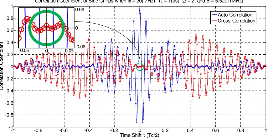
Figure 3.7: Comparison of cross-correlation coefficient of linear chirps and FPS chirps when
5.5
c
T B
=
sHz ... 36Figure 3.8: Frequency functions of cosine chirps with different Ω... 38
Figure 3.9: Cross-correlation coefficient vs.
T B
c for linear chirps and cosine chirps with different Ω ... 40Figure 3.10: Cross-correlation coefficient of linear chirps and FPC chirps when
T B
c=
5.5
sHz ... 40Figure 4.1: Bessel functions of the first kind at different orders ... 47
Figure 4.2: Discrete amplitude spectra of a sine chirp ... 47
Figure 4.3: Values of the terms in Eqn. (4.18)... 50
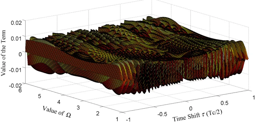
Figure 4.4: Value of the first term in Eqn. (4.18) vs. different Ω ... 50
Figure 4.5: Comparison between the all terms and the second term defined in Eqn. (4.18) when Ω =1 ... 51
Figure 4.6: Comparison between the all terms and the second term defined in Eqn. (4.18) when Ω =2 ... 51
Figure 4.7: Values of the terms in Eqn. (4.23)... 54
Figure 4.8: Value of the first term in Eqn. (4.23) vs. different Ω ... 54
Figure 4.9: Comparison between all terms and the second term defined in Eqn. (4.23) ... 55
Figure 4.10: Bessel function of the first kind of order zero ... 61
xiii
xiv
Figure 4.28: Autocorrelation & cross-correlation for QPS chirps when
B
4 4−=
17.3062
MHz... 78
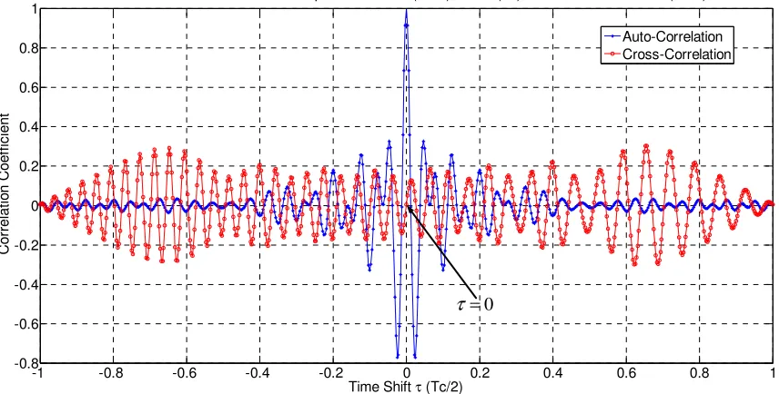
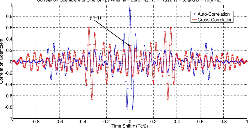
Figure 4.29: Central parts of the cross-correlation for sine chirps with different Ω ... 79
Figure 4.30: Comparison of the spectra for linear chirp and FPS chirp when
T B
c=
30
sHz . 81 Figure 4.31: Comparison of the spectra for linear chirp and FPS chirp whenT B
c=
50
sHz . 81 Figure 4.32: Autocorrelation coefficient of linear chirps vs. FPS chirps ... 82Figure 4.33: Cross-correlation coefficient of linear chirps vs. FPS chirps ... 83
Figure 5.1: A BOK FPS CSS system in the AWGN channel ... 87
Figure 5.2: Eb/No vs. BER of the BOK FPS CSS system for different
T B
c ... 92Figure 5.3: BER of the BOK FPS CSS system vs.
T B
c for different Eb/No... 92Figure 5.4: Theoretical and simulated BER for the BOK FPS CSS system ... 93
Figure 5.5: Performance of linear chirp and FPS chirp with different bandwidths in the AWGN channel ... 94
Figure 5.6: Output of the matched filter with different frequency offsets ... 97
Figure 5.7: Output of the unmatched filter in the BOK linear CSS system with different frequency offsets ... 97
Figure 5.8: Value of the first term in Eqn. (5.36) vs. different Doppler shifts and
T B
c ... 100Figure 5.9: Comparison of the matched output of the BOK FPS CSS system with no frequency offset and 78 kHz frequency offset ... 102
xv
Figure 5.11: Value of Eqn. (5.49) vs. time-frequency offset product ... 105 Figure 5.12: Comparison of the unmatched output of the BOK FPS CSS system between no frequency offset and 50 kHz frequency offset ... 107 Figure 5.13: Comparison of the unmatched output of the BOK FPS CSS system between no frequency offset and 100 kHz frequency offset ... 107 Figure 5.14: Comparison of the unmatched output of the BOK FPS between no frequency offset and 200 kHz frequency offset ... 108 Figure 5.15: Comparison of the unmatched output of the BOK FPS CSS system between no frequency offset and 300 kHz frequency offset ... 108 Figure 5.16: Eb/No vs. BER performance in the Gaussian channel for linear and FPS chirps
with different frequency shifts ... 110 Figure 5.17: Eb/No vs. BER performance for linear and FPS chirps in a Rayleigh+Gaussian
xvi
List of Theorems
Theorem 4.1 ... 48
Theorem 4.2 ... 49
Theorem 4.3 ... 52
Theorem 4.4 ... 53
Theorem 4.5 ... 56
Theorem 4.6 ... 57
Theorem 4.7 ... 58
Theorem 4.8 ... 59
Theorem 4.9 ... 66
Theorem 4.10 ... 68
Theorem 5.1 ... 98
Theorem 5.2 ... 99
Theorem 5.3 ... 101
Theorem 5.4 ... 103
Theorem 5.5 ... 104
xvii
Acronyms
AWGN Additive White Gaussian Noise BER Bit Error Rate
BOK Binary Orthogonal Keying CSS Chirp Spread Spectrum DS Direct Sequence DM Direct Modulation
DSSS Direct Sequence Spread Spectrum
Eb/No The energy per bit to noise power spectral density ratio
EMI Electromagnetic Interference FH Frequency Hopping
FSK Frequency-Shift Keying FPC Full Period Cosine FPS Full Period Sine HPS Half Period Sine
IEEE Institute of Electrical and Electronics Engineers LR-WPAN Low-rate Wireless Personal Networks
xviii
OFDM Orthogonal Frequency-Division Multiplexing PHY Physical Layer
PSK Phase-Shift Keying PN Pseudo Noise
QPS Quadruple Period Sine
QPSK Quadrature Phase-Shift Keying RTLS Real Time Location Systems SAW Surface Acoustic Wave SNR Signal-to-noise Ratio TPS Triple Period Sine UWB Ultra Wideband
xix
Nomenclature
( )
s t Signal which is sent out at the sender side
( )
y t Received signal by the receiver
( )
m
h t Impulse response of the matched filter to signal s t( )
( )
g t Output of the matched filter without Doppler shift
( )
F
ω
Spectrum of the signal s t( )( )
m
H j
ω
Transfer function of a matched filter*
( )
s t Complex conjugate of the signal s t( )
( )
c t Chirp signal
0
f Carrier frequency
B Frequency sweeping band
c
T Duration of the chirp signal in seconds
c
T B Time-bandwidth product
( )
n t An additive channel noise
Ω
Number of sweep cycles of sine or cosine chirp during the signal time period Tc
( )
τ
xx
L
r Autocorrelation coefficient of a linear chirp
S
r Autocorrelation coefficient of a sine chirp
C
r Autocorrelation coefficient of a cosine chirp
( )
C τ Cross-correlation of a signal c t
( )
L
ρ
Cross-correlation coefficient of linear chirpsS
ρ
Cross-correlation coefficient of sine chirpsC
ρ
Cross-correlation coefficient of cosine chirpsc
T B Time-bandwidth product ( )
n
J x The Bessel function of the first kind of order
n
d
f Doppler shift t
dS
f
The tolerable frequency shift for the BOK CSS system of full period sinechirp mt
dS
f
The tolerable frequency shift for the BOK CSS system of full period sinechirp to the matched output ut
dS
f
The tolerable frequency shift for the BOK CSS system of full period sine1. Introduction
1.1 Chirp Spread Spectrum Systems
Three techniques have been accepted for implementing spread spectrum modulation: frequency hopping (FH), direct sequence (DS) and chirp spread spectrum (CSS). Unlike FH and DS that employ pseudorandom coding to spread the spectrum of the information-bearing signal, CSS does not require additional coding to spread the spectrum since it can use chirp signal for coding. In addition, CSS signals exhibit a higher degree of interference rejection capability than a pure sinusoidal signal, thus making this class of signals a good candidate for use in spread-spectrum type communication systems [1]. CSS has also shown to be resistant to Doppler and other distortive effects [2, 3]. CSS-based wireless systems can transmit the signal at low transmission power by spreading the spectrum [4]. Therefore, CSS is a good choice for wireless communications, due to its innate advantages such as low transmission power, simplicity of implementation, good interference rejection capability.
adoption of CSS in various applications, such as real time location systems (RTLS) [8], industrial control [9], and sensor networking [10].
Chirp spread spectrum systems can be grouped into two categories: binary orthogonal keying (BOK) and direct modulation (DM). The BOK CSS system uses two different chirps with the same bandwidth and duration but opposite sweep polarity, e.g. linear up-chirp and linear down-up-chirp. A block diagram of a BOK CSS system is shown in Figure 1.1. There, the up-chirp and down-chirps are used to represent different data symbols. For example, bits ‘1’ and ‘0’ can be represented by chirps with positive and negative instantaneous frequency change rates, respectively. At the receiver end, corresponding matched filters are used to decode the received signal.
X
X
Figure 1.1: Principle of a BOK CSS system
Figure 1.2: Principle of a DM CSS system
The DM method has to combine with other digital modulation schemes for data transmission, while the BOK method does not. Thus, the modulation scheme of the BOK method for wireless data communication is simpler than that of the DM method. Moreover, the BOK chirp method uses two different chirps for data modulation, while the DM chirp method can just use one chirp signal for spreading. Hence, the DM method focuses on the autocorrelation of the chirp signal, which is the same as in a radar system, while the BOK method depends not only on autocorrelation characteristics but also on cross-correlation characteristics between the two chosen chirps. The BOK method is more suitable for analyzing chirps, since its performance depends more on the characteristics of chirps than the DM method does. Therefore, the BOK method is chosen in this research.
1.2 Previous Work
scheme of expanding the data throughput of a BOK CSS system by increasing the signal constellation from binary to N-ary piece linear chirps. All of these studies use linear chirps for the BOK CSS systems.
Currently, non-linear chirps have attained little acceptance for the CSS system mainly due to the following reasons: (1) limited development of nonlinear-FM generation and processing devices; (2) mathematical derivation of performance analysis for non-linear chirp signals can be cumbersome; (3) greater system complexity; (4) the linear chirp already has acceptable performance, especially for wide time-bandwidth product.
Despite these factors, many attempts have been made to explore the non-linear chirps. A method of suppressing narrowband interference in ultra wideband (UWB) systems is realized using sine chirp in [19]. Several attempts to design the exponential chirp for radar applications have been published in [20, 21]. Sinh and tan function chirps are investigated for active sonar in [22]. Atan and asinh chirps are studied in [23] to construct UWB pulses and alleviate narrowband interference (NBI). Modified sine chirps and modified tanh chirps are proposed to be used in cognitive UWB system in [24]. Range and Doppler resolutions for Gaussian and Rayleigh chirps are compared in [25]. However, none of these investigations are for the BOK CSS system. Since no non-linear chirps are proven to have potential to replace linear chirps in the BOK CSS system, as of writing this paper, very few works introduce non-linear chirps into the BOK CSS system. Multiuser chirp spread spectrum communication systems using quadratic and exponential chirps are considered in [26]. However, in this paper, the assumption of orthogonality for these chirps has not been validated.
1.3 Problems, Motivations and Objectives
1.3.1 Problems
nonlinear manner with time. Most of current works on the CSS systems are based on linear chirps [3, 27]. The performance of a BOK CSS system, such as bit error rate (BER), depends significantly on the orthogonality of the chirp signals used. The better the orthogonality of the chirp signals is, the better the BER performance of the BOK CSS system will be when other factors remain the same. Linear chirps generally require the time-bandwidth product of each chirp signal to be 60 sHz or more in order to achieve satisfactory orthogonality requirements between the chirp signals. Thus, a BOK CSS system based on linear chirps has to occupy a wide bandwidth, which is a precious communication resource. For instance, Nanotron’s CSS module nanoPAN 5360, which uses linear chirps, occupies 64 MHz bandwidth for one channel with 1µs time period for up to 2 Mbps data rate [28]. Clearly, the requirement on broad frequency bandwidth is a significant limiting factor for a linear CSS system. The question being investigated in this thesis research is to explore if there exist other forms of chirps, which provide improved orthogonality over linear chirps for the BOK CSS system.
1.3.2 Motivations
To address the above problem, it is worthwhile to explore other types of chirp signals outside the linear domain, which can potentially reduce the bandwidth requirement without jeopardizing the system performance.
1.3.3 Objectives
Based on the above motivation, the objectives of this research can be summarized as follows.
• Develop the general representations to construct arbitrary kind of chirps, and construct a pair of chirps for use in the BOK CSS systems
• Determine a pair of non-linear chirps, which can potentially be used to improve the BOK CSS system over linear chirps
• Evaluate the performance of the BOK CSS system based on the chosen non-linear chirps
1.3.4 Methodology
The following methods will be used respectively to carry out the above objectives:
• Although some non-linear chirps are presented in some literature, there is no general representation to construct a pair of non-linear chirps for the BOK CSS system. Therefore, the first task for the first objective is to find a general way to represent an arbitrary chirp, and then construct a pair of chirps to be used in the BOK CSS system. Thus, some pairs of non-linear chirps can be determined for further research.
• To be a good candidate to replace linear chirps in the BOK CSS systems, a pair of non-linear chirps should have a better orthogonal property than that of linear chirps. Thus, a comparison of cross-correlation of linear chirps and the proposed non-linear chirps can be an efficient way to determine if the non-non-linear chirps are a good candidate.
• To be a good candidate, the chosen chirp signals should have the following desirable properties: (1) They should have better orthogonal property than that of linear chirps; (2) they should have a similar autocorrelation property to linear chirps; and (3) they should lead to a reduced bandwidth requirement without jeopardizing system performance. Therefore, the properties (such as spectrum, cross-correlation, and autocorrelation) of the proposed pair of non-linear chirps need to be theoretically analyzed, so that their characteristics can be validated.
1.3.5 Scope
Since there are infinite number of non-linear chirps, it is not possible to investigate all non-linear chirps in this research. Instead, the scope of this thesis is limited to finding a pair of non-linear chirps, which can potentially be used to improve the BOK CSS system by replacing linear chirps.
1.4 Contributions of the Thesis
• One general representation is developed to construct an arbitrary kind of chirp for a given spectral bandwidth. Another general representation is generated to construct a pair of chirps for the BOK CSS system. With these two general representations, a class of non-linear chirps can be constructed and explored for the BOK CSS system.
• A method is developed to observe if a pair of candidate chirps has improved orthogonal property over their linear counterpart.
• Preliminary results have shown that significant performance advantage on orthogonality over linear chirps can be obtained using the pair of cosine or sine chirps. Thus, the properties of sine or cosine chirps are analyzed analytically. The derivations of the spectral characteristics, autocorrelation and cross-correlation for sine chirps are carried out. Similarly, the derivations of the spectral characteristics, autocorrelation and cross-correlation for cosine chirps are also carried out. A significant discovery is validated through mathematical derivation and simulation: a pair of sine or cosine chirps can become orthogonal under some conditions.
• It is found that a pair of full period sine (FPS) chirp is the better choice among the different periods of sine chirps for the BOK CSS system, in terms of the cross-correlation and autocross-correlation properties.
• The effect of a Doppler shift on the BOK FPS CSS system is derived, and then validated by simulation.
corresponding results show that a pair of orthogonal FPS chirps can achieve better BER performance than its linear counterpart in these two types of channel.
1.5 Organization of the Thesis
The organization of this dissertation is as follows:
Chapter 2 introduces the fundamental theory of the BOK CSS system, which includes: matched filter, pulse compression technique, principle of a BOK CSS system, and characteristics of linear chirps.
Chapter 3 proposed two general representations to construct arbitrary kinds of chirps, and to construct a pair of chirps for using in the BOK CSS system. In this chapter, several non-linear chirps are constructed, and their capabilities of outperforming linear chirps are explored by analyzing their cross-correlation properties. Finally, two kinds of non-linear chirps, i.e. sine and cosine chirps, have shown some interesting characteristics that are more appealing than linear chirp signals for the BOK CSS systems. This interesting finding makes sine or cosine chirps a suitable choice for chirp based signaling approach. Hence, they are chosen for further investigation in this thesis.
In Chapter 4, the properties of sine or cosine chirps are further investigated analytically. The derivations of the spectral characteristics, autocorrelation and cross-correlation for both sine chirps and cosine chirps are carried out, respectively. Finally, by comparing sine chirps with four different time periods (half time period, full time period, triple time period, and quadruple time period) in terms of the cross-correlation and autocorrelation properties, it is concluded that full period sine (FPS) chirps have greater potential for the current applications.
system is analyzed. The derivation of the effect of a Doppler shift on the FPS CSS system is carried out. The effect of Doppler shifts between linear chirp and FPS chirp is compared. Thirdly, BER performance of the BOK FPS CSS system in a fading environment (Rayleigh channel) is analyzed. Moreover, BER performance comparisons between linear chirps and FPS chirps in the AWGN+Rayleigh channel, with and without Doppler shift, are also carried out.
2. Chirp Spread Spectrum
A definition of spread spectrum that adequately reflects the characteristics of this technique is as follows [3]: “Spread spectrum is a means of transmission in which the signal occupies a bandwidth in excess of the minimum necessity to send the information; the band spread is accomplished by means of a code which is independent of the data, and a synchronized reception with the code at the receiver is used for despreading and subsequent data recovery”. Similarly, chirp spread spectrum derives its name from using modulated chirps for transmission, and the associated pulse compression techniques for encoding information. The matched filter and pulse compression concepts are fundamental to the CSS system. According to the pulse compression theory [29], the pulse compression of a chirp signal can be realized using a matched filter, which is the optimal filter in terms of achieving the maximal SNR (signal-to-noise ratio) at the filter output for performing signal detection in a white Gaussian noise environment.
2.1 Matched Filter
( )
m
h t
( )
s t
y t
( )
g t
( )
Figure 2.1: Principle of a matched filter
The criterion for the matched filter has been defined by Klauder in [31] as:
(
)
(
)
m
H j
ω
F j
∗ω
=
(2.1)where
H
m(
j
ω
)
is the transfer function of a matched filter, F( )ω
is the spectrum of the signal s t( ), which is supposed to be inputted into the matched filter, and∗
denotes the complex conjugate. From this equation, a filter is matched to the signal when its frequency response is equal to the complex conjugate of the signal spectrum. The impulse response of the matched filter to a general signal s t( ) is:( )
( )
m
h t
=
s
∗−
t
(2.2)It can be seen that
h t
m( )
is equal to the complex conjugate of the transmitted signal ( )s t after time reversion [32]. Therefore, if a signal is a real even function, i.e.
*
( )
(
)
s t
=
s
−
t
, then the impulse response of the matched filter is the transmitted signal itself, i.e.h t
m( )
=
s t
( )
.When y t( ) is processed by the matched filter, the output of the matched filter without Doppler shift, g t( ), can be expressed by the convolution integral between the filter's impulse response and the signal y t( ):
( ) ( ) m( )
g t +∞ y u h t u du
−∞
By combining Eqn. (2.2) and Eqn. (2.3), the output of the matched filter can be written as:
( ) ( ) ( ) ( , )
g t +∞ y u s u∗ t du C y s
−∞
=
∫
− = (2.4)where C y s( , ) is a cross-correlation between the received signal y t( ) and the transmitted signal s t( ). Therefore, the output of the matched filter can be calculated by performing a cross-correlation between the received signal and the transmitted signal. If the received signal is the same as or similar to the transmitted signal, i.e. y t( )=s t( ), the output of the matched filter would be the autocorrelation function of the received (or transmitted) signal [33].
In other words, output of a matched filter can be achieved by convolving the incoming signal with a conjugated and time-reversed version of the transmitted signal, or can be obtained by convolving the incoming signal with the transmitted signal if the transmitted signal is a real even function. A practical implementation of matched filtering is pulse compression because the impulse response is matched to the input pulse signals.
2.2 Pulse Compression
Pulse compression is a classical signal processing technique to increase the range resolution as well as the signal to noise ratio without having to increase the peak transmission power [34]. The critical functions in a pulse compression system are modulating the transmitted pulse in the transmitter, and the matched filtering (pulse compression) in the receiver.
The simplest transmitted pulse can be a cosine signal. The pulse is transmitted periodically, but only a single pulse is considered here as an example. Assuming the pulse starts at t=0, the signal s t( ) can be defined by the following equation, where
f
0(
0)
0cos 2 cos( ) 0
( )
0 otherwise
f t t t T
s t =
π
=ω
≤ ≤ (2.5)
A matched filter is used in the receiver to detect the incoming cosine signal. A cosine pulse to be transmitted and the corresponding output of the matched filter are shown in Figure 2.2, respectively.
Figure 2.2: Output of a matched filter for a cosine signal
Instead of a fixed frequency signal, such as a cosine signal, a short pulse can be achieved after the matched filter if the transmitted signal is implied by the wide bandwidth, which can be called spread spectrum. Linear chirp, the frequency of which increases or decreases linearly with time, is the most typically used signal in the pulse compression system. The common representation of a linear chirp can be written:
2 0
cos 2 ( ) 0
( ) 2
0 otherwise
c
L c
B
f t t t T
c t
π
T
+ ≤ ≤
=
(2.6)
where
f
0 is the carrier frequency, B is the frequency sweeping band, andT
c is the duration of the chirp in seconds. This linear chirp signal and its output after the matched filter are shown in Figure 2.3.A
m
p
lit
u
d
e
A
m
p
lit
u
d
Figure 2.3: Output of a matched filter for a linear chirp signal
By comparing the outputs after the matched filter in Figure 2.2 and Figure 2.3 respectively, a narrow pulse is achieved for the linear chirp signal but not for the cosine signal. Therefore, the energy of the linear chirp signal is compressed into a short pulse by the matched filter, is from which the term, pulse compression, is derived. Since the energy of the signal can be perserved during pulse compression [35], the short pulse will have a large increase in magnitude as shown in Figure 2.3.
Pulse compression technique associated with a chirp signal has the capability of accumulating the energy of this signal into a short pulse with an amplification in magnitude [36]. Therefore, it is more likely to be detected by the corresponding receiver when operating at low power in order to avoid use of high peak power signals. Moreover, the transmission of chirps and the use of the associated pulse compression technique make the system highly robust against interference and multipath distortions [3]. Since the chirp spread spectrum system (CSS system) is based on chirps and pulse compression technique, it inherits these advantages.
2.3 Principle of the BOK CSS System
The pulse compression technique is used in the CSS system for decoding information. A signal model of the BOK CSS system is depicted in Figure 2.4.
A
m
p
lit
u
d
e
A
m
p
lit
u
d
X
D
ec
is
io
n
D
evi
ce
1( )
c t
1( )
h t
2( )
c t
( )
s t
2( )
h t
( )
y t
1( )
g t
2( )
g t
( )
n t
X
Figure 2.4: Model of a BOK CSS system
At the transmitter side, a switching circuit is trigged by a bit stream. If a bit "1" is to be sent, the switch will be connected to the #1 chirp generator and chirp signal
c t
1( )
will be transmitted. If a bit "0" is to be sent, the switch will be connected to the #2 chirp generator and chirp signalc t
2( )
will be transmitted. Thus, the transmitted signal s t( ) is eitherc t
1( )
orc t
2( )
within a symbol period. y t( ) is the received signal at the receiver end. This signal becomes the input to both matched filters. The received signal y t( ) may be corrupted by an additive channel noise, n t( ). In this research, the effect of n t( ) is not explicitly considered to simplify the analysis of the BOK CSS system, and will be considered in Section 5. Outputs of the filters can be expressed by the convolution integral between the impulse response of the filter and the received signal:1 1
2 2
( ) ( ) ( )
( ) ( ) ( )
g t y u h t u du
g t y u h t u du
+∞ −∞
+∞ −∞
= −
= −
∫
∫
(2.7)where
h t
1( )
is the matched filter to the #1 chirp signal andh t
2( )
is the matched filter to the #2 chirp signal. Thus, according to Eqn. (2.2), these two matched filters can be represented as:1 1
2 2
( ) ( )
( ) ( )
h t c t
h t c t
∗
∗
= −
= −
By combining Eqn. (2.7) and Eqn. (2.8), the outputs of the matched filters can be written as:
1 1 1
2 2 2
( ) ( ) ( ) ( , )
( ) ( ) ( ) ( , )
g t y u c u t du C y c
g t y u c u t du C y c
+∞ ∗
−∞ +∞
∗ −∞
= − =
= − =
∫
∫
(2.9)where
C y c
( , )
1 is a cross-correlation between the received signal y t( ) and the transmitted chirp signalc t
1( )
, whileC y c
( ,
2)
is a cross-correlation between the received signal y t( ) and the transmitted chirp signalc t
2( )
. Whenc t
1( )
is transmitted, the received signal y t( ) will be the #1 chirp signal, i.e.y t
( )
=
c t
1( )
. In this case, the filter1
( )
h t
is the corresponding matched filter, while the filterh t
2( )
does not match to the received signal. The outputs of the filters as defined in Eqn. (2.9) become:1
1 1 1
2 1 2 2
( ) ( , ) ( ) ( ) ( , ) ( )
m
u
g t C c c g t
g t C c c g t
= =
= =
(2.10)
where
1 ( ) m
g t represents the output of filter
h t
1( )
which is a matched output, while2( ) u g t
is the output of filter
h t
2( )
which is an unmatched output. From Eqn. (2.10), the matched output is the autocorrelation of the #1 chirp signalc t
1( )
; while the unmatched output is the cross-correlation betweenc t
1( )
andc t
2( )
. The output of the corresponding matched filter can be represented as the autocorrelation function of the received (or transmitted) chirp signal, while the output of the corresponding unmatched filter can be represented as the cross-correlation function between the two chirp signals.Given a signal c t( ), its autocorrelation function R( )
τ
can be defined as [37]:*
( ) ( ) ( ) ( ) ( )
R τ cτ c∗ τ ∞ c t c t τ dt
−∞
= ∗ − =
∫
− (2.11)( ) ( ) ( )
( )
( ) ( )
c t c t dt
R r
E c E c
τ
τ
τ
∞ ∗
−∞ −
= =
∫
(2.12)where E c( ) ∞c t dt2( )
−∞
=
∫
is the energy of the signalc t
( )
[12].Similarly, for any two signals,
c t
1( )
andc t
2( )
, the cross-correlation C( )τ
with time shiftτ
can be defined in [37] by Eqn. (2.13).1 2 1 2
( ) ( ) ( ) ( ) ( )
C τ c τ c ∗ τ ∞ c t τ c ∗ t dt
−∞
= ∗ − =
∫
+ (2.13)Further, the cross-correlation coefficient between
c t
1( )
andc t
2( )
can be representedin Eqn. (2.14).
1 2
11 22 11 22
( ) ( ) ( )
( )
(0) (0) (0) (0)
c t c t dt
C
R R R R
τ
τ
ρ τ
∞
∗
−∞ +
= =
× ×
∫
(2.14) where R11(0) and
R
22(0)
are the autocorrelation of the signalc t
1( )
andc t
2( )
respectively. The cross-correlation indicates the degree of linear association or correlation between two signals.
2.4 The BOK Linear CSS System
Linear up-chirp and down-chirp are common choices in a practical BOK CSS system since they are the least complex. In complex baseband form, one common way of representing a linearly swept chirp signal is given in [18]:
[
]
[
]
2
1 0 0
2
2 0 0
Up : cos 2 ( ) cos (2 )
2 2 2
Down : cos 2 ( ) cos (2 )
2 2 2
c c
L
c c
L
T T
t
c f t f t t t t
T T
t
c f t f t t t t
π
µ
π
πµ
π
µ
π
πµ
= + = + − ≤ ≤
= − = − − ≤ ≤
(2.15)
common bandwidth B . Since almost all existing literature about linear chirps uses
2
2
c c
T
t
T
−
≤ ≤
for the time period, the time period for all chirp signals in this thesis is set as−
T
c2
≤ ≤
t
T
c2
in order to remain consistent.The linear up-chirp signal increases its instantaneous frequency with time. Inversely, the linear down-chirp signal decreases its instantaneous frequency with time. The time-frequency characteristics of a linear up-chirp and down-chirp, along with their corresponding real parts are depicted in Figure 2.5.
2 0 0 4 0 0 6 0 0 8 0 0 1 0 0 0 1 2 0 0 1 4 0 0 1 6 0 0
- 1
- 0 . 8 - 0 . 6 - 0 . 4 - 0 . 2
0
0 . 2
0 . 4
0 . 6
0 . 8
1
2 0 0 4 0 0 60 0 8 0 0 1 0 0 0 1 2 0 0 1 4 0 0 1 6 0 0
- 1
- 0 . 8 - 0 . 6 - 0 . 4 - 0 . 2
0
0 . 2
0 . 4
0 . 6
0 . 8
1
c
B T
µ=
c
B T
µ= −
2 c
T
− 2
c
T
0
f
0 t
t f
f
/ 2
B
/ 2
B
/ 2
B
−
/ 2
B
−
0
f
0 2
c
T
− 2
c
T
c
T
Figure 2.5: Linear chirps and their output waveforms
2
1 0
2
2 0
Up Matched Filter: ( ) cos 2 ( )
2 2 2
Down Matched Filter: ( ) cos 2 ( )
2 2 2
c c
L
c c
L
T T
t
h t b f t t
T T
t
h t b f t t
π
µ
π
µ
= − − ≤ ≤
= + − ≤ ≤
(2.16)
where b is a scaling factor for gain. In most applications of linear chirp, b is set as
4
µ
so that the gain of the matched filter at frequencyf
0 is a unit [38]. If the matched filter is centered at time t , an analytical expression for the output waveform of the matched filter (g t
Lm( )
) can be achieved by combining Eqn. (2.15) and Eqn. (2.16) into Eqn. (2.3) as given by [2]:0
sin ( )
( ) cos(2 )
2 2 2
c
m c c
L
t T t T T
g t f t t
t
πµ
µ
π
πµ
−
= − ≤ ≤ (2.17)
The signal produced at the unmatched filter is also given in [18]:
(
)
2(
)
20
cos(2 ) ( )
2 2
u
L c c
c
f t
g t C T B t jS T B t
T B
π π π
µ µ
= − + −
(2.18)
where C x( ) and S x( ) are both Fresnel functions [39].
can then decide which signal (
c
L1 orc
L2) is transmitting. The bigger this difference is, the more precise the achieved decision will be.1 0 0 2 0 0 3 0 0 4 0 0 5 0 0 6 0 0 7 0 0 8 0 0 - 0 . 8
- 0 . 6 - 0 . 4 - 0 . 2
0
0 . 2 0 . 4 0 . 6 0 . 8
1
Matched Output UnMatched Output
A= T Bc
(Tc / 2)
τ
Figure 2.6: Matched and unmatched output waveforms of a linear chirp
In digital communication theory, the most frequently assumed model for a transmission channel is the additive white Gaussian noise (AWGN) channel. Bit error rate for the BOK linear CSS system in the AWGN channel (
P
bL) can be calculated by [18]:(
)
( ) ( )2 2
2
1 0
1
, ( )
2
L L
a b
L
b L L L L
P Q a b I a b e
+
−
= − (2.19)
2 0
0
2 0
0
(1 1 ( ) )
2
(1 1 ( ) )
2
b L
L
b L
L
E J
a
N
E J
b
N
ρ
ρ
− −
=
+ −
=
(2.20)
where Eb N0 is the energy per bit to noise power spectral density ratio [41].
ρ
L is a cross-correlation coefficient of the linear chirps, which can be obtained by substituting Eqn. (2.15) into Eqn. (2.14). The derivation process is presented in [18], and the result is given by Eqn. (2.21).2 2
2 2
0 0
1
( cos ) ( sin )
2 2
c c
T B T B
L
c
v v
dv dv
T B
π
π
ρ
=∫
+∫
(2.21)From Eqn. (2.21), it can be observed that
ρ
L depends on the time-bandwidth product (T B
c ). The relationship betweenT B
c andρ
L is graphically shown in Figure 2.7.Figure 2.7: Cross-correlation coefficient vs.
T B
c for linear chirpsAs shown, the magnitude of
ρ
L decreases rapidly asT B
c increases from zero to 20 sHz. However, the magnitude ofρ
L changes slightly during the period in whichT B
c is0 10 20 30 40 50 60 70 80 90 100
0 0.1 0.2 0.3 0.4 0.5 0.6 0.7 0.8 0.9 1
Time-Bandwith Product (sHz)
M
a
g
n
it
u
d
e
o
f
C
ro
s
s
-C
o
rr
e
la
ti
o
n
C
o
e
ff
ic
ie
n
t
(
ρL
from 20 sHz to 100 sHz. If
T B
c goes beyond 60 sHz, the magnitude ofρ
L will be less than 0.05. Even whenT B
c is 100 sHz, these two chirps cannot be considered asorthogonal although
ρ
L is close to zero. Therefore, the linear chirps can only be considered as quasi-orthogonal [16].The relationship between
ρ
L and the BER performance of the BOK linear CSS system in the AWGN channel is depicted in Figure 2.8 [18]. It can be observed from Figure 2.8 that the value ofρ
L has significant effects on the BER performance of the BOK CSS system. The smaller the value ofρ
L is, the better BER performance will be. Whenρ
L is perfectly equal to zero, which means the two chirps are orthogonal with each other, the best BER performance for the BOK CSS system will be achieved. Generally, the time-bandwidth product (T B
c ) of the BOK linear CSS system needs to be set as 60 sHz or higher for satisfactory orthogonality. As a result, the BOK linear CSS system has to occupy wide frequency bandwidth (B) when the chirp duration (T
c) is short such as 1 µs. Since the data rate is inversely proportional to the chirp duration, the shorter the chirp duration is, the higher data rate will be. For instance, the chirp duration in Nanotron’s CSS system [28] is 1µs for up to 2 Mbps data rate.Figure 2.8: Eb/No vs. BER of the BOK linear CSS system in the AWGN channel
-5 0 5 10 15
10-8 10-6 10-4 10-2 100
BER Performance of the BOK Linear CSS in the Gaussian Channel
Eb / N0 (dB)
B
it
E
rr
o
r
R
a
te
(
B
E
R
)
ρL = 0
ρL = 0.2
ρL = 0.4
ρL = 0.6
2.5 Summary
3. Non-Linear Chirps for the BOK CSS
System
The linear chirps are the most commonly used signals in the CSS BOK system, but they have some drawbacks for the BOK mode as described in Section 2.4. A pair of non-linear chirps may be a better choice if they can outperform their non-linear counterpart. Therefore, this section explores some non-linear chirps in two steps. Firstly, a method is presented to briefly analyze a pair of non-linear chirps against linear chirps for the BOK CSS system. Secondly, with this method, some non-linear chirps (such as 3rd power function chirps, sine chirps, cosine chirps, and exponential chirps) are explored respectively to determine if they have potential to replace linear chirps in the BOK CSS system.
3.1 Method to Explore Non-Linear Chirps for the BOK
CSS System
Although representations for linear chirps and some non-linear chirps already exist, there is no general representation to construct an arbitrary chirp waveform. Moreover, most existing non-linear chirps are considered for a radar application or the DM mode in the CSS data communication systems, in which only one chirp is required. However, at least one pair of chirps is needed for the BOK mode in the BOK CSS system. Thus, there is also no general representation to construct a pair of chirps for the BOK CSS system. Therefore, a representation of a pair of non-linear chirps for the BOK CSS system also needs to be determined before the chirps are analyzed.
3.1.1 General Representation for Arbitrary Chirps
(1) Determine the type of chirp signal (e.g. linear, cosine, Gaussian, etc.) to be constructed. The type can be represented by the chirp rate function
ψ
( )t . For example, whenψ
( )t =t, which is a linear function, a linear chirp signal is going to be constructed.(2) Calculate integral of
ψ
( )t :0
( )t t
ψ
( )t dtΘ =
∫
(3.1)(3) The proposed representation needs to use a parameter
ξ
defined as follows:[
]
[
]
(
)
max ( )t min ( )t t Tc 2,Tc 2
ξ
=ψ
−ψ
∈ − (3.2)where, max
[
ψ
( )t]
means the maximum value of the functionψ
( )t for t∈ −(
Tc 2,Tc 2)
, while min[
ψ
( )t]
is the minimum value of the functionψ
( )t for the same time period.(4) Finally, this type of the chirp waveform (c t( )) can be represented using Eqn. (3.3):
( )
cos 0 2 ( ) cos 2 0 ( )B B
c t a ω t π t a π f t t
ξ ξ
= + Θ = + Θ
(3.3)
where
a
is the envelope of the chirp signal, which usually uses the rectangle pulse. Ifa
is chosen as a rectangle pulse with a value of 1, the representation of c t
( )
can be simplified as:( )
cos 0 2 ( ) cos 2 0 ( )B B
c t ω t π t π f t t
ξ ξ
= + Θ = + Θ
(3.4)
2
0 0
1
( ) ( )
2
t t
L t
ψ
t dt ktdt kt qΘ =
∫
=∫
= + (3.5)wherein, q is a constant which can be set to 0. Therefore, Eqn. (3.5) can be simplified as:
2
1 ( )
2
L t kt
Θ = (3.6)
Similarly, the parameter
ξ
for linear chirp can be given by Eqn. (3.2):(
)
when
2,
2
2
2
c c
L c c c
T
T
k
k
kT
t
T
T
ξ
=
−
−
=
∈ −
(3.7)Combining Eqn. (3.6) and Eqn. (3.7) into Eqn. (3.4), the representation for a linear chirp signal can be obtained as:
( )
0 0 20
cos 2 ( ) cos 2
2
cos 2
2
L L
L c
c
B B t
c t f t t f t k
kT
B
f t t
T
π
π
ξ
π
= + Θ = + ×
= +
(3.8)
Eqn. (3.8) is the exact same as the representation for the linear up-chirp as defined in Eqn. (2.15).
3.1.2 Representation for a Pair of Chirps for the BOK CSS
System
( )
( )
1 0 0
2 0 0
cos 2 ( ) cos 2 ( )
2 2
cos 2 ( ) cos 2 ( )
2 2
c c
c c
T T
B B
c t a t t a f t t t
T T
B B
c t a t t a f t t t
ω
π
π
ξ
ξ
ω
π
π
ξ
ξ
= + Θ = + Θ − ≤ ≤
= − Θ = − Θ − ≤ ≤
(3.9)
In order to ensure that the two chirps have the same bandwidth but opposite sweep polarity, the chirp rate function ψ( )t =d
[
Θ( )t]
dt should be confined to either of the following cases.(1) The chirp rate function
ψ
( )t is an odd function, which meansψ
( )− = −tψ
( )t for(
c 2, c 2)
t∈ −T T .
(2) The chirp rate function
ψ
( )t is an even function, which meansψ
( )− =tψ
( )t for(
c 2, c 2)
t∈ −T T ; however, its value for t∈ −
(
Tc 2,Tc 2)
contains positive and negative periods, and is symmetrically around the frequency axis. Otherwise, the frequency band occupied by the two signals defined in Eqn. (3.8) will not be the same, and, thus, will reduce the usage efficiency of the frequency spread.3.1.3 Method to Determine Non-Linear Chirps for the BOK CSS
System
As stated at the end of Section 2.4, BER performance of a BOK CSS system depends heavily on the cross-correlation coefficient of the used chirps. The smaller the value of the cross-correlation coefficient is, the better BER performance will be. Therefore, to be a good candidate to replace linear chirps in the BOK CSS systems, a pair of non-linear chirps should possess the fundamental property: they should have better orthogonal property than that of linear chirps. Thus, the comparison of cross-correlation between linear chirps and the proposed non-linear chirps can be significant to evaluate the capability of the non-linear chirps.
pair of candidate chirps that have improved orthogonal property over its linear counterpart: (1) a graphical comparison of relationship between T Bc and value of cross-correlation coefficient for both linear chirps and the candidate chirps can be used to observe if the candidate chirps have improved orthogonal property. (2) Based on the graphical comparison, if the magnitude of the cross-correlation coefficient of the candidate chirps is smaller than that of the linear chirps for the same T Bc , the candidate chirps are deemed to have an improved orthogonal property. In this case, the candidate chirps deserve more detailed investigation. More especially, if a zero crossing point exists in the curve of the candidate chirps, the candidate chirps probably can be completely orthogonal under certain condition.
3.2 Non-Linear Chirps
With the method presented in Section 3.1, some non-linear chirps are explored to determine if they have the potential to replace linear chirps in the BOK CSS system.
3.2.1 3rd Power Function Chirps
The 3rd power function is an odd function, so it can be used as the chirp rate function to construct 3rd power function chirps for BOK system. This function can be defined in the simplest case as:
3
( )
2 2
c c
P
c
T T
t
t t
T
ψ
= − ≤ ≤ (3.10)
By substituting Eqn. (3.10) into Eqn. (3.1), the parameter Θ( )t for the 3rd power function chirp can be obtained by:
3 4
( )
4
c P
c c
T
t t
t dt q
T T
Θ = = +
∫
(3.11)4
( ) 4
c P
c
T t
t
T
Θ =
(3.12)
The parameter
ξ
for the 3rd power function chirp can be obtained using Eqn. (3.2):[
]
[
]
3 3
1
max ( ) min ( )
2 2 4
c c
P P P
c c
T T
t t
T T
ξ
=ψ
−ψ
= − − = (3.13)
Since
ψ
P( )
t
=
(
t T
c)
3 is an odd function, a pair of the 3rd power chirps for a BOK CSS can be given by combining Eqn. (3.12) and Eqn. (3.13) into Eqn. (3.9):4
1 0
4
2 0
Up: ( ) cos 2
2 2
Down: ( ) cos 2
2 2
c c
P c
c
c c
P c
c
T T
t
c t f t BT t
T
T T
t
c t f t BT t
T
π
π
= + − ≤ ≤
= − − ≤ ≤
(3.14)
The frequency spectrum of a pair of the 3rd power function chirp represented by Eqn. (3.14) is shown in Figure 3.1.
3
(
)
y
= −
x
3
y
=
x
2
/
c
T
−
0
T
c/
2
0
/
2
f
−
B
0
/
2
f
+
B
0