© 2015, IRJET.NET- All Rights Reserved
Page 1976
CRACK PROPAGATION ANALYSIS USING FEM APPROACH IN TITANIUM
AND TITANIUM ALUMINIDE
Varun. M
1, Santosh. C
2, Abhijith Kashyap
3, Santhosh. M
41
Varun. M, Student, Mechanical Engg, K. S. Institute of Technology, Karnataka, India
2
Santosh. C, Asst. Prof., Mechanical Engg, K. S. Institute of Technology, Karnataka, India
3
Abhijith Kashyap, Student, Mechanical Engg, K. S. Institute of Technology, Karnataka, India
4
Santhosh. M, Student, Mechanical Engg, K. S. Institute of Technology, Karnataka, India
Abstract -
In the present work, an analysis of crack propagation in a rectangular plate made of two different materials viz. Titanium and Titanium Aluminide using FEM approach is carried out. Titanium forms an important constituent of Landing Gear application in aircrafts. The analysis is performed on four different contours viz. circle, square, rhombus and hexagon [1]. The tensile load is applied at one side of the quarter plate under symmetrical boundary conditions which results in opening mode of crack. The crack is initiated normal to the applied tensile load at the region of stress concentration. One of the best indicators of crack propagation rate, i.e. Stress Intensity Factor (SIF) is determined using Finite Element software. It is seen that the theoretically calculated values of SIF are in good agreement with each other. It can be concluded from the work that Titanium can be replaced by Titanium Aluminide considering cost, weight and other parameters.Keywords:
SIF, crack, contour, rectangular plate.
1. INTRODUCTION
Fracture is defined as the separation of a material into two or more pieces due to the action of external force/stress. The fracture of a solid material mainly occurs due to the expansion of certain displacement discontinuity surfaces within the material. If the growth of discontinuity is normal to the surface of displacement, it is known as a normal tensile crack. Suppose the displacement
Discontinuity grows tangentially to the displacement surface, it is known as a shear crack.
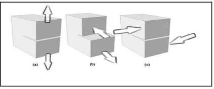
1.1 Crack Propagation Modes
There are three modes for a crack to propagate:
Mode I crack – Also called the opening mode, here the body is loaded using tensile forces. Hence, the surfaces of crack are pulled apart in the y (vertical) direction. The deformations are also symmetric with respect to the planes normal to y and z axes.
Mode II crack – Also called the sliding mode, here the solid body is loaded using shear forces which act parallel to surfaces of crack.
Fig -1: Three modes of crack propagation
This causes the 2 surfaces to slide over each other along x direction. The deformations are symmetric with respect to the plane normal to the z direction and skew symmetric with respect to the plane normal to the y axis.
skew-© 2015, IRJET.NET- All Rights Reserved
Page 1977
symmetric with respect to the plane normal to y and zaxes.
1.2 Application
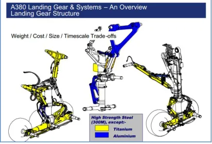
The landing gear is the structure which provides flotation on and clearance with the ground and allows it to taxi, takeoff and land. Its function is to convert uncompromised airborne into a rather awkward and clumsy ground used while braking, parking and towing the aircraft.
Fig -2: Landing Gear Structure
The landing gear system having an aircraft tricycle configuration consists of a nose landing gear and a left and right main landing gear. Each main landing gear is equipped with a brake assembly. The main landing gears are positioned in the lower left and right wing area next to mid-fuselage. The nose landing gear is retracted forward and then up into the lower fuselage. It is enclosed with the help of two doors. The main landing gear are also retracted forward and up into the left and right crack propagation analysis on Titanium and Titanium Aluminide in a part of main landing gear using FEM approach (considering only Mode-1); and then finding the Stress Intensity Factor (SIF) of both the materials [2].
2.1 Problem definition
Crack propagation analysis is carried out for a rectangular plate made of Titanium and Stress Intensity Factor is determined using Finite Element Method and Theoretical Method. The Titanium is replaced by Titanium Aluminide and Stress Intensity Factor is determined and values are compared.
Based on the result and properties of Titanium and Titanium Aluminide, the best suitable material is selected. The analysis is carried out for four different contours.
2.2 Comparison of mechanical properties of
Titanium and Titanium Aluminide
The mechanical properties of Ti and Ti-Al are compared. It is seen that Ti-Al possesses better than Ti.
Table -1: Comparison of properties of Ti and TI-Al
Property Titanium Titanium
Aluminide
Density(kg/m3) 4500 3700-3900
Young’s
Modulus(GPa) 96-125 160-176
Yield
Strength(MPa) 380-1150 400-650
Fracture
Toughness 49.8 68.2
3. CRACK PROPAGATION ANALYSIS
Standard Rectangular plate with circular hole:
© 2015, IRJET.NET- All Rights Reserved
Page 1978
Fig -3: Standard specimen3.1 FE analysis - Titanium
The Plate Dimensions are 0.2*0.4*0.005m (Quarter plate). The radius of the circular contour is 0.05m. Material is Titanium.
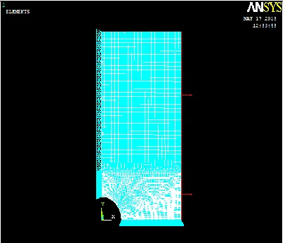
A FE model (Quarter plate due to symmetry) is created as per the above dimensions. The FEA tool used is ANSYS. Plane stress conditions are assumed since the plate thickness is very less compared to other dimensions. The Element type is Quad 8 node 82. The material properties are assigned and Map meshing is done. An external load (in terms of pressure) of 100MPa is applied along the height of the plate as shown. The other edges are displacement constrained.
Fig 4: FE model (Plate meshed and loaded)
Fig 5: Plate showing Von Mises Stress distribution
The Figure 5 shows the distribution of Von Mises stress in the rectangular plate. The critical region is found to be at the crack tip (red colour).
The above specimen is solved for STRESS INTENSITY FACTOR and the value of SIF (Mode-1) is KI = 2.4514142E+07 = 24.51 MPa√m.
In a similar manner, FEA is carried out on other types of contours viz. rhombus, hexagon and square and the SIF values are found out for Titanium metal.
3.2 FE analysis - Titanium Aluminide
A similar analysis is performed on the rectangular plate composed of Titanium Aluminide alloy.
Fig 6: FE model (Plate meshed and loaded)
© 2015, IRJET.NET- All Rights Reserved
Page 1979
Fig 7: Plate showing Von Mises Stress distributionThe Figure 7 shows distribution of Von Mises stress in the rectangular plate. The critical region is found to be at the crack tip. The above specimen is solved for Stress Intensity Factor and the value of SIF (Mode-1) is KI = 2.4514142E+07 = 24.51 MPa√m.
In a similar way, analysis is carried out on other contours viz. rhombus, hexagon and square and the values of SIF are found out for Titanium Aluminide alloy.
The Table -2 shows the Comparison of stress intensity factor (SIF) values for Ti metal and Ti – Al alloy. It can be seen from the table that the Stress Intensity Factor for both materials are same.
Table -2: Comparison of stress intensity factor (SIF) for Ti and Ti – Al
4. THEORETICAL CALCULATIONS OF STRESS
INTENSITY FACTOR
The theoretical calculations for other types of contours are done in similar way.
Table -3: Comparsion of FEM and Theoretical results
Type of
The table shows results obtained for different contours by both FEM and Theoretical methods. It can be seen that both the results are in good agreement with each other.
5. CONCLUSIONS
Since the value of Stress Intensity Factor obtained for both the materials by Finite Element Method and Theoretical method are same for mode 1 crack, considering the mechanical properties, cost ,weight and other parameters, it is concluded that Titanium aluminide is more viable than Titanium. Hence Ti can be replaced by Ti-Al in the Landing gear application.
[2] Priscilla L. Chin, Stress Analysis, Crack Propagation and Stress Intensity Factor Computation of a Ti-6Al-4V
Aerospace Bracket using ANSYS, Renssilaer
Polytechnic Institute Hartford, Connecticut, April 2011.
[3] H. M. Westergaard, On the stress distribution at the base stationary crack. Journal of Applied Mechanics, 24:109-114, 1959.
© 2015, IRJET.NET- All Rights Reserved
Page 1980
APPENDIX
SIF formula for other contours:
BIOGRAPHIES
Mr. Varun. M is currently a student in
K. S. Institute of Technology,
Bangalore, India.
Mr. Santosh. C is currently working as an Assistant Professor in K. S. Institute of Technology, Bangalore, India.
Mr. Abhijith Kashyap is currently a student in K. S. Institute of Technology, Bangalore, India.