© 2015, IRJET.NET- All Rights Reserved
Page 1812
COMPARATIVE STUDY ON RCC AND CFT MULTI-STOREYED BUILDINGS
Faizulla Z Shariff
1, Suma Devi
21
Post Graduate student, Structural Engineering, SVCE Bangalore, Karnataka, India
2Assistant Professor, Civil Engineering, SVCE Bangalore, Karnataka, India
---***---Abstract - In India reinforced concrete structures are
mostly used since this is the most convenient & economic system for low-rise buildings. However, for medium to high-rise buildings this type of structure is no longer economic because of increased dead load, less stiffness, span restriction and hazardous formwork. So the structural engineers are facing the challenge of striving for the most efficient and economical design solution. Use of composite material is of particular interest, due to its significant potential in improving the overall performance through rather modest changes in manufacturing and constructional technologies. Steel-concrete composite columns are used extensively in modern buildings. Extensive researches on composite columns in which structural steel section are encased in concrete have been carried out. In-filled composite columns, however have received limited attention compared to encased columns. In this study E-Tabs nonlinear software is used for simulation of steel concrete composite (CFT) with steel reinforced concrete structures (RCC) of G+14, G+19 and G+24 stories each are considered for comparative study. Comparison of parameters like base shear, axial force and bending moment is done.
Key Words:
Composite CFT columns, bracings, shear
wall, base shear, axial force and bending moment.
1. INTRODUCTION
In today’s modern world of creativity, two materials most certainly used as building material those are steel and concrete for structures ranging from sky scrapers to pavements, although these materials possess different characteristics and properties, they both like to complement each other in various ways. Steel has excellent resistance to tensile loading but has lesser weight ratio so slender sections are used which may be dangerous to buckling phenomenon and on the other hand concrete is good in compression. Steel may be used to influence ductility which is an important aspect for high rise building, on the other hand corrosion prevention and thermal insulation can be done by concrete. Identically
buckling of steel can also be restrained by concrete. Significantly, to bring the minimum benefits from both materials, composite construction is largely preferred. In construction of composite structures two types of columns are used they are encased column and concrete filled steel tube column.
1.1 Reinforced Concrete
Reinforced concrete consists of steel and concrete which are combined together to act as a composite material where steel helps in taking both compression and tension whereas concrete can withstand only compression. RCC is a structural material which is widely used in many kinds of structures. It is involving with steel even though economically designed and executed.
Advantages of Reinforced Concrete
1) Reinforced concrete has larger compression as compared to most other materials used for construction apart from good in tension.
2) It has greater resistance to fire than steel and ability of resisting fire for a extended period of time.
3) It has lengthy service life with very little maintenance cost.
4) It yields stiff members with least apparent deflection. 5) Yield strength of steel is nearly fifteen times the
compressive strength of structural concrete and is higher than hundred times its tensile strength.
Disadvantages of Reinforced Concrete
1) It requires necessity of mixing, casting and curing of concrete, all of which it influence the final strength of concrete. shrinkage and in the application of live loads.
1.2 Composite Column
© 2015, IRJET.NET- All Rights Reserved
Page 1813
hot rolled steel. It is generally used as a load bearingmember in a composite framed structure. Composite columns with fully and partially concrete encased steel sections concrete filled tubular section are generally used in composite construction.
Fig -1: Concrete filled tube steel section column
Fig -2: Composite encased I section Column
1.3 Concrete-filled Tube (CFT)
Concrete-filled steel tube (CFT) columns consist of a steel tube filled with concrete. The concrete core adds compressive strength and stiffness to the tubular column which reduces possible for inward local buckling. The steel tube acts as longitudinal and lateral reinforcement for the concrete core helping it to resist bending moment, shear force and twisting moment which provides confinement for the concrete. Since the benefit of these composite action of two such materials, CFT columns provide better seismic resistant structural properties such as rise in ductility, increase in strength and enormous energy absorption capacity. Round hollow sections also possess many advantages over open sections which includes architectural enhancements and an economical term in cost of materials. Due to the difficulty of connections between circular hollow sections and steel beams, their utility in structural steel work is minimum and this is because of the use of standard bolting is not feasible and not much economical so welded connections are the normal solution. The advantages of CFT column when compared to other composite materials include:
1) The steel tube provides formwork for the concrete, 2) The concrete prolongs the buckling of the steel tube
wall,
3) The excessive concrete spalling is prohibited by the tube and,
4) Composite columns extend the stiffness of a frame compared to more old steel frame construction.
While number of advantages exists, the use of Concrete filled steel tubes (CFT) in building construction has been minimum, it creates lack of construction experience, understanding of the design codes and the complexibility of connection illustrations. Perhaps, a joint is needed that could use the better strength and stiffness properties of the concrete-filled tube column yet be constructible.
1.4 Bracing
Bracing systems furnish lateral stability to the total frame work. The bracing members of similar braced frame act as a truss system to withstand lateral forces and are subjected mainly to axial stress in the elastic limit. It is easily seen that bare frames are found to be more pliable and have large section necessity to resist forces induced.Braced frames acquire their lateral forces by the bracing acts of diagonal members. The main objective of bracing system is to withstand lateral forces. Braced ones have few forces induced in the structure and at the same time produce large displacement within prescribed range. Bracing system reduces shear force and bending moment in the columns.
1.5 Shear Wall
Shear wall is a structural framework acts as a rigid vertical diaphragm efficient of conveying horizontal forces from roofs, floors and from exterior walls to the base with their planes in parallel direction. Such kinds of examples are vertical truss or reinforced-concrete wall. Horizontal forces are produced by earthquake, wind and non-uniform loads. In addition to building weight and its occupants, it creates huge twisting forces. These forces can actually tear a building apart. By placing rigid wall inside a Reinforcing frame, it maintains the shape of the model and avoids rotation at the joints. Shear walls are more important in tall buildings subjected to seismic forces and wind forces.
2. METHODOLOGY
© 2015, IRJET.NET- All Rights Reserved
Page 1814
at the base. Slabs are defined as area elements having theproperties of membrane elements and have been modelled as rigid diaphragms. Also concentric bracings and shear walls are defined as frame elements and shell area elements respectively.
3. MATERIALS AND METHODS
Table -1: Details of material properties, structural configuration and seismic data.
CFT building RCC building MATERIAL PROPERTIES
Grade of Concrete [fck] M-30 M-30 Grade of Reinforcing
Steel [fy] Fe-415 Fe-415
Grade of Structural
Steel 340N/mm2 -
Unit wt. of Concrete 25 kN/m3 25 kN/m3
SECTIONAL PROPERTIES
Column size D=800 & t=9mm D = 750mm
Beam size ISWB600 250x550
Bracing size ISMC200 200x300
Shear wall thickness 200mm 200mm
Slab thickness 150mm 150mm
BUILDING PLAN
No. of bays in
X-direction 8 8
No. of bays in
Y-direction 6 6
Width of bay in
X-direction 6m 6m
Width of bay in
Y-direction 5m 5m
Height of Storey 3m 3m
LOAD ASSIGNMENT
Live Load on roof slab 1.5kN/m2 1.5kN/m2 Live Load on floor slab 2kN/m2 2kN/m2 Weathering Course 1kN/m2 1kN/m2
Floor finishing 1kN/m2 1kN/m2
SEISMIC DATA
Seismic Zone V
Importance Factor, I 1 Response Reduction Factor, R
5 (SMRF)
Soil Type Medium Soil
Response Spectrum Function
IS 1893:2002 Spectrum
Function Damping Ratio
0.05
Time History Function Elcentro
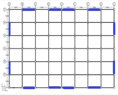
Fig -3: Plan Layout showing the location of different types of bracings and shear wall for RCC and CFT building.
4. RESULTS AND DISCUSSION
Most of the past studies on different buildings such symmetrical and unsymmetrical have adopted idealized structural systems with different bracings. Although these systems are sufficient to understand the general behaviour and dynamic characteristics, it would be interesting to know how real building will respond to earthquake forces. For this reason a hypothetical building, located on a plane ground having similar ground floor plan have been taken as structural systems for the study.The results of storey shear, axial force, bending moment and overall performance of different building models are presented and compared.
4.1 Base Shear
© 2015, IRJET.NET- All Rights Reserved
Page 1815
Chart -1: Comparison of base shear by ESA method
Chart -2: Comparison of base shear by RSA method
It can be seen from above charts, increase in storeys decreases the storey shear. Storey shear in case of bare frame is less compared to frames with bracings and shear walls, where shear walls gives maximum storey shear value in both X and Y direction. Storey shear value at base will be greater than that of top storeys. Response spectrum analysis shows lesser value of storey shear when compared with equivalent static analysis. CFT buildings show greater storey shear value when compared with RCC buildings. In case of CFT buildings, the base shear value increases upto 25% in bare frame, 7.5% with bracings and 18% with shear wall by equivalent static analysis when compared with similar features RCC buildings.
4.2 AXIAL FORCE
The resultant longitudinal component of force which acts perpendicular to the cross-section of a structural member and at its centroid producing uniform stress is termed as axial force. Axial force in columns for RCC and CFT buildings of 15 storeys are shown in figures below.
© 2015, IRJET.NET- All Rights Reserved
Page 1816
It can be seen from charts that axial force in internalcolumns is greater than external columns in case of both RCC and CFT buildings. But by comparing RCC with CFT, CFT buildings distributes load more uniformly than RCC. In case of frames with bracings and shear wall, the columns adjacent to them takes greater axial loads compared to bare frame. Overall axial force increases with introduction of different types of bracings and shear walls due to increase in dead load.
4.3 Shear Force
Force acting on a structure in a direction perpendicular to the extension of the structure is termed as shear force. Shear forces often result in shear strain. Shear force in columns for various building frame systems along longitudinal and transverse direction obtained from ETABS are shown in figures below.
Chart -4: Shear force in columns for RCC and CFT buildings (TRANSVERSE)
Chart -5: Shear force in columns for RCC and CFT buildings (LONGITUDINAL)
It can be seen from tables and figures that shear force in columns of RCC buildings has lesser values compared to CFT buildings in both longitudinal and transverse direction. In RCC buildings, bare frame value increases when compared to different types of bracings. Shear wall shows the least value of shear force in columns. While in CFT buildings, bare frame value decreases when compared to different types of bracings but shear wall shows the least value of shear force in columns in both longitudinal and transverse direction for 15 storeys.
5.
CONCLUSION
I. Base Shear:
The base shear for bare frame is less compared to bracings and shear wall in both RCC and CFT buildings.
© 2015, IRJET.NET- All Rights Reserved
Page 1817
Base shear increases in CFT buildings compared to RCC buildings.
II. Axial Force:
Axial force in internal columns is greater than external columns in case of both RCC and CFT buildings both longitudinal and transverse direction.
Shear wall shows the least value of shear force in columns.
In RCC buildings, bare frame shear force value increases when compared to RCC buildings for Time-Dependent Analysis of Composite Beams” Procedia Engineering 14 (2011) 1863– 1870
[3] Š. Gramblička and A. Lelkes “Analysis of composite steel-concrete columns” Procedia Engineering 40 ( 2012 ) 247 – 252
[4] Gianluca Ranzi, Graziano Leoni, Riccardo Zandonini “State of the art on the time-dependent behaviour of composite steel–concrete structures” Journal of Constructional Steel Research 80 (2013) 252–263
[5] Mahesh Suresh Kumawat, L.G.Kalurkar “Static & dynamic analysis of multistory building using composite structure” International Journal of Research in Engineering and Technology Volume: 03 May-2014
[6] Umesh.R.Biradar and Shivaraj Mangalgi “Seismic response of reinforced concrete structure by using different bracing systems” International Journal of Research in Engineering and Technology Volume: 03 Issue: 09 Sep-2014. [7] Kulkarni J. G., Kore P. N., Tanawade S. B. “ Seismic
Response Of Reinforced Concrete Braced Frames” International Journal of Engineering Research and
Applications (IJERA) Vol. 3, Issue 4, Jul-Aug 2013, pp.1047-1053.
[8] Nauman Mohammed, Islam Nazrul “Behaviour of Multi-storey RCC Structure with Different Type of Bracing System (A Software Approach)” International Journal of Innovative Research in Science, Engineering and Technology Vol. 2, Issue 12, December 2013.
[9] Shahzad Jamil Sardar and Umesh. N. Karadi “Effect of change in shear wall location on storey drift of multi-storey building subjected to lateral loads” International Journal of Innovative Research in Science, Engineering and Technology Vol. 2, Issue 9, September 2013.
[10] ETABS Non-linear “Extended 3-D analysis of the
building systems”, California, Computers and structures Inc., Berkeley.
[11] IS 456: 2000. “Indian Standard Code of Practice
for plain and reinforced Concrete”, Bureau of Indian Standards, New Delhi.
[12] IS 875: 1987. “Code of practice for design loads
(other than earthquake) for building and structures – Part2: Imposed loads”, Bureau of Indian Standards New Delhi.
[13] IS 1893(Part-I) 2002: Criteria for Earthquake
Resistant Design of Structures, Part-I General Provision and Buildings (Fifth Revision). Bureau of Indian Standards, New Delhi.
[14] IS 13920: 1993. “Indian Standard Code of the
practice for the detailing of Reinforced Concrete Structures Subjected to Seismic Forces” Bureau of Indian Standards, New Delhi.
[15] R.P.Johnson, “Composite structures of steel and concrete'' Volume, Blackwell Scientific publications, UK.1994.
BIOGRAPHIES
Faizulla Z Shariff PG student in Structural Engineering at SVCE, Bangalore and obtained his B.E. in Civil Engineering from Brindavan College of Engineering, Bangalore.