Volume 2010, Article ID 404927,14pages doi:10.1155/2010/404927
Research Article
Implementation and Evaluation of Multichannel
Multi-Interface Routing Mechanism with
QoS-Consideration for Ad-Hoc Networks
Shinsuke Kajioka,
1Naoki Wakamiya,
1Hiroki Satoh,
2Kazuya Monden,
2Masato Hayashi,
3Susumu Matsui,
2and Masayuki Murata
11Graduate School of Information Science and Technology, Osaka University, 1-5 Yamadaoka, Suita, Osaka 565-0871, Japan
2System Development Laboratory, Hitachi, Ltd., 292 Yoshida-cho, Totsuka-ku, Yokohama, Kanagawa 244-0817, Japan
3Automotive Business Group, Renesas Electronics Europe GmbH, Gothaer Straße 18, 40880 Ratingen, Germany
Correspondence should be addressed to Shinsuke Kajioka,[email protected]
Received 9 June 2009; Revised 31 October 2009; Accepted 21 January 2010
Academic Editor: Guillaume Chelius
Copyright © 2010 Shinsuke Kajioka et al. This is an open access article distributed under the Creative Commons Attribution License, which permits unrestricted use, distribution, and reproduction in any medium, provided the original work is properly cited.
To accommodate real-time multimedia application while satisfying application-level QoS requirements in a wireless ad-hoc network, we need QoS control mechanisms. We proposed a new routing mechanism for a wireless ad-hoc network composed of nodes equipped with multiple network interfaces. By embedding information about channel usage in control messages of OLSRv2, each node obtains a view of topology and bandwidth information of the whole network. Based on the obtained information, a source node determines a logical path with the maximum available bandwidth to satisfy application-level QoS requirements. In this paper, we evaluated feasibility of the proposal through simulation and practical experiments and confirmed that our proposal effectively transferred multimedia packets over a logical path avoiding congested links. The load on a network is well distributed and the network can accommodate more sessions than OLSRv2 and QOLSR.
1. Introduction
Wireless ad-hoc networks need no fixed communication infrastructures such as routers, switches, access points, and cables. Nodes communicate with each other through radio signals to organize a network and transmit data from one node to another. Packets are transmitted over a wireless ad-hoc network including both of best-effort traffic (file transfer, e-mail, and Web) and real-time traffic (remote monitoring, video conferencing, and VoIP). It has been recognized that the effective network capacity of a single-channel and multihop wireless network using the normal IEEE 802.11 standard MAC is not n ×(per channel throughput), but
O(n/√n)×(per channel throughput) [1], where n is the number of nodes using the same channel in the network. In [2], they further took into account phenomena, such as medium contention, channel fading, and radio interference, causing the degradation of the effective bandwidth. Since
the capacity of a wireless link is limited and the effective bandwidth is much smaller because of contention among the nodes [1,2], it is not trivial to accommodate real-time multimedia traffic in a wireless ad-hoc network. Especially, the fact that real-time applications require a certain level of QoS guarantee or control in terms of packet loss, delay, and delay jitter makes it challenging.
Over the past several years, many studies have been devoted to QoS control in wireless ad-hoc networks [3–
6]. There are several techniques or methods for controlling QoS in wireless ad-hoc networks, such as bandwidth reser-vation, channel switching, channel separation, and QoS-aware routing. At the MAC layer, some studies have been aimed to support frame transmission over a multichannel and multi-interface wireless ad-hoc network by modification of IEEE 802.11 standard MAC protocol. A node switches wireless channels [7] or both of channels and interfaces [8–
reduce the number of packet losses and improve the network throughput. In [14], they consider a multichannel, multi-interface, and multirate wireless network, but they do not consider multihop scenario. Their idea is to assign physical links having same or similar data rates on the same channel to minimize the waste of channel resources due to inconsis-tency among high and low data rate links. According to this modification, they overcome the performance degradation caused by rate adaptation. Although multiple channels and interfaces contribute to avoidance of competition and collision for a wireless channel, Kyasanur and Vaidya showed in [13] that channel switching in the same frequency band on an interface introduced nonnegligible switching delay. To tackle the problem, they proposed to classify interfaces on a node into “fixed” and “switchable” interfaces so that neighboring nodes can communicate with each other on their fixed channels to avoid the interface switching delay. In their proposal, fixed interfaces stay on their channels for a longer period than switchable interfaces.
Several works on QoS routing have been proposed for wireless ad-hoc networks. QoS-AODV [15] is a per node available bandwidth estimation protocol based on AODV. It estimates the available bandwidth from the ratio between the numbers of transmitted and received packets. The original AODV is extended by adding new fields including maximum delay extension and minimum bandwidth extension. These extension fields are included on Route Request (RREQ) and Route Reply (RREP) messages during the phase of route dis-covery. A node becomes an intermediate node on the route only if it can meet the requirements specified in the RREQ. CEDAR [16] dynamically establishes the core of the network that is given the responsibility of managing the dissemination of control messages. A node incrementally propagates the link states to the core nodes and they perform on demand route computation using the propagated link states. In the CEDAR approach, the core provides an efficient low-overhead infrastructure to perform routing, while the link state propagation mechanism ensures availability of link state information at the core nodes without incurring high over-heads. QOLSR [4,17] is a QoS-aware routing protocol based on the conventional OLSR (RFC3626). Different from QoS-AODV and CEDAR, QOLSR is a table-driven (proactive) routing protocol. QOLSR is described later in Section 4.3. All of these QoS routing protocols are less concerned about multi-interface networks; so we have to introduce routing for all channels to support multi-interface. Since any routing protocol must propagate control messages for route computation, the available bandwidth for user applications of wireless networks is decreased by the control messages.
We developed a QoS-aware routing mechanism for wire-less ad-hoc networks, especially used for temporary com-munication means such as needed at a historic landmark, a festival, or a disaster-affected area [18]. Our mechanism assumes a node equipped with multiple network interfaces and to each of which a different wireless channel can be assigned. More specifically, we consider that the number of available wireless channels is equal to or greater than the number of interfaces. Channels are assigned statically to interfaces without overlap. Our mechanism consists of
three cooperative techniques: bandwidth estimation, effi -cient message distribution, and logical routing. One interface is assigned to best-effort traffic and implements OLSRv2 (OLSR version 2) [19]. The remaining interfaces are devoted to real-time multimedia traffic. A node estimates the usage of its wireless channels and disseminates the information about the available bandwidth of the node, called the bandwidth information, to the other nodes in the whole network. For this purpose, the bandwidth information is embedded in control messages of OLSRv2 and propagated in the whole network in an efficient and effective way. In transmitting real-time packets, a source node tries to estimate the optimal path to its destination node to satisfy application-level QoS requirements knowing the topology and bandwidth information. Since the derived path, called a logical path, is different from the physical path from the source to the destination established by the underlying OLSRv2, packets are encapsulated by destination addresses of logical next-hop nodes so that it traverses the logical path. Each intermediate node receiving an encapsulated real-time packet chooses one wireless channel on the node in a stochastic manner to trans-mit the packet for efficient use of wireless channels and colli-sion avoidance. One of the key advantages of our mechanism is that it can be implemented using off-the-shelf hardware.
In the previous paper, we have described the details of our proposal and showed preliminary simulation and experimental results [18]. In this paper, we performed extensive simulation experiments to verify the feasibility of our proposal and provided details of our implemen-tation. The channel is modeled by considering a realistic propagation model and the transmission quality is assessed using the Signal-to-Interference and Noise Ratio (SINR) instead of transmission (or interference) and carrier sensing ranges, respectively, in simulation to take into account their fluctuation.
In the rest of this paper, we first briefly describe our proposal in Section 2 and explain its implementation in
Section 3. Next, we perform simulation experiments to
evaluate the effectiveness of our proposal with respect of end-to-end packet delivery ratio, delay, delay jitter, and node utilization inSection 4. Then, we further build a prototype and conduct practical experiments to verify the practicality
inSection 5. Finally, we summarize the paper and describe
some future work inSection 6.
2. QoS-Aware Routing Mechanism for
Wireless Ad-Hoc Networks
In this section, we first give an overview of our proposed mechanism and describe three key techniques in more details, that is, estimation of the available bandwidth, distribution of bandwidth information, and logical routing. We discussed more details in [18].
2.1. Overview of Our Proposed Mechanism. We consider a wireless ad-hoc network consisting of nodes equipped with
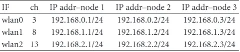
Table1: An example of wireless channel and IP address assignment.
IF ch IP addr–node 1 IP addr–node 2 IP addr–node 3 wlan0 3 192.168.0.1/24 192.168.0.2/24 192.168.0.3/24 wlan1 8 192.168.1.1/24 192.168.1.2/24 192.168.1.3/24 wlan2 13 192.168.2.1/24 192.168.2.2/24 192.168.2.3/24
generality, we number channels and interfaces from 0 toK−
1, while assigning the same number to the coupled channel and interface and numbering is the same among nodes. In our proposal, one channel numbered 0, called “best-effort channel”, is reserved for best-effort traffic and the otherK−1 channels, called “real-time channels”, are used for real-time traffic such as voice or video data. On the best-effort channel, the OLSRv2 with extension for our proposed mechanism operates for proactive IP routing and bandwidth information dissemination. We refer to IP routing as physical routing in contrast to logical routing. It is known that broadcast messages, that is, control messages of OLSRv2, may cause the hidden terminal problem because the RTS/CTS mechanism does not work when they are transmitted. So we classify channels into best-effort and real-time channels and define that no broadcast message can be transmitted on real-time channels. Because of the application scenarios, we assume that nodes are immobile. At least, the topology is stable and unchanged while a session is active. Nevertheless, condition of wireless communication can dynamically change by fading or some other environmental effects.
Table 1 shows an example of wireless channel and IP
address assignment on our proposed mechanism. In this example, each of nodes 1, 2, and 3 has three wireless network interfaces named wlan0, wlan1, and wlan2. There are three available channels without interference, 3, 8, and 13. Each interface on a node belongs to a different network, that is, 192.168.0.0/24 for wlan0, 192.168.1.0/24 for wlan1, and 192.168.2.0/24 for wlan2. Each node has a unique host address, 1, 2, and 3. By such channel and address assignment, channel switching can be easily done by changing network address of a packet at a source node and intermediate nodes. Each node always evaluates the usage of real-time channels and estimates the available bandwidth. Information about the estimated available bandwidth is disseminated over the whole network by being embedded on control messages, that is, HELLO messages and TC (Topology Control) messages of OLSRv2. In our mechanism, with a help of OLSRv2, all nodes obtain and maintain the complete information about the available bandwidth for all the nodes in the network.
Packets belonging to best-effort traffic are transmitted to a destination node on the best-effort channel. Intermediate nodes choose a next-hop node for the destination node of a received packet in accordance with the routing table main-tained by OLSRv2. On the other hand, packets belonging to real-time traffic are transmitted to a destination on real-time channels traversing a so-called logical path. A logical path consists of one or more contiguous logical links. A logical link consists of one or more physical links from one end to the other. A logical path is determined by taking into account
the topology of a wireless ad-hoc network, the available bandwidth on all physical links, and the application-level QoS requirements.
Figure 1illustrates an example of logical path
construc-tion and packet forwarding. Figure 2 shows the way that a packet is processed in our system. We refer to a flow of traffic generated by a real-time application as a session. When a packet to a new destination is generated by a real-time application, a source node determines a logical path to its destination for the session. To determine a logical path, source node S first considers a logical mesh topology on a physical network (Figure 1(b)). Each one of the logical links in the logical mesh topology is related to a physical path connecting the two ends of the logical link. Then, source node S tries to find an optimal path with respect to the application-level QoS requirements to destination node D. In this example, logical path S-B-D is chosen (Figure 1(d)) and a physical path determined by OLSRv2 could be S-E-F-D. The purpose of the logical routing is to avoid traversing a physical path containing any congested links, which deteriorate the QoS provided to an application. For packets to travel on the logical path, all packets belonging to the session for node D are encapsulated by a logical routing header, which indicates the intermediate node B and the destination node D, as shown inFigure 2. Encapsulated packets are sent to the first destination node B through the physical path from source node S to node B and then sent to the next (final) destination node D from node B (Figure 1(c)). In this case, the logical next-hop node at node S is node B while the physical next-next-hop node at node S is node A, and based on OLSRv2 physical routing. Therefore, node S sends a real-time packet to node A, then the node A forwards the packet to node B. The intermediate node A only relays a received packet to node B, which is regarded as the destination of the packet from the physical routing view point. To efficiently use the wireless bandwidth, each node chooses one real-time channel in a stochastic manner weighted by the available bandwidth among the real-time channels in forwarding a packet. If a node has two wireless network interfaces named wlan1 and wlan2, and their available bandwidths are 1 Mb/s and 2 Mb/s, respectively, then one of three real-time packets may be transmitted via wlan1 and the other two real-time packets may be transmitted via wlan2. When a packet arrives at a logical intermediate node, it is encapsulated with a new header indicating the next logical hop node (Figure 2, node B). In this way, real-time packets traverse a logical path over a network maintained by a physical routing protocol, that is, OLSRv2.
OLSR routing from S to D
Congested
A E
F S
B
D
(a) OLSR topology
A E
F S
B
D
(b) logical mesh
OLSR routing from S to B
OLSR routing from B to D A
E
F S
B
D
(c) OLSR routing
A E
F S
B
D
(d) logical routing Figure1: QoS-aware routing by proposed mechanism.
Node S Node A Node B Node D
Real-time application
Application data
Real-time application
<logical routing>
IP header (destination is B)
Logical path <logical routing> <logical routing>
B S-B-D
<channel select>
IP-based routing
<channel select>
B S-B-D D S-B-D D S-B-D
<channel select>
Physical routing on IP network Figure2: Packet processing in proposed mechanism.
Auto Rate Fallback mechanism to achieve faster transmission at higher data rates and more stable transmission at lower data rates. In such a situation, the evaluation of the available bandwidth using a data packet size and the channel’s bit-rate is not feasible, because the channel’s bit-rate may vary among next hop nodes or packets.
Instead of estimating the available bandwidth from variable values, we rather consider the radio conditions. In [20], the channel utilization ratio is calculated using radio states, that is, the time period that the channel is in a busy state during each time period. They assumed that the IEEE 802.11 wireless radio states are classified into busy state (transmitting, receiving, or carrier sensing) and idle state. In [22], Saghir et al. also derived the available bandwidth
based on the radio states. Their method computes the idle periods of the shared wireless media. In their method, each node adds up all the idle periodsTidleduring an observation interval T and then divides it by the observation interval
T to derive the idle ratioRidle. The available bandwidthB is derived by multiplying the idle ratio Ridle with the raw channel bandwidthCmax, for example, 2 Mb/s for standard IEEE 802.11 radio.
Taking these into consideration, our available bandwidth estimation method uses the idle ratioRidle, which is derived by following equation using the idle periods Tidle and the observation intervalT:
Ridle= Tidle
T . (1)
We set the observation interval to 2 s, which is the interval of HELLO message of the OLSR. To abandon the overheads introduced by the MAC protocol, we defineCmaxas the max-imum effective medium capacity. For the sake of simplicity, we assume thatCmaxis half of the raw medium capacity. The available bandwidthBk(c) of channelc(1≤c≤K−1) on
nodekis estimated by (2), whereRkidle(c) corresponds to the idle ratio of channelcon nodekandCmaxcorresponds to the maximum effective medium capacity of channelcon nodek:
Bk(c)=Rkidle(c)×Cmax. (2)
Since each node selects one interface stochastically among
K−1 real-time interfaces in transmitting a packet, we treat the total available bandwidthBkas the available bandwidth of
nodek. The total available bandwidthBkfor real-time traffic
on nodekis derived by the following equation:
Bk= K−1
c=1
Bk(c). (3)
2.3. Distribution of Bandwidth Information on OLSRv2. In order to minimize the bandwidth consumption caused by the control packets, the number of nodes forwarding TC messages is limited in the OLSRv2 (and OLSR). These forwarding nodes are called MPRs (MultiPoint Relay). Among nodes receiving TC messages or any other broadcast messages, only MPRs rebroadcast the message. MPRs are chosen in a distributed manner to keep the connectivity with the smallest number of MPRs. Nodes which select other nodes as MPR are called MPR selectors. Please refer to the standard for selection of MPR (RFC3626 1.4. or [23]).
With general OLSRv2 protocol, nodes exchange HELLO messages with their 1-hop neighboring nodes at regular HELLO intervals, for example, 2 seconds. In addition to HELLO messages, an MPR generates and disseminates TC messages at regular intervals, for example, 5 or 6 seconds. On receiving a TC message, a node builds or updates a table called Topology Set. A routing table, called Routing Set, is built and maintained when any of Link Set, Neighbor Address Association Set, 2-hop Neighbor Set, or Topology Set changes appear in the TC packet. Entries of the Routing Set are copied to the IP routing table in the system. Please refer to the Internet-Draft for more information in such as a message format [19].
In our proposal, the bandwidth information is also embedded in HELLO and TC messages by adding the extended field in the form of a TLV (Type Length Value) block. On receiving these messages, a node builds or updates the Extended Topology Set, newly introduced for the proposal, to maintain the bandwidth information.
2.4. Logical Routing Based on Bandwidth Information. On receiving a first packet to a new destination, a node generates a logical full-mesh topology for logical routing to deter-mine the maximum available bandwidth path. The current physical network topology and bandwidth information of each node are obtained from OLSRv2 with our extension. A logical link between nodeiand node jin a logical full-mesh topology is associated with the available bandwidthB(i,j). The available bandwidth B(i,j) is given as the minimum among the available bandwidth of all physical links on the widest shortest path (WSP [24]) between nodeiand node
j. When there are two or more shortest paths for a logical link, one with the minimum available bandwidth (safer side) is chosen. We should note here that the node considers the widest shortest path between logical neighboring nodeiand
j because the physical route between node i and node j
determined by OLSRv2 would be one of the minimum hop count routes. The available bandwidth of a physical link is defined as the lower one of the available bandwidth on nodes at the both edges of the physical link. For example, the available bandwidthB(S,B) inFigure 1is given asB(S,B)=
min(min(BS,BA), min(BA,BB)), whereBS,BA, andBBare the
total available bandwidth for real-time traffic on each node derived by (3).
Once a logical mesh network is constructed, a source node begins to find the optimal path with the maximum available bandwidth. First, a set of logical paths with a logical hop count of less than H are obtained from the logical mesh network. The upper boundHis introduced to avoid generating an unnecessarily long path and shorten the calculation time. Then, a source node derives the available bandwidth of each of logical paths in the set as the minimum available bandwidth of logical links constituting the logical path. Finally, the logical path with the largest available bandwidth in the set is chosen for the session. When there are two or more logical paths with the same largest available bandwidth, the logical path that has the smallest physical hop count is chosen for the session to minimize end-to-end delay. When there are two or more logical paths with the same largest available bandwidth and the smallest physical hop count, the logical path found the earliest is chosen for avoidance of overhead in memory copy.
3. Implementation of QoS-Aware
Routing Mechanism
In this section, we describe how our QoS-aware routing mechanism is implemented on a wireless ad-hoc network system. We adopt the same implementation methodology for programming simulation codes and building prototypes.
Figure 3shows module components of our proposed
mech-anism. In the figure, a node has four network interfaces and four wireless channels. We assign channel 0 for best-effort traffic and channels 1, 2, and 3 for real-time traffic.
Best-effort applications Real-time applications
UDP/IP
packet UDP/IPpacket Topology information
Topology information request
Encapsulation Decapsulation Forward LR Topology set
w BW info OLSR
Topology set Link set
TC w BW info
HELLO w BW info
NIC CH0
Available BW
Routing table
Best-effort channel
Real-time channels
BW estimator
Forward
SW
NIC CH1 NIC CH2 NIC CH3
Figure3: Module components of proposed mechanism (dashed: outgoing, plain: incoming, dot-dashed: control flow).
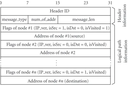
Packets generated by a real-time application are first pro-cessed by the logical routing module (LR). On receiving the first packet of a new session, the LR determines a logical path based on topology and bandwidth information maintained by the OLSR module (OLSR). Packets are encapsulated by an LR header indicating addresses of intermediate nodes of the logical path as shown in Figure 4, so that it traverses the logical path on the physical network maintained by the OLSR. Encapsulated packets are passed to the switching module (SW). The LR header consists of two parts, that is, the header information part and the logical path informa-tion part. The header informainforma-tion part consists of header identifier, message type, number of addresses in the logical path information part, and message length. The logical path information part consists of pairs of flags (IP version, source, destination, and visited bit) and an IP address, from the source node to the destination node on the logical path. The LR maintains a table of existing sessions, called the session management table, consisting of destination IP address, source port number, destination port number, timestamp, and the corresponding LR header information. Timestamp in the table is updated when the entry is made or referred to. The structure of the session management table, written in C language, is shown as follows:
struct session_management_table {
InetAddr dstAddr; /* destination IP address */ uint16_t srcPort, /* source port number */
dstPort; /* destination port number */ clocktype lastTime; /* made/referred timestamp */ void *lr_info; /* LR header information */ }
0 7 15 23 31
. . .
. . .
. . . Header ID
message type num of addr message len Flags of node #1 (IP ver, isSrc=1, isDst=0, isVisited=1)
Address of node #1(source)
Flags of node #2 (IP ver, isSrc=0, isDst=0, isVisited) Address of node #2
Flags of node #n(IP ver, isSrc=0, isDst=1, isVisited) Address of node #n(destination)
He
ad
er
infor
mat
ion
Lo
gi
cal
p
at
h
infor
mat
ion
Figure4: LR header format.
Constructed LR headers are stored in a memory, and the LR header information in the table is a pointer to the corresponding one of them prepared to avoid reconstruction overhead. If the session management table already has an entry for the session and less than 30 seconds have passed since the entry was made or referred to, the LR header is obtained from the LR header information of the entry.
Extended Topology Set localSubset
Addr BW InfomyInfo Addr BW InfoneighborInfo[ ].
. . topologySubset[ ] Addr BW InfoMPRInfo Addr BW InfoMPRselectorInfo[ ]
. . . Addr BW InfoMPRInfo Addr BW InfoMPRselectorInfo[ ].
. . . . .
Addr BW Info InetAddraddress uint32 tBW info
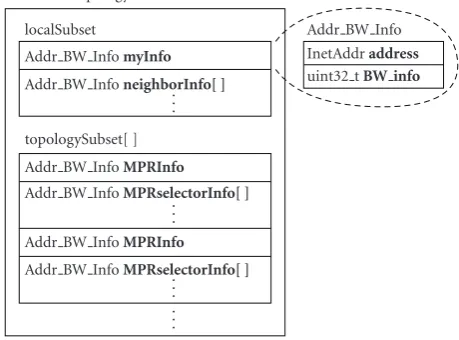
Figure5: The structure of the Extended Topology Set.
available bandwidth, which corresponds to the evaluation per interface. We assume that each interface is assigned to specific channel, respectively, and a pair of nodes can communicate on each interface each other if the nodes are connected by a bidirectional link on the best-effort channel. Finally, the SW emits the real-time packet to the physical next-hop node through the selected real-time interface. It means that the packets of a flow may be routed on different real-time interfaces at a node.
On the contrary, when the SW receives a real-time packet from a network, it searches the logical path information part in the LR header. The topmost node with unset “visited flag” is the logical next-hop node. If the logical next-hop node is not node itself, the SW sends the packet to the physical hop node on the physical path toward the logical next-hop node. Otherwise, the SW forwards the packet to its own LR. On receiving a real-time packet from the SW, the LR investigates the LR header to check whether it is the final destination or not. If the node is the final destination, the LR removes the LR header from the packet and passes it to the corresponding real-time application.
The SW is also responsible for estimation of the available bandwidth. The BW estimator module in the SW estimates the available bandwidth by (2), derives the available band-width of node by (3), and reports the result to the OLSR.
The OLSR manages a physical network by exchanging HELLO and TC messages on a best-effort channel. The OLSR obtains information about the available bandwidth of node from the SW. The obtained information is stored in the myInfofield of the localSubset in the Extended Topology Set, which deposits the original topology informa-tion of OLSRv2 and addiinforma-tionally the bandwidth informainforma-tion
(Figure 5).Addr BW Infoconsists of IP address and
band-width information as shown here in after:
struct addr_bw_info {
InetAddr address; /* IP address */
uint32_t bandwidth_info; /* bandwidth information */ }
The OLSR embeds the information about its available band-width in HELLO messages and sends them to neighboring
nodes. Once the OLSR receives a HELLO message from a neighboring node, it also embeds the information about the neighboring node’s available bandwidth in HELLO messages. In addition to HELLO messages, the OLSR of an MPR generates and disseminates TC messages embedded with the information about its available bandwidth and the available bandwidth of its MPR selectors. On receiving HELLO or TC message, the OLSR builds or updates the Extended Topology Set. The structure of the Extended Topology Set is shown as follows:
struct extended_topology_set { struct localSubset {
struct addr_bw_info myInfo; /* obtained from the SW */ struct addr_bw_info neighborInfo[]; /* from HELLO msgs */ }
struct topologySubset[] {
struct addr_bw_info MPRInfo; /* obtained from TC msgs */ struct addr_bw_info MPRselectorInfo[]; /* from TC msgs */ }
}
On receiving a request from the LR, the OLSR provides the LR with the Extended Topology Set.
4. Simulation Experiments and Discussions
In this section, we explain simulator and simulation settings, and then we evaluate the performance of our proposal through simulation experiments.
Table2: Maximum communication range and transmission power for transmitting data rate.
Transmitting data rate
Maximum communication range
Transmission power
6.0–9.0 Mb/s 1218 m 20.0 mW 12.0–18.0 Mb/s 862 m 19.0 mW 24.0–36.0 Mb/s 427 m 18.0 mW 48.0–54.0 Mb/s 121 m 16.0 mW
Table3: Receiver sensitivity for transmitting data rate.
Transmitting data rate Receiver sensitivity
6.0–9.0 Mb/s −85.0 dBm
12.0–18.0 Mb/s −83.0 dBm 24.0–36.0 Mb/s −78.0 dBm 48.0–54.0 Mb/s −69.0 dBm
lowest rate of IEEE 802.11g with OFDM, to keep network connectivity. Radio signals transmitted by a node can cause SINR deterioration of other nodes in the diameter of up to 2237 m (−111.0 dBm).
We chose IEEE 802.11 DCF protocol for MAC layer, which is a standard function in IEEE 802.11 wireless networks, and we enabled RTS/CTS flow control for unicast communication to avoid the hidden terminal problem. We considered UDP/IP packets as a network/transport layer PDU. At the routing layer, which is between transport layer and network (IP) layer, we developed LR, SW, and OLSR modules as illustrated in Figure 3. We based our OLSR module on the nOLSRv2 [29] with some modifications for supporting our proposed mechanism. Although the normal nOLSRv2 supports multiple interfaces, we modified the nOLSRv2 to operate on the best-effort channel only. In addition, we developed a packet generator, which imitates real-time application behavior. As a real-time application, we assumed video streaming traffic. A source node generated UDP packets of 1292 bytes every 20 ms, that is, 512 kb/s CBR traffic.
4.2. Fundamental Settings. We built a network consisting of 100 nodes randomly distributed in the 6000×6000 m2 region. Each node has four wireless network interfaces with omnidirectional antenna, to each of which ch1 (2.412 GHz), ch6 (2.437 GHz), and ch11 (2.462 GHz) for real-time chan-nels and ch14 (2.484 GHz) for best-effort channel are assigned, respectively. We used the free space path-loss model. Using the free space path-loss model, the lossLr in
dB at a receiverris described by the following equation:
Lr=10 log10
4πd λr
2
=20 log10
4πdfr
c
,
(4)
where d is the distance between the transmitter and the receiver of the signal, λr is the signal wavelength, fr is the
signal frequency, andcis the speed of light. A FIFO buffer at IP layer has the capacity of 50000 bytes. For OLSRv2, we set intervals of HELLO and TC messages at 2 seconds and 6 seconds, respectively.
A pair of source and destination nodes was chosen at random without overlapping between two nodes in Simulation I and was fixed in Simulation II. We measured the packet delivery ratio, the delay, and the delay jitter averaged over all packets of all sessions. After first 60 seconds for initialization of network, we started sessions one by one between simulation time 60 and 120 second. Each session kept sending packets for 60 s. To keep a certain number of active sessions from 120 to 540 second in the experiments, we initiate a new session between a newly selected node pair as soon as any of existing session was finished. A simulation run terminated at 606 s in simulation time after all packets had reached to destination nodes. The term “number of sessions” represents the maximum number of active sessions for the whole simulation duration.
The reason we maintain a certain number of sessions is that the maximum number of active sessions heavily affects the simulation results such as packet delivery ratio, delay, and delay jitter throughout the simulation period. Moreover, a certain number of sessions is used in the video monitoring system, which is one of the key applications in ad-hoc network. In other words, a session corresponds to a video session and a new session will be established as soon as the old one is terminated.
4.3. Comparison with QOLSR. To evaluate the effectiveness of our proposal, we consider QOLSR [17], one of the QoS-aware routing protocol based on OLSR, for comparison. QOLSR [4,17] is a QoS-aware routing protocol based on the conventional OLSR (RFC3626). QOLSR supports QoS requirements without additional control messages. Each node periodically sends their QoS conditions attached on HELLO message. The defining difference between QOLSR and OLSR appears in selecting MPRs. As we described in
Section 2.3, MPRs send and forward TC (Topology Control)
messages. When a node selects MPRs, QOLSR considers QoS-related metrics, that is, bandwidth, delay, and so on, while OLSR considers hop distance. MPRs disseminate their MPR selector’s address and their QoS conditions to enable each node to calculate routing tables. Although the original QOLSR takes into account bandwidth and delay as routing criteria, our QOLSR implementation considers only bandwidth, which can be measured by our SW. We described the available bandwidth estimation method in Section 2.2
20
(a) Comparison of average packet delivery ratio
20
150 ms (ITU-T G.114) 0
(b) Comparison of average delay
20
(c) Comparison of average delay jitter
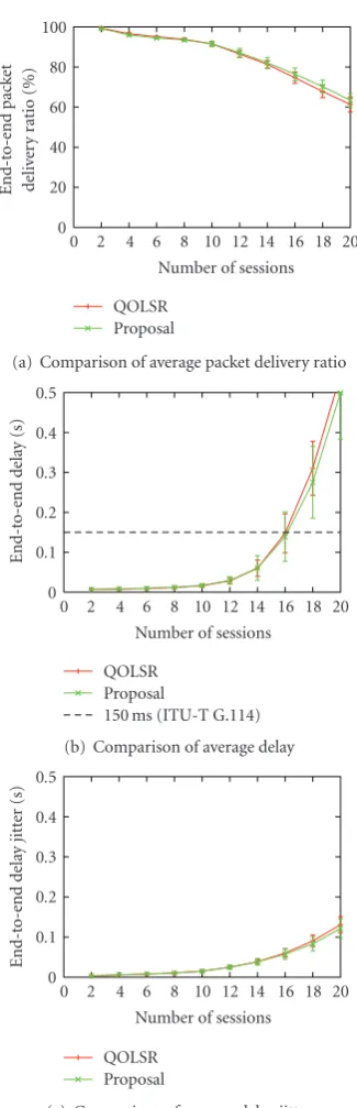
Figure 6: Results of the simulation I (simulation area: 6000 ×
6000 m, number of nodes: 100, broadcast rate: 6 Mb/s, packet size: 1292 bytes).
on QOLSR selects MPRs in the descending order of total available bandwidth on all real-time channels. In the case of a tie, a node with maximum number of uncovered 2-hop neighbors is chosen as an MPR. Each node propagates control messages via the selected MPRs on the best-effort channel to manage network topology. As in our proposal, QOLSR works on best-effort channel and we assume that the physical topology of real-time channels is the same as that constructed based on control messages exchanged on
the best-effort channel. We had disabled our LR (QoS-aware logical routing) when QOLSR (QoS-(QoS-aware physical routing) was running while we kept our SW active to obtain bandwidth information used for MPR and channel selection. As a physical (IP) routing protocol, QOLSR was running instead of our OLSR in the QOLSR evaluation.
4.4. Simulation I—General Topology. We evaluated the per-formance of our proposal on a general topology. We accom-modated 10 random seeds; that is, we carried out 10 simula-tion runs for each number of sessions. Placing nodes depends on the random seeds and nodes are randomly distributed. Because of the density, all nodes have at least one node in the transmission range at rate of 6 Mb/s. We should note here that each node can communicate at higher bit-rate when the distance between nodes is short and the radio can receive clearly. Results on the average end-to-end packet delivery ratio, the average end-to-end delay, and the average delay jitter are shown in Figure 6. We can see from Figure 6(a)
that the average end-to-end packet delivery ratio is similar between our proposal and QOLSR, for example, 91.5% (95% confidence interval, 90.1% to 92.9%) with our proposal and 91.5% (95% confidence interval, 90.5% to 92.6%) with QOLSR for 10 sessions, or little lower in QOLSR for more than 12 sessions. From Figures6(b)and6(c), our proposal is also slightly superior to QOLSR in terms of the average delay and the average delay jitter. Although our proposal not only needs additional LR header for logical routing but establishes about 1.3 times as long path in the number of physical hops, we conclude that our proposal performs well as QOLSR.
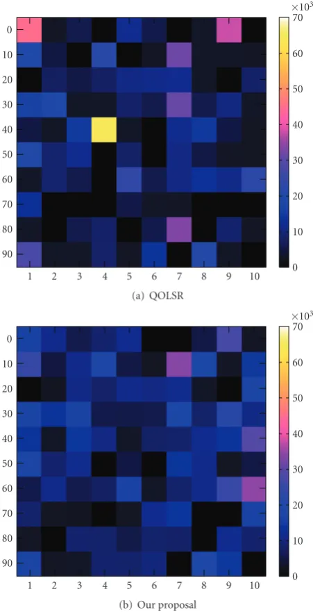
While the performance is almost identical among the proposal and QOLSR, the proposal has an advantage in load distribution. InFigure 7, the total numbers of transmitted MAC frames of all interfaces at nodes on a random seed are illustrated. Each of cells corresponds to a node. The sum of values on thexandyaxes indicates the node identifier, that is, node number. It is noticed that node 44 is heavily loaded with QOLSR (Figure 7(a)), whereas the load is relatively distributed over the whole network with our proposal
(Figure 7(b)). From quantitative viewpoints, the average
variance of transmitted MAC frames per node is 113×106
in Figure 7(a) while it is 55.8× 10⁶ in Figure 7(b). The
average fairness index is 0.39 inFigure 7(a)and it is 0.62 in
Figure 7(b). The fairness index f of 100 nodes is derived by
the following equation:
wherexiis the value of transmitted MAC frames at nodei.
The fairness index 1 means that nodes are used equally. From these results, we can say that our proposal compensates the performance degradation caused by taking a longer physical path with avoiding congested links and balancing the load over the whole network.
10
Figure7: Comparison of total number of transmitted MAC frames.
keeping a certain distance, we first divided the region into 100 cells and placed nodes at random location one per cell. We accommodated other 10 random seeds; that is, we carried out 10 simulation runs for each number of sessions. Furthermore, taking into account the fact that video sessions are not established among arbitrary pairs of nodes, but between a specific pair of nodes, we fixed source and desti-nation nodes during a simulation run. An example of node placement is shown inFigure 8, where filled circle at lower left cell indicates the source node and one at upper right cell indicates the destination node. Because of the regularity of node placement, a node has at least one neighbor within the distance of 863 m and thus we set the broadcasting data rate at 12.0 Mb/s. Results are shown inFigure 9.
We can see that the proposal can accommodate more sessions than QOLSR keeping the high packet delivery ratio
6000
Figure8: Node placement of one case of the simulation II.
in Figure 9(a). Up to 4 sessions, both of the proposal and
QOLSR could achieve the packet delivery ratio of about 97%. However, when the amount of traffic further increases, the performance of QOLSR deteriorates more rapidly than the proposal for the concentration of traffic. For example, with 6 sessions, the packet delivery ratio is about 94.9% (95% confidence interval, 93.4% to 96.4%) with the proposal and about 83% (95% confidence interval, 81.5% to 85.4%) with QOLSR. The difference is more remarkably in the delay in
Figure 9(b). When we see the delay jitter inFigure 9(c), there
is a crossing point at around 11 sessions. In a heavily loaded network, that is, more than 6 sessions, the proposal outper-forms QOLSR by distributing traffic over the whole network by the logical routing. The number of sessions near the delay requirement for interactive voice communication, that is, 150 millisecond (ITU-T G.114 about one-way transmission time), increases from 8 with QOLSR to 10 with the proposal. From these results, we consider that our proposal is effective especially for real-time multimedia applications which may exhaust the capacity of particular wireless links, such as high-quality P2P video conferencing and remote monitoring with multiple cameras and single monitoring point.
5. Practical Experiments and Discussions
We implemented the proposal on a real wireless ad-hoc net-work and conducted practical experiments to verify the prac-ticality and applicability of the proposal. In this section, we describe the experimental system and the obtained results.
20
(a) Comparison of average packet delivery ratio
20
150 ms (ITU-T G.114) 0
(b) Comparison of average delay
20
(c) Comparison of average delay jitter
Figure 9: Results of the simulation II (simulation area: 6000×
6000 m, number of nodes: 100, broadcast rate: 12 Mb/s, packet size: 1292 bytes).
We set three interfaces to the ad-hoc mode and configured one interface among them as best-effort channel and the other two as real-time channels. Since IEEE 802.11g has three orthogonal channels by being separated by at least 25 MHz to avoid interchannel interference, we assigned 2.412 GHz (numbered as channel 0) to best-effort channel and 2.442 GHz (channel 1) and 2.472 GHz (channel 2) to real-time channels.
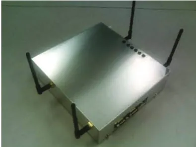
Figure10: The ad-hoc wireless relay node.
A node is equipped with SH7780 (SH-4A) 32-bit RISC MPU and 64 MB flash memory. On the node, Linux OS version 2.6.10 is running with GNU C library version glibc-2.3.3. Due to low capacity of flash memory, BusyBox, that is, single small executable file supporting many common UNIX utilities, is installed. So that several modules running on a node could share the information on an embedded system with very limited memory space, we developed a semaphore module and realize a shared memory mechanism. Similarly to a regular embedded system, a node supports only minimum modules or APIs by default. Therefore, we rebuilt the kernel so that it supports a semaphore module and rewrote the start-up section of the flash memory. We also developed the LR, SW, and OLSRv2 modules. These modules were cross-compiled, installed, and set to run automatically on boot. To avoid the performance degradation for exclusive memory access, we should have carefully determined the locking duration of each access.
To assist smooth experimentation, we developed addi-tional applications for logging experimental data. It is necessary for performance evaluation to record system and communication statuses, that is, when and what kind of message was transmitted on what node, and when the message was received on what node. Because of the low MPU performance, it has been hard to adjust the system clocks for all the nodes, that is, the system clock gains according to the system load. To deal with this problem, our developed applications recorded these statuses per node every second with minimum interruption to the system. After the end of an experiment, we gathered the recorded log files to our computation server via an ethernet connection.
Because of these severe limitations on the architecture and the device, the obtained performance was not as high as expected as will be shown later. However, we think that we could successfully confirm the behavior of our proposal in an actual operating environment.
60 m
50
m
A
S B
D
Figure11: Experimental topology.
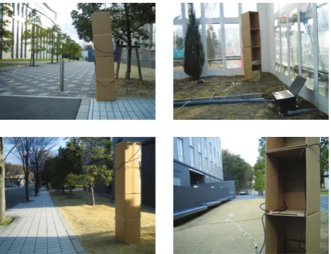
Figure12: Node placement on practical experiments.
each channel was separated by 30 MHz to avoid interchannel interference, a channel might be affected by other channels. In our preliminary experiments, we found that there was radio interference between electromagnetic waves emitted from antennas, but electromagnetic waves also emitted from antenna cables. Since the interference from antennas and antenna cables could be controlled by separating them by more than 20 cm, we built an antenna tower by cardboard boxes as shown inFigure 13to achieve the separation. A node was put in the second lowest box as shown inFigure 13(a)
and antennas were fixed on the side at the different height as shown inFigure 13(b).
Nodes S and D are source and destination node, respec-tively. The distance between two neighboring nodes, that is, S-A, S-B, A-D, and B-D is about 50–60 m. Solid lines indicate physical links. The nodes had possibilities to connect links between S-D or A-B at the good condition of best-effort channel, but the nodes might not construct a link between S-D or A-B at our experiments. Assuming VoIP traffic, we configured the source node to generate 64 kb/s CBR traffic per session. In practical experiments, source node S generated a new session every 5 s and sessions kept alive until the end of each experiment. At the beginning of measurement, network interfaces were operating and
(a) Front sides of antenna tower (b) Rear side of antenna tower Figure13: Antenna tower.
200 175 150 125 100 75 50 25 0
Time (s) Data rate
Expected data rate 0
2 4 6 8 10 ×103
Re
ce
iv
ed
d
at
a
ra
te
(b
yt
es
per
sec
ond)
Figure14: Data reception rate per session at node D.
200 175 150 125 100 75 50 25 0
Time (s) Delay jitter
0.001 0.01 0.1 1
R
ec
ei
ved
data
dela
y
jitt
er
(s)
Figure15: Delay jitter per session at node D.
OLSRv2 was fully functional. The node S started a new session every 5 seconds.
Figure 14shows the data reception rate and the expected
data reception rate, which is equal to 8600 bytes per second (64 kb data traffic + IP header). Until about 35 s, the data reception rate per session was as high as the expected data reception rate and the packet delivery ratio was higher than
98%.Figure 15shows the delay jitter per session. Figures16,
Channel 1, channel 2
Figure16: Transmission data rate per channel at node S.
Channel 1, channel 2
Channel 0
Figure17: Transmission data rate per channel at node A.
Channel 1,
Figure18: Transmission data rate per channel at node B.
data rate at source node S, intermediate nodes A and B, respectively. InFigure 16, lines for the data transmission rate on channels 1 and 2 overlap with each other. This implies that the node S, that is, source node, evenly distributed real-time packets among these two real-time channels by observing the channel usage. The nodes A and B, that
User
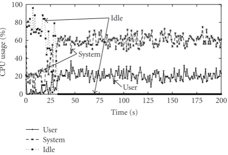
Figure19: Transition of CPU usage at node S.
is, intermediate nodes, also used real-time channels in a balanced manner as shown in Figures17and18. Since the node S started a new session every 5 seconds, we can see the stepwise increase in the data transmission rate (Figure 16).
For the first 7 sessions, we can see in Figure 15 that the delay jitter was as small as 20 millisecond. A physical path from node S to D established by OLSRv2 was S-A-D. However, as can be seen in Figures17and18, nodes A and B were almost equally used by load balancing of logical routing. From the timing of increase in the transmission data rate in Figures17and18, it can be said that the LR on node S chose the path S-A-D for the first two sessions and then moved to the path S-B-D for the following four sessions. Since the advertising period of estimated channel information is 2 seconds and the propagation period of TC message is 5 seconds, there are few seconds of time lag for updated the Extended Topology Set that is used for logical routing.
As the number of sessions increased over 8 at 35 s, the data reception rate per session suddenly deteriorated
(Figure 14) and the delay jitter exponentially increased
(Figure 15). The reason for this can be explained by
Figure 19, where the transition of CPU usage on node S is
depicted. The ratio of idle CPU dropped to zero at 35 s and was kept zero since then. It implies that the drop of data reception rate was caused by full utilization of poor CPU resource of node S.
6. Conclusion
MPU. These are our future research works, and we are also going to conduct large scale experiments.
Acknowledgment
This research was supported in part by “Special Coordina-tion Funds for Promoting Science and Technology: Yuragi Project” and “Global COE (Centers of Excellence) Program” of the Ministry of Education, Culture, Sports, Science and Technology, Japan.
References
[1] J. Li, C. Blake, D. S. J. Couto, H. I. Lee, and R. Morris, “Capacity of ad hoc wireless networks,” inProceedings of the Annual International Conference on Mobile Computing and
Networking (MobiCom ’01), pp. 61–69, July 2001.
[2] S. H. Shah, K. Chen, and K. Nahrstedt, “Available band-width estimation in IEEE 802.11-based wireless networks,”
inProceedings of the ISMA/CAIDA Workshop on Bandwidth
Estimation (BEst ’03), December 2003.
[3] S. Chakrabarti and A. Mishra, “QoS issues in ad hoc wireless networks,”IEEE Communications Magazine, vol. 39, no. 2, pp. 142–148, 2001.
[4] H. Badis, A. Munaretto, K. A. Agha, and G. Pujolle, “QoS for ad hoc networking based on multiple metrics: bandwidth and delay,” in Proceedings of the IFIP-TC6 International Conference on Mobile and Wireless Communications Networks
(MWCN ’03), pp. 15–18, October 2003.
[5] R. Guimar˜aes, J. Morillo, L. Cerd`a, J. Barcel ´o, and J. Garc´ıa, “Quality of service for mobile ad-hoc networks: an overview,” Tech. Rep., Polytechnic University of Catalonia, July 2004. [6] L. Hanzo and R. Tafazolli, “A survey of QoS routing solutions
for mobile ad hoc networks,”IEEE Communications Surveys
and Tutorials, vol. 9, pp. 50–70, 2007.
[7] A. Adya, P. Bahl, J. Padhye, A. Wolman, and L. Zhou, “A multi-radio unification protocol for IEEE 802.11 wireless networks,”
inProceedings of the 1st International Conference on Broadband
Networks (BroadNets ’04), pp. 344–354, July 2004.
[8] A. Nasipuri, J. Zhuang, and S. R. Das, “A multichannel CSMA MAC protocol for multihop wireless networks,” inProceedings of the IEEE Wireless Communications and Networking
Confer-ence (WCNC ’99), pp. 1402–1406, September 1999.
[9] A. Tzamaloukas and J. J. Garcia-Luna-Aceves, “A receiver-initiated collision-avoidance protocol for multi-channel net-works,” in Proceedings of the IEEE Conference on the IEEE
Computer and Communications Societies (INFOCOM ’01), vol.
1, pp. 189–198, April 2001.
[10] Y. Liu and E. Knightly, “Opportunistic fair scheduling over multiple wireless channels,” inProceedings of the IEEE Con-ference on the IEEE Computer and Communications Societies
(INFOCOM ’03), vol. 2, pp. 1106–1115, April 2003.
[11] J. So and N. Vaidya, “Multi-channel MAC for ad hoc networks: handling multi-channel hidden terminals using a single transceiver,” inProceedings of the ACM International Symposium on Mobile Ad Hoc Networking and Computing
(MobiHoc ’04), pp. 222–233, May 2004.
[12] A. Raniwala and T.-C. Chiueh, “Architecture and algorithms for an IEEE 802.11-based multi-channel wireless mesh net-work,” in Proceedings of the IEEE Conference on the IEEE
Computer and Communications Societies (INFOCOM ’05), vol.
3, pp. 2223–2234, March 2005.
[13] P. Kyasanur and N. H. Vaidya, “Routing and link-layer protocols for multi-channel multi-interface ad hoc wireless networks,”ACM SIGMOBILE Mobile Computing and
Commu-nications Review, vol. 10, pp. 31–43, 2006.
[14] N. Niranjan, S. Pandey, and A. Ganz, “Design and evaluation of multichannel multirate wireless networks,”Mobile Networks
and Applications, vol. 11, no. 5, pp. 697–709, 2006.
[15] R. de Renesse, M. Ghassemian, V. Friderikos, and A. H. Aghvami, “QoS enabled routing in mobile ad hoc networks,”
in Proceedings of the IEEE International Conference on 3G
Mobile Communication Technologies (3G ’04), pp. 678–682,
October 2004.
[16] R. Sivakumar, P. Sinha, and V. Bharghavan, “CEDAR: a core-extraction distributed ad hoc routing algorithm,”IEEE Journal
on Selected Areas in Communications, vol. 17, no. 8, pp. 1454–
1465, 1999.
[17] H. Badis and K. A. Agha, “Quality of service for ad hoc optimized link state routing protocol (QOLSR),” Mobile Ad hoc Networking (MANET) Internet-Draft, March 2007. [18] S. Kajioka, N. Wakamiya, M. Murata, et al., “Proposal,
implementation, and evaluation of a QoS-aware routing mechanism for multi-channel multi-interface ad-hoc net-works,” inProceedings of the 4th International Conference on
Wireless and Mobile Communications (ICWMC ’08), pp. 167–
172, July 2008.
[19] T. H. Clausen, C. M. Dearlove, and P. Jacquet, “The optimized link state routing protocol version 2 (OLSRv2),” Mobile Ad hoc Networking (MANET) Internet-Draft, March 2009. [20] K. Xu, K. Tang, R. Bagrodia, M. Gerla, and M. Bereschinsky,
“Adaptive bandwidth management and QoS provisioning in large scale ad hoc networks,” inProceedings of the IEEE Military
Communications Conference (MILCOM ’03), vol. 2, pp. 1018–
1023, October 2003.
[21] C. Sarr, C. Chaudet, G. Chelius, and I. G. Lassous, “Bandwidth estimation for IEEE 802.11-based ad hoc networks,” IEEE
Transactions on Mobile Computing, vol. 7, no. 10, pp. 1228–
1241, 2008.
[22] M. Saghir, T.-C. Wan, and R. Budiarto, “A new cross-layer framework for QoS multicast applications in mobile ad hoc networks,” International Journal of Computer Science and
Network Security, vol. 6, pp. 142–151, 2006.
[23] A. Qayyum, L. Viennot, and A. Laouiti, “Multipoint relaying for flooding broadcast messages in mobile wireless networks,”
inProceedings of the Hawaii International Conference on System
Sciences (HICSS ’02), pp. 3866–3875, January 2002.
[24] R. A. Gu´erin, A. Orda, and D. Williams, “QoS routing mechanisms and OSPF extensions,” inProceedings of the IEEE
Global Telecommunications Conference (GLOBECOM ’97), vol.
3, pp. 1903–1908, November 1997.
[25] Scalable Network Technologies, Inc., “QualNet 4.0,” http:// www.scalable-networks.com.
[26] K.-P. Shin, Y.-D. Chen, and C.-C. Chang, “Adaptive range-based power control for collision avoidance in wireless ad hoc networks,” inProceedings of the IEEE International Conference
on Communications (ICC ’07), pp. 3672–3677, June 2007.
[27] K. Xu, M. Gerla, and S. Bae, “How effective is the IEEE 802.11 RTS/CTS handshake in ad hoc networks?” in Proceedings of the IEEE Global Telecommunications Conference
(GLOBE-COM ’02), vol. 1, pp. 72–76, November 2002.
[28] J. Jun, Capacity estimation of wireless mesh networks, M.S. thesis, Graduate Faculty of North Carolina State University, November 2002.