Designing and Structural Analysis of Vehicle Chassis Made
Of Composite Material
S.Kranthi Goud
& Virajee Reddy T
1
PGStudent, Department of Mechanical Engg, Vidya Jyothi Institute of Technologyjntuh Hyderabad
2assistant
Professor, Department Of Mechanical Engg. Vidya Jyothi Institute Of Technologyjntuh,
Hyderabad
ABSTRACT
The skeleton layout outlines the establishment of a staggering vehicle; its rule work is to safely pass on the most outrageous load for all arranged working conditions. This paper depicts plan and examination of overpowering vehicle body. Weight reducing is right now the essential issue in auto organizations. In the present work, the estimations of a current significant vehicle suspension of a TATA 2515EX vehicle is taken for exhibiting and examination of a staggering vehicle case with three particular composite materials particularly, Carbon/Epoxy, E-glass/Epoxy and S-E-glass/Epoxy subjected to an indistinct weight from that of a steel skeleton. The blueprint impediments were stresses and redirections. The three unmistakable composite overpowering vehicle skeleton have been shown by thinking about three different cross-regions. For endorsement the arrangement is done by applying the vertical weights following up on the even novel cross sections. Writing computer programs is used as a piece of this work CATIA V5 for illustrating, ANSYS 14.5 for examination.
Catchphrases: overpowering vehicle skeleton, Static examination, Carbon/Epoxy, E-glass/Epoxy and S-glass/Epoxy,
1.1 INTRODUCTION
The landfill truck utilized for transporting free materials in mining and development. A regular dump truck is outfitted with a using pressurized water - worked suspension with shut box structure skeleton, a body which is situated at the highest point of the case. The undercarriage bolstered at the front and back side suspension of the truck. The motivation
behind the body is lifted back side of the vehicle, which is to store the materials on the ground. Skeleton is a vital piece of the heap conveying individual from a back dump truck over which the whole gear is organized. Frame going about as an auxiliary help for control prepare components and furthermore empowers the landfill body conveying full payload. The frame is neither a functional nor a replaceable part the extent that the life expectancy of the vehicle is concerned. The life expectancy of a skeleton must be equivalent to or in excess of 30,000 running hours under typical working state of the vehicle. To expand the weariness life and its proliferation over the suspension and to maintain a strategic distance from split, it is totally important to have a discretionary plan to withstand the total load under typical conditions. For this reason, it is important to fortify the edge and to expand the wellbeing variable of the case for an expanded weariness life. 2 The case improvement forms in the car and transport hardware enterprises are
The cost and unpredictability of this approach makes its application unrealistic for low volume ''extraordinary" vehicles. It has been that shown direct static 3 push appropriation, straightforward weakness estimations and static limited component examination, can be utilized to accomplish satisfactorily precise exhaustion life forecast of a car frame.
1.2 CLASSIFICATION OF TRUCK
reasonable for pulling. Definitions differ contingent on the sort of truck and its application.
Table 1.1 Truck Classifications
Category Gross vehicle weight
Representative vehicles
Light duty truck
Between 1 to 7 Ton
Car, Auto and Van
Medium duty truck
Between 10 to 20 Ton
Bus & Lorry
Heavy duty truck Above
30 Ton Dumper & Motor Grader
Trucks can be classified as Light duty truck, Medium duty truck and Heavy duty truck. They
are presented in Table 1.1.
1.2.1 Standard Dump Truck
The standard dump truck is a full truck chassis with a dump body mounted onto the frame. The dump body is raised by a hydraulic ram lift that is mounted forward of the front bulkhead, normally between the truck cab and the dump body. The standard dump truck also has a front axle, and one or more rear axles, which normally have dual wheels on each side. The common configurations for standard dump trucks are six and ten wheelers.
1.2.2 Transfer Dump Truck
The transfer dump truck is easily recognizable through the noise made during transfer. A standard dump truck pulls a separate trailer which can be loaded with sand, asphalt, gravel, dirt, etc. The box or aggregate container on the trailer is powered by an electric motor, which rides on wheels and rolls off of the trailer and into the main dump box. The biggest advantage of this configuration is that payload capacity maximized manufacturability of the short and nimble dump truck standards.
1.2.3 Semi Trailer Dump Truck
The semi end dump truck is a tractor trailer combination where the trailer itself contains the hydraulic hoist. The average semi end dump truck has a 3 axle tractor that pulls a 2 axle semi trailer. The rapid unloading is the main advantages of semi trailer dump truck.
1.2.4 Semi Trailer Bottom Dump Truck
A bottom dump truck is a 3 axle tractor that pulls a 2 axle trailer with a clam shell type dump gate in the belly of the trailer. The biggest advantage of a semi bottom dump truck is its ability to lay material in a wind row unlike the double and triple trailer configurations. This type of truck is also maneuverable in reverse as well.
1.2.5 Double and Triple Bottom Dump Truck
The double and triple bottom dump trucks consist of a 2 axle tractor pulling a semi axle semi trailer and an additional trailer. These types of dump trucks allow the driver to lay material in wind rows without the material having to leave the cab or stop the truck. However biggest disadvantage is the difficulty in going in reverse.
COMPOSITE MATERIALS:
weight-ratios of these composite materials are markedly superior to those ofmettalic materials.
REVIEW OF LITERATURE
Smita, C.Saddu [1] et. al Weight reduction is now
day’s main issue in the automobile industry.
Reducing weight while increasing or maintaining
strength of product is getting to be highly important.
The automobile industry has shown increasing
interest in the replacement of steel spring with
composite leaf spring due to high strength to weight
ratio. Advanced composite materials offer significant
advantages in strength, stiffness, high natural
frequency and light weight relative to conventional
metallic materials. This paper describes the analysis
of steel and composite material leaf spring. Then
these results are compared with that of the
experimental results.
Juvvi Siva Nagaraju U. HariBabu [2] et. al In the
case of vehicles, the term chassis means the frame
plus the "running gear" like engine, transmission,
driveshaft, differential, and suspension.
Over time, other materials have come into use, the
majority of which have been is Steel &Aluminum. In
this paper traditional materials are replaced with
composite materials[Carbon Epoxy and E- glass
epoxy].
SandipGodseD.A.Patel[ 3 ] et. Al Chassis is a major
component in a vehicle system. This work involved
static analysis todetermine key characteristics of a
chassis. The staticcharacteristics include identifying
location of high stress area.Mathematical calculations
were carried out to validate the staticanalysis.
K.Rajasekar,R.SaravananP[4] et. Al Chassis is the
mostimportant structural member in the On-Road
vehicles. In order toovercome more failure in the
chassis structure and ensure thesafety, the variable
section chassis structure has to be designedbased on
the variable loads along the length of the vehicle.
Thepresent study reviewed the literature on chassis
design andpresented the findings in the subsequent
sections.
SPECIFICATIONOF EXISTING HEAVY
The details of processing of the Polymeric composites
and the experimental procedures followed for their
mechanical characterization. The Polymeric
composites materials used inthis work are
1. E-glass/Epoxy
2. S-glass /Epoxy
3. Steel
4.Carbon/Epoxy
E-glass /Epoxy
E-glass or electrical grade glass was originally
developed for standoff insulators for electrical wiring.
It was later found to have excellent fiber forming
capabilities and is now used almost extensively as the
reinforcing phase in the material commonly known as
fiber glass.
3.1VEHICLE CHASSIS:
Table 1 shows the specifications of a TATA 2515EX
OF STEEL HEAVY vehicle. The typical chemical
composition of the material is 0.565C, 1.8% Si,
0.7%Mn, 0.045%P and 0.045% S.
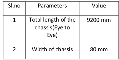
Table: 1 Specifications of heavy vehicle chassis
Sl.no Parameters Value 1 Total length of the
chassis(Eye to Eye)
9200 mm
3 Thickness of chassis
5.5 mm
4 Front cabin chassis length
2400 mm
5 Front cabin chassis area
492800 mm2 6 Front cabin
chassis
20620 N
applying load 7 Backbody chassis
length
5900 mm
8 Backbody chassis area
1200000 mm2 9 Backbody chassis
applying
206200
Load N
10 Young’s Mod Chassis
2.1e5 N/mm2 11 Density of steel
chassis
7.86*10-6 N/mm2 INTRODUCTION TO CAD/CAM/CAE
The Modern world of design, development,
manufacturing so on, in which we have stepped can’t
be imagined without interference of computer. The
usage of computer is such that, they have become an
integral part of these fields. In the world market now
the competition in not only cost factor but also
quality, consistency, availability, packing, stocking,
delivery etc. So are the requirements forcing
industries to adopt modern technique rather than This
penetration of technique concern has helped the
manufacturers to
a) Increase productivity
b) Shortening the lead-time
c) Minimizing the prototyping expenses
d) Improving Quality
e) Designing better products
CAD: Computer Aided Designing (Technology to create, Modify, Analyze orOptimize the design using computer.
CAE: Computer Aided Engineering (Technology to analyze, Simulate or Studybehaviour of the cad model generated using computer.
CAM: Computer Aided Manufacturing (Technology to Plan, manage or controlthe operation in manufacturing using computer.
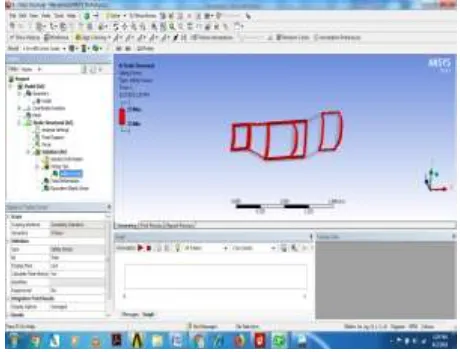
DESIGNING
Figure2VEHICLE CHASSIS side view
Figure3VEHICLE CHASSIS muliti section
INTRODUCTION TO FEA
Finite Element Analysis (FEA) was first developed in
1943 by R. Courant, The paper centered on the
"stiffness and deflection of complex structures". By
the early 70's, FEA was limited to expensive
mainframe computers generally owned by the
aeronautics, automotive, defense, and nuclear
industries. Since the rapid decline in the cost of
computers and the phenomenal increase in computing
power, FEA has been developed to an incredible
precision. Present day supercomputers are now able
to produce accurate results for all kinds of
parameters.
TABLENO.1.PROPERTIESOFEGLASS/EPOXY
S. No Properties
1
Applying vertical force on a cabin
2
Applying vertical force on
body 9417 N
3
Tensile modulus along
X-direction (Ex), Mpa 39000
4 Tensile modulus along Y- 8600
direction (Ey), Mpa
5
Tensile modulus along
Z-direct ion (Ez), Mpa 8600
6
Tensile strength of the
material, Mpa 1080
7
Co mpressive strength of the
material, Mpa 890
8
Shear modulus along
XY-direct ion (Gxy), Mpa 3800
9
Shear modulus along YZ-d
irection (Gyz ), Mpa 3800
10
Shear modulus along ZX-d
irection(Gzx), Mpa 3800
11
Poisson ratio along XY-d
irection (NUxy) 0.28
12
Poisson ratio along YZ
-direction (NUyz) 0.06
13
Poisson ratio along
ZX-direction (NUzx) 0.28
14
3 -6
Mass density of the material
(ρ), 2.1x10
TABLE NO. 2. PROPERTIES OF S GLASS/EPOXY
S.No Properties Value
1 Applying vertical force on a cabin 6278 N 2 Applying vertical force on body 9417 N
3
Tensile modulus along X-direction (Ex),
Mpa 43000
4
Tensile modulus along Y-direction (Ey),
Mpa 8900
5
Tensile modulus along Z-direct ion (Ez),
Mpa 8900
6 Tensile strength of the material, Mpa 1280
7
Co mpressive strength of the material,
Mpa 690
8
Shear modulus along XY-direct ion
(Gxy), Mpa 4500
9
Shear modulus along YZ-d irection (Gyz
), Mpa 4500
10
Shear modulus along ZX-d irection
(Gzx), Mpa 4500
11
Poisson ratio along XY-d irection
(NUxy) 0.27
12
Poisson ratio along YZ -direction
13 Poisson ratio along ZX-direction (NUzx) 0.27
14 Mass density of the material (ρ), 3 2x10⁻⁶
ANALYS IS OF PRESS URE CALCULATIONS Cabin chassis Pressure Calculations:
Assumptions of load calculations Tata ace self weight =600 kgs
Self weight +carriage weight load = 600+1000=1600 kgs Ribs area =600*120=7200 mm2
3ribs area =72000* 3=216000 mm2 Rails area =1960*120 =235200 mm2 2rails area =235200*2 =470400 mm2
3ribs area + 2rails area =470400+216000=6864000 Total body pressure =9417.65/ 686400=0.01372 N/ mm2
Body chassis Pressure Calculations: Body chassis pressure calculations Body load =960*9.81=9417.6 N
Body total area=body 3ribs area=body rails area Cabin chasis pressure calculations
Cab in load =640kgs =640*9.81=6278.4 N
Cab in total area =cabin two ribs area +cabin two rails area Cab in two ribs area =(400*120)*2=96000mm2 Cabin t wo rails area =530*240 =127200 mm2 Cab in total area =96000+127200 =223200 mm2
Cabin total pressure =cabin load /cabin total area =6278.4/ 223200 =0.028129 N/ mm2
Total body pressure =9417.65/ 686400=0.01372 N/ mm2
ANALYSIS STEEL
Figure.1. stress pattern for steel chassis
The unifo rm load is applied at the edges of the chassis. And the maximum m value is 394.803 N/
mm2 and min imu m value is 43.8711N/ mm2.
Figure. 2. Dis placement pattern for steel chassis
Analysis e-glass/epoxy
Figure..Stress pattern for E-glass-epoxy chassis
Figure.6. stress pattern for E-glass/epoxy chassis
The unifo rm load is applied at the edges of the chassis.And the maximu m displacement value is 19.25 mm and min imu m d displacement value is 2.139 mm.
analysis carbon/epoxy
Stress forCARBON/EPOXY chassis
Figure. stress pattern for chassis
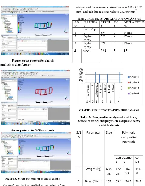
analysis s-glass/epoxy
Stress pattern for S-Glass chassis
Figure.3. Stress pattern for S-Glass chassis
. The unifo rm load is applied at the edges of the
chassis.And the maximu m strees value is 323.488 N/ mm2 and min imu m strees value is 35.96N/ mm2 .
Table.3. RES ULTS OBTAINED FROM ANS YS
S.N MATERIA STRES F.O. DISPLA CEM E
O L S S NT
1
carbon/epox
y 394 6 14 mm
2 S-glass 323 4 17 mm
epoxy
3 E-glass 326 3 19 mm
epoxy
4
steel
384
5
15
GRAPHS:RES ULTS OBTAINED FROM ANS YS
Table 3. Comparative analysis of steel heavy vehicle chassis& and polymeric composite heavy
vechicle chassis
S.N
O
Parameter
Stee
l
Polymeric
composite
materials
Comp
1
Comp
2
Com
p 3
1
Weight (kg)
608.
35
122.
28
162.
53
154.
71
2
Stress(N/mm
162.
55.1
34.5
34.3
0 100 200 300 400 500
MAT
ERIA
L
carb
o
n
/e
p
…
S-glas
s
ep
o
xy
E-gl
as
s
ep
o
xy
stee
l
S.N O 1 2 3 4
2
)
89
51
06
22
3
Displacemen
t(mm)
2.62
8
1.51
2
1.51
2
2.40
4
GRAPHS:
Comparative analysis of steel heavy vehicle chassis& and polymeric composite heavyvechicle chassis
CONCLUSIONS
This experimental investigation of mechanical
behavior of the Steel, E -Glass/Epoxy, S Glass/Epoxy
carbon/epoxy Polymeric composites Chassis leads to
the following conclusions:
1. Observe the all results and to compare the
polymeric composite light vehicle chassis
and steel light vehicle chassis with respect to
weight, stiffness and strength.
2. By employing a polymeric composite light
vehicle chassis for the same load carrying
capacity, there is a reduction in weight of
30%~35.8%, natural frequency of polymeric
composite light vehicle chassis are
35.82%~38.8% higher than steel chassis and
30~33.8% stiffer than the carbon/epoxy
chassis.
3. From the results, it is observed that the
polymeric composite heavy vehicle chassis
is lighter and more economical than the
conventional carbon/epoxy chassis with
similar design specifications.
REFERENCES
[1]. C. Karaoglu, N. S. Kuralay, Stress analysis
of a truck chassis with riveted joints, Finite Elements
in Analysis and Design, 38, (2002), 1115–1130.
[2]. K.W. Poh, P.H. Dayawansa, A.W.
Dickerson, I.R. Thomas, Steel membrane floors for
bodies of large rear-dump mining trucks, Finite
Elements in Analysis and Design 32, (1999),
141-161.
[3]. K. J. Buhariwala and J. S. Hansen,
"Dynamics of Viscoelastic Structures", AIAA
Journal, Vol. 26, February 1988, pp 220-227.
[4].
10.1 Books:[5]. Nitin S. Gokhale- Practical Finite Element
Analysis.
[6].
Autar K. Kaw. Mechanics of CompositeMaterials. 2e, Taylor & Francis Group, LLC, 2006.
0 200 400 600 800
Comp 1Comp 2Comp 3 Steel Polymeric
composite materials
1 Weight (kg)
2