Available online: http://edupediapublications.org/journals/index.php/IJR/ P a g e | 975
Enhancement of Solar Farm Connectivity with Smart PV
Inverter PV STATCOM
K.Ramudu1, M.S ridhar2, Dr.A.Mallikarjuna Prasad3
1
P.G. Scholar, 2Guide, Assistant Professor, 3Head of the Department
1,2,3
BRANCH : P&ID(EEE)
1,2,3
GEETHANJALI COLLEGE OF ENGINEERING AND TECHNOLOGY
EM AIL.ID : [email protected]
ABSTRACT
This paper presents an innovative smart PV inverter control as STATCOM (PV-STATCOM) for obviating the need for a physically connected STATCOM in a distribution network for controlling steady state voltage and temporary over voltages (TOVs) resulting from unsymmetrical faults. Two 10 M W PV solar systems are already connected in the distribution feeder of a utility in Ontario, Canada. A STATCOM is installed to prevent the steady-state voltage and TOV issues aris ing from the connection of a third 10 M W PV solar farm at same bus. It is demonstrated from PSCAD electromagnetic transient studies that if the proposed PV-STATCOM control is implemented on the incoming third 10 M W PV solar farm, all the above voltage issues are mitigated satisfactorily as required by the utility Grid Code. This proposed smart inverter PV-STATCOM control therefore eliminates the need for
the physical STATCOM, saving an
enormous cost for utilities dealing with voltage rise and TOV issues with grid connected PV systems. Such a control can effectively increase the Distributed Generator hosting capacity of distribution feeders at more than an order of magnitude lower cost under similar network conditions. M oreover, this novel grid support functionality can open new revenue making opportunities for PV solar farms.
Keywords:- Automatic voltage control, Inverters, Reactive power, S teady-state, Photovoltaic power systems, Capacitors
INTRODUCTION
Distributed Generators (DGs) bring several benefits to distribution networks. However, these benefits come along with new challenges. Some of these challenges include steady state overvoltage, temporary overvoltage (TOV), unbalanced voltage, power quality issues such as harmonics, frequent operation of conventional voltage regulators such as load tap changers and capacitor banks, changes in feeder power factor, etc. High penetration of solar farms is known to cause reverse power flows resulting in over voltages at PCC which
potentially limit any future DG
installations. Traditionally, shunt capacitor banks (SCs), on-load tap changers (OLTC) and step type voltage regulators (SVRs) are utilized for voltage control in the distribution systems. However, these devices are slow acting with a response time ranging from seconds to few minutes. M oreover, these devices such as OLTC and SVR operate based on unidirectional flow of power and cannot operate reliably during bidirectional power flows caused by Distributed Generators e.g. solar farms.
Flexible AC Transmission Systems
Available online: http://edupediapublications.org/journals/index.php/IJR/ P a g e | 976
voltage control with a response time of 1-3 cycles with STATCOM being much faster than SVC.
The Ontario Independent Electricity System Operator (IESO) proposed the installation of a -33/+48 M var Static Var Compensator (SVC) to provide the dynamic reactive power requirement of the 100 M W PV solar farm at the Grand Renewable Energy Park (GREP) in Haldimand County, Nanticoke, Ontario. An SVC is proposed to prevent rise
in customer voltage caused by
interconnection of P V solar systems in a Japanese distribution feeder. Small size STATCOMs are also proposed in Japan to mitigate voltage rise issues due to surplus power injected by PV solar farms in distribution feeders. Studies for determining optimal size and location of SVC for improving voltage regulation at different operating conditions of residential PV solar systems connected in an Egyptian distribution feeder are described in. A D-STATCOM is proposed to improve voltage regulation due to variability of power output from PV solar systems in an Australian distribution network.
Four STATCOMs in the range 1-2 M var
have been actually installed in
M assachusetts, USA, at various locations to mitigate feeder voltage rise and voltage fluctuations in a distribution feeder caused by variability of power output from a cluster of 13 M W PV solar systems. A 6 Mvar STATCOM is installed at the substation of 52.5-megawatt (M W) Shams M a’an PV solar project in Jordan to maintain a smooth voltage profile under different network conditions and variable PV output.A case study of a 44 kV distribution feeder with two 10 M W PV solar farms is reported in. Connection of a third 10 M W solar farm failed the power distance test of the utility indicating that voltage issues will be caused by its interconnection. Reconductoring the feeder to improve X/R ratio or relocation of
the PCC of the solar farms to another feeder were considered to be economically unviable solutions. The utility decided to install a STATCOM for regulating the steady state voltage to within utility acceptable limits. It is noted that the conventional symmetrical voltage control provided by SVCs (and STATCOM s)
worsen the problem of Temporary
Overvoltages in an actual transmission ystem in California [17]. Hence a new unsymmetrical control is needed, which is considered in this paper.
Smart inverters have been proposed for PV solar systems to effectively counteract voltage issues. Smart inverter functions such volt/var, volt/watt, off-unity power factor, Low/High Voltage Ride Through, Low/High Frequency Ride Through and Dynamic Reactive Current Injection, etc.
have been demonstrated in field
applications. Grid Codes such as IEEE 1547 have been revised in the interim [22]. The newly proposed smart inverter functions as described in the revised IEEE 1547 (2018) although provide ride through capability but not Temporary Overvoltage mitigation explicitly. A unique control of PV solar farms as STATCOM during nighttime for providing various grid support functions with full inverter capacity and for delivering the same benefits during daytime with PV inverter capacity remaining after real power generation was introduced in 2009. The proposed control, termed PV-STATCOM, was utilized for increasing the connectivity of wind farms and for improving the power transmission capacity. The above control however has a limitation of available reactive power capacity especially during noontime when the inverter is completely utilized for real power generation.
Available online: http://edupediapublications.org/journals/index.php/IJR/ P a g e | 977
only steady state voltage control in the grid by three-phase symmetrical real power generation by PV systems. However, the control strategy proposed in cannot provide mitigation of Temporary Overvoltage (TOV) during unsymmetrical faults which is a major issue in the integration of PV solar farms. For suppressing TOV, an entirely different control is required, which is the main contribution of this paper.
The novelty of this paper is that a new smart inverter PV- STATCOM solution is proposed for mitigating steady state voltage rise and more importantly Temporary Overvoltage caused by high penetration of PV solar systems. Traditionally, to address these issues, dynamic reactive power
compensators such as Static Var
Compensator (SVC) and STATCOM , have not only been proposed, but actually installed in several parts of the world including Canada and USA. In this paper, the effectiveness of the PV-STATCOM technology has been shown on a realistic distribution feeder in Ontario where an actual STATCOM has been installed for steady state voltage control [16]. It is demonstrated that the proposed
PV-STATCOM can provide the same
functionality of steady state voltage control and moreover provide TOV mitigation, thus eliminating the need of the installed STATCOM. The PV-STATCOM solution is highly cost- effective (about 50 times cheaper) compared to actual SVCs and STATCOMs as it utilizes the existing electrical substation infrastructure such as buswork, transformers, breakers, protection systems, of the PV solar system (which are quite similar to those in actual SVCs and
STATCOM installations). The
PV-STATCOM technology can therefore
potentially bring significant cost-savings to utilities in that they may not need to install expensive SVCs or STATCOMs. M oreover, this novel grid support functionality can
open new revenue making opportunities for PV solar farms.
PHOTO VOLTAIC SYSTEM S
Photovoltaic systems (PV system) use solar panels to catechumen sunlight into electricity. An arrangement is fabricated up of one or added photovoltaic (PV) panels, a DC/AC ability advocate (also accepted as an inverter), a tracking arrangement that holds the solar panels, electrical interconnections, and ascent for added components. Optionally it may cover a best ability point tracker (M PPT), array arrangement and charger, solar tracker, activity administration software, solar concentrators or added equipment.
Photovoltaic Cell:
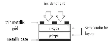
Fig 2.1 Basic PV cell structure
This semiconductor diode has got a p -n alliance which is apparent to light. When aflame by sunlight it generates electric power. PV corpuscle are fabricated up of assorted semiconductor materials. But mono-crystalline silicon and poly-crystalline silicon are mainly acclimated for bartering use.
Photovoltaic module
Available online: http://edupediapublications.org/journals/index.php/IJR/ P a g e | 978
comprise of straightforward front side, embodied P V cell and rear. The front side material is typically comprised of low-iron and treated glass. This is because of the way that some radiation is reflected by the glass cover and casing shadowing and so forth.
Photovoltaic Array
A photovoltaic arrangement (PV system) is a alternation of modules which in about-face is fabricated up of abounding P V beef in alternation or parallel. The ability produced by a individual bore is hardly abundant for bartering use, so modules are affiliated to anatomy arrangement to accumulation the load. M odules can as well be affiliated in alternation to get an added voltage or in alongside to get an added accepted as apparent in Fig. 2.2.
Fig 2.2 Photovoltaic Hierarchy Working of PV cell
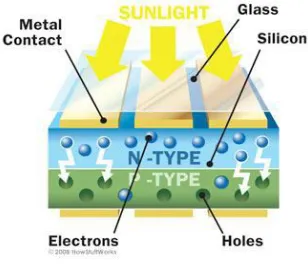
Working of a P V corpuscle is based on the basal assumption of photoelectric effect. Photoelectric aftereffect can be authentic as a abnormality in which an electron gets ejected from the advice bandage as a aftereffect of the assimilation of sunlight of a assertive amicableness by the amount (metallic or non-metallic solids, liquids or gases).So, in a photovoltaic cell, if sunlight strikes its surface, some allocation of the solar activity is captivated in the semiconductor material. If captivated activity is greater than the bandage gap activity of the semiconductor, the electron from valence bandage all-overs to the advice band. By this, pairs of hole-electrons
are created in the aflame arena of the semiconductor. These charge less electrons are affected to move in a accurate administration by the activity of electric acreage present in the PV cells. These abounding electrons constitutes accepted and can be fatigued for alien use by abutting a metal bowl on top and basal of PV cell. This accepted and the voltage (created because of its congenital electric fields) produces appropriate power.
Fig 2.3 Working of PV cell
CHARACTERISTICS OF A PV CELL In a PV appropriate there is basically three important credibility viz. accessible ambit voltage, abbreviate ambit accepted and best ability point. The best admiral that can be extracted from a PV corpuscle are at the best ability points. Usually manufacturers accommodate these ambit in their datasheets for a authentic PV corpuscle or module. By application these ambit we can body a simple archetypal but for added advice is appropriate for designing an authentic model.
Available online: http://edupediapublications.org/journals/index.php/IJR/ P a g e | 979
Photovoltaic systems are acclimated in array
of applications. Angle abandoned
arrangement is a acceptable appliance of P V systems. A angle abandoned arrangement does not accept a account connection. It uses ability as it is produced.
Lighting: The availability of low burden sodium and beaming lights that runs on low ability DC has fabricated PV systems an ideal antecedent for lighting in limited places. PV systems are acclimated to accommodate lighting for artery lights, advice signs, parking lots and homes.
Communications systems: PV systems are acclimated in transmitters, cellular phones, carriage able computers, satellites, adaptable radio systems etc.
Informative signs: Some accessories like artery admonishing alarms, railroad signs, abyssal beacons, aircraft beacons can’t be affiliated to account grids. P V systems are acclimated for these kinds of applications.
Water Pumps: PV achievement can be anon fed to DC pumps. These pumps can be anon operated to accommodate baptize for irrigation, apple baptize accumulation or for livestock.
Vehicles: Solar ability can be used to allegation car batteries.
Refrigeration: PV systems are
acclimated for accumulator of
medicines in limited places.
General use: Solar ability is acclimated in watches, calculators, lanterns, fans, radios and alfresco lights.
Simple PV Systems:
The aforementioned brilliant canicule that dry out plants, accomplish animals thirsty, and calefaction up barrio and cars are aswell acceptable canicule for breeding electricity with photovoltaics. This electricity can be acclimated to ability baptize pumps for irrigation and bubbler wells, and blast admirers for air cooling. For this reason, the a lot of simple PV systems use the dc
electricity as anon as it is generated to run baptize pumps or fans.
These basal PV systems accept several advantages for the appropriate jobs they do. The activity is produced area and if it is needed, so circuitous wiring, storage, and ascendancy systems are unnecessary. Small
systems, beneath 500 watts (W),
counterbalance beneath than 68 kilograms (150 pounds), authoritative them simple to carriage and install. A lot of installations yield alone a few hours. And, although pumps and admirers crave approved maintenance, the PV modules crave alone an casual analysis and cleaning
1.1.PV with Battery Storage
Storing electrical activity makes PV systems a reliable antecedent of electric ability day and night, rain or shine. PV systems with array accumulator are getting acclimated all over the apple to ability lights, sensors, recording equipment, switches, appliances, telephones, televisions, and even ability tools. PV systems with batteries can be advised to ability dc or ac equipment. People who wish to run accepted ac accessories add a ability conditioning accessory alleged an " inverter" amid the batteries and the load. Although a baby bulk of activity is absent in converting dc to ac, an inverter makes P V-generated electricity behave like account ability to accomplish accustomed ac appliances, lights, and even computers.
Working operation
PV systems with batteries accomplish by abutting the PV modules to a battery, and the battery, in turn, to the load. During aurora hours, the PV modules allegation the battery. The array food ability to the amount whenever needed. A simple electrical accessory alleged a allegation ambassador keeps the batteries answerable appropriately and helps prolong their activity by attention them from overcharging or from getting absolutely drained.
Batteries accomplish PV systems
Available online: http://edupediapublications.org/journals/index.php/IJR/ P a g e | 980
crave some maintenance. The batteries acclimated in PV systems are generally agnate to car batteries, but are congenital somewhat abnormally to acquiesce added of their stored activity to be acclimated anniversary day. (They are said to be "deep cycling," like the batteries acclimated on golf carts.) Batteries advised for PV projects affectation the aforementioned risks and appeal the aforementioned attention in administration and accumulator as automotive batteries. The aqueous in apparent batteries should be arrested periodically, and batteries should be adequate from acutely cold.
A solar breeding arrangement with batteries food electricity if it is needed. How abundant electricity can be acclimated afterwards dusk or on blurred canticle is bent by the achievement of the PV modules and the attributes of the array bank. Including added modules and batteries increases arrangement cost, so activity acceptance is anxiously advised to actuate optimum arrangement size. A well-designed
arrangement balances amount and
accessibility to accommodate the user's needs, and can be broadcast if those needs change.
PHOTO VOLTAIC SYSTEM S WITH GENERATORS
When ability have to consistently be accessible or if beyond amounts of electricity than a PV arrangement
abandoned can accumulation are
occasionally needed, an electric architect can plan finer with a PV arrangement to accumulation the load. During the daytime, the PV modules agilely accumulation daytime activity needs and allegation batteries. If the batteries run low, the engine architect runs at abounding power, its a lot of amount and fuel-efficient approach of operation until they are answerable and in some systems, the architect makes up the aberration if electrical appeal exceeds the accumulated achievement of the P V modules and the batteries.
Utility Scale Power
Large-scale photovoltaic power plants, consisting of many PV arrays installed together, can prove useful to utilities. Utilities can build PV plants much more quickly than they can build conventional power plants because the arrays themselves are easy to install and connect together electrically. Utilities can locate PV plants where they are most needed in the grid because siting PV arrays is much easier than siting a conventional power plant. And, unlike conventional power plants, PV plants can be expanded incrementally as demand increases. Finally, PV power plants consume no fuel and produce no air or water pollution while they silently generate electricity.
Unfortunately, PV generation plants have several characteristics that have slowed their use by utilities. Under current utility accounting, PV-generated electricity still costs considerably more than electricity generated by conventional plants, and regulatory agencies require most utilities to supply electricity for the lowest cash cost. Furthermore, photovoltaic systems produce power only during daylight hours and their output varies with the weather. Utility planners must therefore treat a PV power plant differently than they would treat a conventional plant [3].
Control of the S TATCOM:
The proposed multi-level control scheme for the integrated STATCOM /BESS device, consisting of an external, middle and internal level, is based on concepts of instantaneous power on the synchronous-rotating dqreference frame as depicted in Fig. 3. Rotating reference frame is used because it offers higher accuracy than stationary frame-based techniques . All blocks make use of control variables that are feasible to be locally measured.
External Level Control:
Available online: http://edupediapublications.org/journals/index.php/IJR/ P a g e | 981
active and reactive power exchange between the enhanced custom power device and the utility system. The proposed external level control scheme is designed for performing three major control objectives, that is the voltage control mode (VCM ), which is activated when switch S1 is in position a, the power factor control mode (PFCM ), activated in position b, and the active power control mode (APCM ) that is always activated. The standard control loop of the external level consists in controlling the voltage at the PCC of the STATCOM /BESS through the modulation of the reactive component of the output current . To this aim, the instantaneous voltage at the PCC is computed by using a synchronous-rotating orthogonal reference frame. This operation permits to design a simpler control system than using abccomponents, by employing PI compensators. A voltage regulation droop (or slope) Rd is included in order to allow
the terminal voltage of the
STATCOM /BESS to vary in proportion with the compensating reactive current. In this way, a higher operation stability of the integrated device is obtained in cases that more fast-response compensators are operating in the area. As a result, the PI controller with droop characteristics Fig.
Detailed model of the proposed
STATCOM /BESS becomes a simple phase-lag compensator (LC).
Fig.3.8.1Multi-level control scheme for the S TATCOM compensator.
The PFCM corresponds to a
variation of the reactive power control
mode, being the last controller similar to the APCM but changing active components by reactive ones. In the power factor control mode, the reactive power reference is set to zero in order to provide all the reactive power demand at the consumer side and thus being able to maintain unity power factor. The reactive power measurement is carried out at the customer supply side and is used as a reference for the PFCM. A standard PI compensator is included to eliminate the steady-state error in the reactive current reference computation. The integral action gives the controller a large gain at low frequencies that results in eliminating the post-transient current offset. The APCM allows controlling the active power exchanged with the electric system. This control mode compares the reference power set with the actual measured value in order to eliminate the steady-state active current offset via a PI compensator. In this way, the active power exchange between the STATCOM /BESS and the P S can be controlled so as to force the batteries to absorb active power when Pris negative, or to inject active power when Pris positive. The active power limits have been established with priority over the reactive power ones. In this way, Pmaxand
Pm indynamically adjust in real-time the
reactive power available from the
STATCOM /BESS device, through
constrains Qmaxand Qm in. As during a fault
Available online: http://edupediapublications.org/journals/index.php/IJR/ P a g e | 982
and thus to approximately satisfy the Shannon- Nyquist sampling theorem.
Middle level control:
The middle level control makes the expected output to dynamically track the reference values set by the external level. In order to derive the control algorithm for this block, a dynamic model of the integrated STATCOM /BESS controller needs to be set up. For this purpose, a simplified scheme of the STATCOM /BESS equivalent circuit is used, that is depicted in Fig. . The STATCOM is considered as a voltage source that is shunt-connected to the network through the inductance Ls, accounting for the equivalent leakage of the step-up coupling transformer and the series resistance Rs, representing the transformers winding resistance and VSI semiconductors conduction losses. The mutual inductance M represents the equivalent magnetizing inductance of the step-up transformers. In the dc side, the equivalent capacitance of the two dc bus capacitors is described by Cd/2 whereas the switching losses of the VSI and power loss in the capacitors are considered by Rp. The BESS is represented by an ideal dc voltage source Vb, and a series resistance Rb, accounting for the battery internal resistance. The self-discharge and leakage as well as the capacity of batteries are represented by a parallel combination of a resistance and a capacitor. Both values are included into Rpand Cd/2, respectively.
Fig 3.8.2 Block diagram of S TATCOM control
Internal Level Control:
The internal level is responsible for generating the switching signals for the twelve valves of the three-level VSI, according to the control mode (sinusoidal PWM ) and types of valves (IGBTs) used. Fig. 3 (right side) shows a basic scheme of the internal level control of the STATCOM /BESS. This level is mainly composed of a line synchronization module and a three-phase three-level PWM firing pulses generator for the STATCOM VSI. The line synchronization module consists mainly of a phase locked loop (PLL). This circuit is a feedback control system used to
automatically synchronize the
STATCOM /BESS device switching pulses; through the phase S of the inverse coordinate transformation from dq to abc components, with the positive sequence components of the ac voltage vector at the PCC (vq). The design of the PLL is based on concepts of instantaneous power theory in the dq reference frame. Coordinate
transformations from ABC to dqo
components in the voltage and current measurement system arealso synchronized through the PLL. In the case of the sinusoidal PWM pulses generator block,the controller of the VSI generates pulses for the carrier-based three-phase PWM inverter using three-level topology. Thus, the expected sinusoidal-based output voltage waveform Vabc* of the DSTACOM /BESS, which is set by the middle level control, is compared to two positive and negative triangular signals generated by the carriers generator for producing three state PWM vectors (1, 0, -1).
CONCEPT OF SM ART PV INVERTER CONTROL AS STATCOM
Available online: http://edupediapublications.org/journals/index.php/IJR/ P a g e | 983
i) Full PV mode: The PV solar farm operates at unity power factor with no reactive power control.
ii) Partial STATCOM M ode: The inverter capacity remaining after active power production is utilized for dynamic reactive power control as STATCOM. iii)Full STATCOM mode: During a power
system disturbance or fault in the day, when the need for reactive power support is high, the solar farm temporarily (for typically less than a minute) reduces its real power output to zero by varying the voltage across the solar panels. It further makes its entire inverter capacity available for dynamic reactive power control as STATCOM. After the grid support need is fulfilled, the solar farm returns to its pre-disturbance power output. The Full STATCOM mode can be activated at any time during the day depending upon system need. As an example, this Full- STATCOM mode is depicted by the thin rectangle around 8 am in Fig. 1. The width of the rectangle is less than a minute but is shown over an exaggerated time period of an hour, just for ease of understanding. This mode is also fully available during night.
Fig. 1. Concept of smart PV inverter control as STATCOM (PV-STATCOM )
STUDY SYSTEM
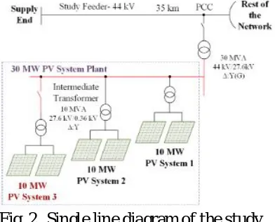
Fig. 2 shows a 44 kV feeder in a utility distribution network in Ontario, Canada
(name and location withheld for
confidentiality reasons) [16]. The study feeder system includes three 10 M W PV
systems with a total capacity of 30 M W connected about 35 km away from the utility transformer station (TS). The 30 M W PV plants are connected to the distribution system through a 30 M VA interface transformer, although each 10 M W PV system uses an intermediate transformer prior the interface transformer. Two solar systems with 10 M W generation are already connected to the PCC. Connection of the additional 10 M W PV system causes increased reverse power flow during light load conditions resulting in steady state over voltages. A 3.5 M var STATCOM is installed at PCC to mitigate steady state overvoltages.
The TOV is also observed to exceed the permissible limits during single line to ground faults (SLGF) or line to line ground (L-L-G) fault scenarios.
According to an Ontario utility requirement [29] the TOV caused by a DG facility should be less than 1.25 p.u. and in no circumstance exceed 1.30 p.u.
Fig. 2. Single line diagram of the study system
MODELING OF THE STUDY SYSTEM
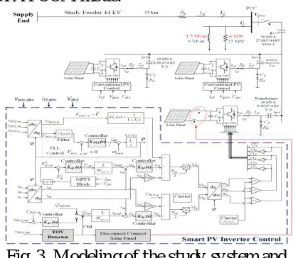
This section presents the modeling of different components of the study system in EMTDC/PSCAD software. The model of the study system is depicted in Fig. 3. The substation system is represented as an equivalent voltage source with 1.05 p.u. voltage to supply the 44 kV feeder. The 35 km line from substation to PCC is
Available online: http://edupediapublications.org/journals/index.php/IJR/ P a g e | 984
shunt admittance (e.g. line charging) is neglected. In Fig. 3, Rg and Lg represent the line resistance and inductance, respectively. The electrical load is considered to be a constant- power static RL load. At nominal voltage of 44 kVL-L, the total load is considered to be 30 M VA. The peak-time active and reactive loads are considered to be 27 M W and 6 M var, respectively, whereas during off-peak hours, these loads are 6 M W and 1.5 Mvar, respectively.
All three P V systems are utilized with 10 M VA two-level six-pulse IGBT-based voltage source inverters (VSI). The switching frequency is chosen to be 4 kHz to minimize the switching losses. For each PV system, an LCL filter is utilized to mitigate the harmonics caused by the switching frequency. The LCL filter consists of a series inductor (Lf), shunt capacitor (Cf) with series damping resistor (Rd) and another series inductor (Lt) corresponding to the transformer inductance. The combination of shunt capacitor in series with damping resistor is connected in delta configuration. The filter inductor is selected between 0.1 to 0.25 pu . The amount of reactive power generated by the filter capacitor also influences the reactive power compensation by the VSI. Hence, the filter capacitor value is designed to limit the reactive power exchange below 0.05 pu of the inverter power rate. To avoid resonance between filter capacitor and inductor, a damping resistor is added to filter capacitor in series.
CONTROLLER DESIGN
The other two PV systems use only conventional controllers to generate real power at unity power factor.
Fig. 3 illustrates the schematic of the smart PV inverter controller. The controller is designed in d-q frame and includes abc/dq transformation block, PLL, DC controller, current controllers, AC voltage controller, TOV detector unit and PWM unit. The PLL
unit extracts the phase angle of PCC voltage for transforming currents and voltages from abc-frame to dq-frame or vice versa [32]. The DC controller, in order to regulate DC link voltage at the reference value, generates the reference current for d-component of inverter current which represents the active current component. Consequently, the current controller in d-axis regulates the active current component to its reference value [32].
During daytime, the smart PV control operates as a conventional PV system i.e., in Full PV mode. If steady state voltage control is required in all three phases, together with real power generation, Partial STATCOM mode is activated. The Full STATCOM mode is activated when a temporary overvoltage TOV occurs due to unsymmetrical faults. M PPT based on incremental conductance method [30] is utilized during Full P V mode and Partial STATCOM mode. In Full- STATCOM mode, the M PPT mode is disabled and the real power generation is made zero by making the voltage across PV panel equal to its open circuit voltage. The entire inverter capacity is then utilized to absorb reactive power in order to reduce the phase voltage. After the TOV is mitigated, power production from the solar panels is enabled and control mode is switched to Partial STATCOM mode.
Available online: http://edupediapublications.org/journals/index.php/IJR/ P a g e | 985
The PCC voltage is controlled by the AC voltage controller. Therefore, either maximum reactive current or output of the AC voltage controller defines the reference value of reactive current control loop. The current controller in q-axis regulates the reactive current to its reference value. It is noted that the TOV Detector unit switches between voltage control mode and TOV mitigation mode. Also, this unit generates the command to enable or disable the power production from PV solar panels. The outputs of the controller are modulation indices in d-q frame, which are eventually converted to abc-frame using the phase angle of PCC voltage. The modulation indices in abc- frame are compared with carrier signal to generate gate pulses for the VSC switches [30], [32].
A. Operation M ode Selector
Fig. 4 shows the flowchart of the smart PV inverter control to select the operation mode. During daytime, the voltages in three phases are measured. If any phase voltage exceeds the TOV limit while the voltages in other phase/phases decrease substantially, the output of TOV Detector unit is trigged “ON”, and Full STATCOM mode is activated. The controller keeps the inverter current lagging the inverter voltage by 90 degrees (i.e. keeps absorbing reactive power) to reduce TOV until the phase voltages reach an acceptable value.
After the fault is cleared all the phase voltages will rise to their normal values. The controller thus recognizes that TOV is mitigated. It therefore enables power generation from the solar panels and switches to Partial STATCOM mode for steady- state voltage control. In partial STATCOM mode, the controller regulates the PCC voltage with Qrem, which is the inverter capacity remaining after real power generation.
During nighttime, the PV solar system operates in Full STATCOM mode to control either the steady-state voltage or TOV. The
smart PV inverter control thus
autonomously determines its operation mode and prioritizes between active power generation and reactive power exchange based on the system requirements, nature of transient/disturbance, time of the day and remaining inverter capacity.
B. Phase Locked Loop Control
The PCC voltage components in dq-frame are as:
Where V is the amplitude of PCC phase
voltage, ω0 is system frequency and θ is
the initial phase angle of the AC system.
Fig.4. Flowchart of the smart PV inverter operating mode
It should be noted that +− has a very small
value. Hence, it can be assumed that sin ( 0 0t ) +− . The open loop transfer function of
PLL with PI controller is:
Available online: http://edupediapublications.org/journals/index.php/IJR/ P a g e | 986 the PI controller with phase margin m 60 δ
= at cross over frequency ωc = 268 rad/s.
C. Current Control
The active and reactive power outputs of the inverter in dq- frame are [32]:
Due to PLL operation v= Vand viq = 0. Therefore, the real power output of the inverter is controlled by iid while reactive power output is controlled by iiq. However, the references values of the current controllers are received from outer loops based on control objectives and operation mode.
The inverter currents in dq-frame are [32], [34]:
where Vdc is the DC link voltage, M dq is modulation indices, Vpcc,dq are PCC voltages, ii,dq are inverter currents and Vi,dq are the voltages at AC side of the inverter in dq frame, respectively. By adding feed-forward terms to the control signals, (8) and (9) are transformed to linear and decoupled equations.
where ud and uq are input control signals. Other terms of (8) and (9) are added to control signals to obtain the modulation indices. M odulation indices are transformed to abc-frame and in the final stage are compared with carrier signal to generate the IGBT gate pulses. Although, the dynamic equations of current in d-q frame are stable, a PI controller is used to make the steady -state error zero and decrease the response time. To reduce the response time, the controller moves the transfer function pole
farther from origin of the real-imaginary coordinates [26].
D. DC Link Voltage Control
Due to losses in the switches of the inverter, the DC link of the inverter needs to absorb a slight amount of active power to maintain the DC voltage at the specific level. The required level of the DC voltage is determined by the AC side voltage of the inverter. When sun is available, the control utilizes a small amount of dc power from the solar panels to keep the capacitor charged, while the rest of the solar power is injected into the grid. During Full STATCOM mode or during nighttime, the inverter control absorbs a small amount of real power from the grid and charges the capacitor through inverter diodes. In Fig. 3, the power balance at DC side is as follows [34]:
where PPV P are P V panel power, DC-link capacitor power and DC side power of the VSC. By ignoring the VSC loss and filter losses, the DC side power of VSC can be considered equal to the power on the AC side. Hence,
Where Io is the diode saturation current, electron charge qe= − coulomb, T is the
cell temperature, k = 1.38 e -23 is the Boltzmann’s constant, while ns and np are the number of series and parallel cells. Due to non-linearity in the equation for solar power generation, the solar power is added as a feed- forward term to offset its effect [35]. The closed loop transfer function of d-component of invert current is given as:
Available online: http://edupediapublications.org/journals/index.php/IJR/ P a g e | 987
Fig. 5 demonstrates the block diagram of the DC link voltage control based on (17). The open loop transfer function of DC link voltage control with PI controller is:
where k dc, gain and z dc are the parameters of DC link voltage controller. Symmetrical Optimum technique [33] is used to design this controller with phase
margin δm =50o at cross over frequency ωc
= 364 rad/s.
E. PCC Voltage Control
In voltage control mode, the AC voltage controller defines the reactive current reference for current controller. However, in TOV reduction mode the reference value for reactive current controller is set to the maximum value as determined from the inverter kVA/M VA rating. This done to reduce the TOV in the most effective manner with largest possible inductive current. From Fig. 3, the PCC voltage is [32], [34]:
where ig,dq are d-q axis grid currents and Lg is grid inductance. It is noted that Vpcc−q is controlled at zero level by PLL
controller, and so, Vpcc−d represents the
PCC voltage. By neglecting the current of the shunt filter capacitor,
where, iL,dq are load current components in d-q frame. Therefore, the PCC voltage is expressed as:
The voltage control loop generates the reference for the reactive component of the inverter current control. The outer voltage control loop needs to be slower than inner current control loop. Fig. 6 shows the AC link voltage control based on (20). By using an Integral controller, the open loop transfer function of the PCC voltage is expressed as:
It should be noted that other terms of (22) are added as feed- forward terms.
F. TOV Detection Block
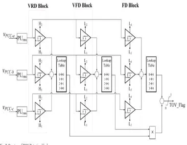
The TOV Detection block triggers the TOV flag when a temporary overvoltage occurs. When TOV flag is “ON”, the controller transforms the PV system into the Full STATCOM mode by changing the DC voltage to the open circuit voltage level of the solar panels thereby virtually disconnecting the solar panels. Reactive power is then absorbed using the full inverter capacity. When the fault is cleared and PCC voltage has reached acceptable value, the TOV flag is triggered “OFF” and the smart PV controller transforms into the Partial STATCOM mode for voltage control.
Available online: http://edupediapublications.org/journals/index.php/IJR/ P a g e | 988
low and high band limits of the hysteresis block for VRD unit are chosen as 1.20 pu and 1.25 pu, respectively. The VFD unit detects the fall in voltage. The output of VFD is triggered to “1” if one or two phase voltages pass the lower limit of the hysteresis band. The low and high bands of VFD unit are 0.8 pu and 0.85 pu respectively. When the output of both VRD and VFD blocks are “1” the TOV Detection block recognizes the TOV event and triggers the output to “1”. In other words, the TOV event is detected when one or two phase voltages are larger than 1.25 pu and voltages of other phase/phases are below 0.8 pu. After the fault is cleared all phase voltages will be above a certain value which is chosen as 0.85 pu.
Hence, FD unit triggers the TOV flag to become “0” when the fault is cleared. The Look Up Table in each case operates such that it provides a True “1” signal if the desired condition is met only in either one or two phases, but will give a False “0” output if the desired condition is met on all or none of the three phases. The hysteresis limits for different units are as below:
PSCAD/EMTDC SIM ULATION STUDIES
The performance of the smart PV inverter PV-STATCOM while fulfilling two control objectives, voltage control and TOV reduction, are presented in this section. The
PSCAD/EMTDC software is used for the simulation of the study system shown in Fig. 3. In all these studies, light (small) load is defined as 6 M W and 2 M var, whereas a heavy (large) load is considered to be 27 M W and 9 M var. Conventional PV System without Smart Inverter ControlIn this study, the incoming third 10 M W PV solar system does not have a smart PV inverter control. It operates as a conventional PV solar system with real power generation at unity power. Fig. 7 illustrates the PCC voltages in the three phases and their per-unit rms values
when PV systems generate.Before
Available online: http://edupediapublications.org/journals/index.php/IJR/ P a g e | 989
A. Smart PV Inverter PV-STATCOM
and Two Conventional PV systems
In this study, instead of using an external STATCOM, the incoming third PV system is equipped with the proposed smart PV inverter PV-STATCOM controller, while the other two PV systems operate as conventional P V systems.. Two different faults, single line-to-ground (SLG) fault and line-to-line-ground (LLG) fault, are considered to demonstrate the performance of the proposed controller.
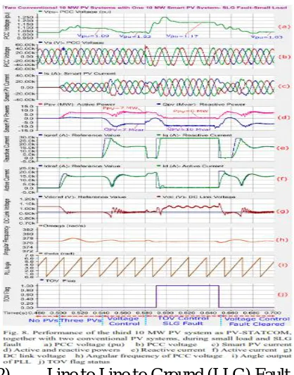
1) Single Line to Ground (SLG) Fault Fig. 8 (a)-(h) demonstrate the per-unit value of the PCC voltage (Vpcc,pu), the three-phase instantaneous PCC voltage (vpcc), smart PV system current (is), output powers (PPV, QPV), reactive current (Iq) active current (Id), DC link voltage (Vdc), angular frequency, PLL angle output and TOV flag status, respectively. t < 0.5sec: The smart PV system is not connected, and hence the real and reactive power of PV system are respectively, zero. t=0.5 sec: Three conventional PV system connected: Due to 21 M W active power generation of PV systems, the PCC voltage increases from 1.04 pu to 1.10 pu which is unacceptable. The reactive power is controlled at zero. t=0.54 sec: Partial STATCOM mode enabled: This operating mode for voltage control reduces the voltage to an acceptable range in less than one cycle utilizing the remaining capacity of the inverter. The reactive power output of the inverter reaches 7 M var capacitive from zero to maintain the voltage at acceptable range. However, the active power remains at same value since the reactive power control utilizes the remaining capacity of the inverter. The active and reactive currents follow their reference values to satisfy the voltage control objective.t=0.58 sec: SLG fault initiated: the SLG fault causes the voltage of phase “A” to fall to zero, whereas the other phase voltages experience TOV.
The proposed TOV detection unit detects this TOV event and triggers the TOV flag. Hence, the smart inverter autonomously switches from Partial STATCOM mode for voltage control to Full STATCOM mode for TOV reduction. In this situation, the controller changes the DC link voltage of the inverter to a value equal to the open circuit voltage of the solar panels (Fig. 8 (g)). It subsequently absorbs reactive power with full capacity of the inverter to reduce the voltages of phase “B” and phase “C”. On comparing with Fig. 8 (a), it is revealed that the proposed smart PV inverter control reduces the PCC voltage from 1.35 pu to 1.23 pu which is below the TOV limit specified in [29]. Fig. 8 (d) illustrates that active power output reaches zero and the entire capacity of the inverter is used for reactive power absorption. t=0.63 sec: SLG fault cleared: the fault is cleared and the controller returns to Partial STATCOM mode for voltage control while generating active power. The PCC voltage is controlled to an acceptable level (1.03 pu) by using the remaining capacity of the inverter.
Available online: http://edupediapublications.org/journals/index.php/IJR/ P a g e | 990
demonstrated in Fig. 9. As in the previous case of SLG fault, the smart PV inverter controls the PCC voltage to its reference value during steady-state.
t=0.58 sec: LLG fault initiated: the voltages of two phases phase “A” and phase “B” fall to zero and a TOV is caused in phase “C” due to LLG fault. The TOV detection unit triggers the TOV flag and the controller changes its mode from Partial STATCOM mode for voltage control to Full STATCOM mode for TOV reduction. This smart inverter control effectively reduces the TOV in the healthy phase to an acceptable value of 1.22 pu in about a cycle. It is noted that the designed PLL performs in a stable manner both during steady state and during SLG and LLG faults.
DISCUSSIONS
The proposed smart inverter
PV-STATCOM provides TOV mitigation using the full inverter capacity both during night and anytime during the day as needed by the grid. It provides steady state voltage control throughout the night. During daytime, it is assumed in this study that light load conditions do not arise during full noon hours i.e., when the solar system is producing its rated power. Hence there is some remaining inverter capacity available for steady state voltage regulation in Partial STATCOM mode. Under the revised IEEE Standard 1547 - 2018, the PV inverters are
also expected to provide reactive power injection and absorption capability of 44% and 25% of nameplate apparent power rating, respectively. This oversizing will further leave room for adequate steady state voltage control in the Partial P V-STATCOM mode. In the worst case, if light load conditions do arise due to a disturbance during noon hours, the solar farm can switch to Full PV-STATCOM mode for voltage control as long as the disturbance lasts. In other words, the proposed control offers the full functionality of a STATCOM for voltage control during day or night.
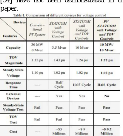
Table I shows the comparison between different systems. It is noted that the PV-STATCOM control proposed in which was meant to provide only steady state voltage control is unable to mitigate the TOV issue. It is only with the TOV control strategy proposed in this paper, the PV solar farm as
PV-STATCOM can suppress TOV
effectively. In Table I, the acceptable steady state voltage range is between 0.94 pu and 1.05 pu whereas the TOV limit is 1.25 pu [29]. Due to the lack of space, the results of STATCOM with and without TOV control [34] have not been demonstrated in this paper.
Available online: http://edupediapublications.org/journals/index.php/IJR/ P a g e | 991
50-100 times cheaper than an equivalent STATCOM for accomplishing the same voltage control functions. This is because only the additional P V- STATCOM control with its associated control and measurement circuitry, and protection needs to be installed on the existing inverters of the PV solar farm. The entire existing electrical (and civil) substation infrastructure of the PV solar farm including the transformers, bus-work, circuit breakers, lines and cables, etc. is utilized for implementing the overall
PV-STATCOM . If a new SVC or
STATCOM needs to be commissioned, the complete substation needs to be built all over, and new inverter needs to be procured. These costs are clearly avoided with PV-STATCOM.
This paper considers a single equivalent inverter for an entire PV solar farm to demonstrate a new control concept, whereas an actual solar farm may have multiple inverters involving plant controls and communication delays, etc. In such a situation, some PV inverters being utilized as PV-STATCOMs may need to bypass the plant controls and respond rapidly to TOVs in the grid. Such controls are being developed and will be reported in a future paper.
CONCLUS IONS
This paper presents an innovative smart PV inverter control as STATCOM , named PV-STATCOM, for controlling the steady state overvoltage and more importantly, mitigation of Temporary Overvoltages (TOV). This novel control in Partial STATCOM mode regulates the steady state over voltage to the desired reference value within one and half cycle. Further, this smart inverter control in Full STATCOM mode successfully reduces the TOV caused during both single line to ground fault and line to line to ground fault to within utility acceptable values within one cycle.
For the studied actual distribution system the proposed PV- STATCOM control can help integrate the third 10 M W PV solar farm thereby eliminating the need for the actually installed STATCOM for the same purpose. The proposed PV- STATCOM control is expected to be at least 50 times cheaper than a conventional STATCOM . This control can therefore bring a significant saving for the concerned utility. Such a control can also help in increas ing the hosting capacity of PV solar farms on distribution systems which may be restricted due to voltage issues. This control can potentially open a new revenue making opportunity for the solar farms for providing the STATCOM service.
REFERENCES
[1] F. Katiraei and J. R. Aguero, "Solar PV Integration Challenges," in IEEE Power and Energy M agazine, vol. 9, no. 3, pp. 62-71, M ay-June 2011.
[2] Obi, M anasseh, and Robert Bass. "Trends and challenges of grid - connected photovoltaic systems–A review." Renewable and Sustainable Energy Reviews 58 (2016): 1082-1094. [3] D. Cheng, B. A. M ather, R. Seguin, J.
Hambrick, and R. P. Broadwater, "Photovoltaic (PV) impact assessment for very high penetration levels," IEEE Journal of Photovoltaics, vol. 6, pp. 295-300, 2016.
[4] “High-Penetration PV Integration Handbook for Distribution Engineers”,
Technical Report
NREL/TP-5D00-63114 January 2016
[5] R. J. Bravo, R. Salas, T. Bialek, and C. Sun, "Distributed energy resources challenges for utilities," Proc. 2015 IEEE 42nd Photovoltaic Specialist Conference, P VSC 2015, 2015.
[6] Jeff Smith and M att Rylander, “PV Hosting Capcity on Distribution
Available online: http://edupediapublications.org/journals/index.php/IJR/ P a g e | 992
[7] SJ Steffel, PR Caroselli, AM Dinkel, JQ Liu, RN Sackey, and NR Vadhar, "Integrating solar generation on the electric distribution grid," IEEE Transactions on Smart Grid,, vol. 3, pp. 878-886, 2012
[8] Y. Kabasawa, T. Noda, K. Fukushima and K. Nemoto, "Consumer voltage regulation using coordinated control of
distributed static synchronous
compensators - STATCOMs," in Proc. 2012 3rd IEEE PES Innovative Smart Grid Technologies Europe, pp. 1-7. [9] N. G. Hingorani and L. Gyugyi,
Understanding FACTS, New York: IEEE-Wiley, 1999.
[10] “System Impact Assessment Report – Grand Renewable Energy Park Project”
Independent Electricity System
Operator (IESO) Report No. CAA ID 2010-399, M ay 2011
[11] D. Iioka, K. Sakakibara, Y. Yokomizu, T. M atsumura and N. Izuhara, "Distribution voltage rise at dens e photovoltaic generation area and its suppression by SVC," Electrical Engineering in Japan, vol. 166, no.2, pp. 47-53, 2009.
[12] G. E. M. Aly, A. Zeftawy, A. El-Hefanwy and S. A. Eraky, "Reactive power control on residential utility-interactive PV power systems," Electr. Power Syst. Res., vol. 51, no. 3, pp. 187-199, 1999.
[13] N. K. Roy, H. R. Pota, A. M ahmud and M . J. Hossain, "D-STATCOM control in distribution networks with composite loads to ensure grid code compatible performance of photovoltaic generators," in Proc. 2013 IEEE 8th Conf. on Industrial Electronics and Applications, pp. 55-60.
[14] https://library.e.abb.com/public/9ae 411b 2ed304cbba37115159e81fb5d/9
AAK10103A2230_PV-Cluster_STATCOM -CS-LR.pdf
[15] http://www.abb.pl/cawp/seitp202/c3 a70ee0924b6062c12580ec00529aa0
.aspx
[16] L. Tang, A. Yan, A. Narang, M . Ali, and L. M arti, “M itigation for Connecting Distributed Generators beyond Power Distance Limitation”, paper 436, Proc. 2014 CIGRE Canada Conference, Toronto, Sep. 2014.
[17] Yi Zhang, C. M ensah-Bonsu, P. Walke, S. Arora and J. Pierce, "Transient over-voltages in high voltage grid-connected PV solar interconnection", in Proc. 2010 IEEE Power & Energy Society General M eeting, pp. 1-6.
[18] J. W. Smith, W. Sunderman, R. Dugan and B. Seal, “Smart inverter volt/var control functions for high penetration of PV on distribution systems,” in Proc. IEEE PSCE, 2011, pp. 1-6.
[19] “Common Functions for Smart Inverters, Version 3”, EPRI Palo Alto, CA, Report No. 3002002233, Feb. 2014 [20] B. M ather, “NREL/SCE
High-Penetration PV Integration Project: Report on Field Demonstration of Advanced Inverter Functionality in
Fontana, CA”, NREL Report
NREL/TP-5D00-62483, 2014.
[21] M . M orjaria, D. Anichkov, V. Chadliev, and S. Soni, “A Grid-Friendly Plant”, IEEE Power and Energy M agazine, M ay-June 2014, pp. 87-95
[22] IEEE 1547-2018, IEEE Standard for Interconnecting Distributed
Resources with Electric Power
Systems, IEEE Standards Association, 2018
[23] R. K. Varma, V. Khadkikar, and R. Seethapathy, “Nighttime application of PV solar farm as STATCOM to regulate grid voltage,” IEEE Trans. Energy Conversion (Letters), vol. 24-4, pp. 983–985, 2009
[24] Rajiv K. Varma, V. Khadkikar and S. A. Rahman, “Utilization of Distributed Generator Inverters as STATCOM ”
Available online: http://edupediapublications.org/journals/index.php/IJR/ P a g e | 993
PCT/CA2010/001419 filed on 15
September, 2010.
[25] R. K. Varma, S. A. Rahman, M . A.C., R. Seethapathy and T. Vanderheide, “'Novel Nighttime Application of P V Solar Farms as STATCOM (PV- STATCOM)'”, Proc. IEEE PES GM , 2012
[26] R. K. Varma, S. A. Rahman, and T. Vanderheide, "Novel Control of P V Solar Farm as STATCOM (PV-STATCOM) for Enhancing Grid Power Transmission Limits During Night and Day", IEEE Trans. on Power Delivery, Vol. 30, No. 2, pp 755-763, April 2015 [27] Rajiv K. Varma and Ehsan Siavashi,
“PV-STATCOM – A New Smart Inverter for Voltage Control in
Distribution Systems”, IEEE
Transactions on Sustainable Energy, IEEE Xplore Early Access, Digital
Object Identifier:
10.1109/TSTE.2018.2808601
[28] R. K. Varma, "M ultivariable M odulator Controller for Power Generation
Facility", PCT Application
(PCT/CA2014/051174) filed Dec. 6, 2014
[29] Hydro One Inc. (2013). Distributed Generation Technical Interconnection Requirements- Interconnections at Voltages 50kV and Below (Rev. 3 ed.) [30] A. Yazdani, A. R. Di Fazio, H.
Ghoddami, et al., “M odeling guidelines and a benchmark for power system simulation studies of three-phase single-stage photovoltaic systems,” IEEE Transactions Power Delivery, vol. 26, no. 2, pp. 1247–1264, 2011. [31] M . Liserre, F. Blaabjerg, and S.
Hansen, “Design and control of an LCL- filter-based three-phase active rectifier,” Industry Applications, IEEE Transactions on, vol. 41, no. 5, pp. 1281–1291, 2005.
[32] A. Yazdani and R. Iravani, Voltage-sourced converters in power systems:
modeling, control, and applications. John Wiley & Sons, 2010.
[33] W. Leonhard, Control of Electrical Drives. Springer Science & Business M edia, 2001.
[34] E. M . Siavashi, “Smart PV inverter control for distribution systems,” in Electronic Thesis and Dissertation Repository. 3065. https://ir.lib.uwo. ca/ d/3065, 2015.