ABSTRACT
DURHAM III, JOHN WILLIAM. Preparation and Characterization of Bioactive Coatings on Polymeric Implants. (Under the direction of Afsaneh Rabiei).
Polymeric materials such as polyether ether ketone (PEEK) are well suited for orthopedic and dental medical implants due to their mechanical stiffness matching with human bone and dentin. Their chemical stability and heat resistance also make them compatible with various sterilization techniques. However, the hydrophobic surface of PEEK implants induces fibrous encapsulation, which is unfavorable for stable implant anchorage. The application of bioactive coatings has shown promise for addressing this issue, though drawbacks exist in terms of substrate damage due to high processing temperatures, lack of coating adhesion and uniformity.
HA layer; crystalline HA exhibits lower dissolution rates in vitro and in vivo compared to amorphous HA. The coatings were heat treated by unconventional methods to address the incompatibility of PEEK with conventional HA sintering temperatures. These included variable frequency microwave processing, hydrothermal processing by autoclave, and a combined approach to assess their effectiveness in crystallizing the HA and increasing its bioactivity.
These coatings were first applied to the cross section of flat, smooth PEEK discs and analyzed by scanning electron microscopy (SEM), X-ray diffraction (XRD), Fourier transform infrared spectroscopy (FTIR), and adhesion strength testing. Appropriate heat treatment fixtures were designed and manufactured and processing parameters were optimized for crystallinity and bond strength. Representative samples for each treatment were then subjected to a cell culture study to determine the in vitro biological response. The results showed that the microwave and autoclave heat treatment methods were capable of crystallizing HA, and that microwave treated coatings retained higher adhesion strength. The biological response of precursor bone forming cells showed that heat-treated coatings encouraged faster osteoblast
differentiation and more bone growth on the sample surface compared to as-deposited coatings and uncoated PEEK.
Preparation and Characterization of Bioactive Coatings on Polymeric Implants
by
John William Durham III
A dissertation submitted to the Graduate Faculty of North Carolina State University
in partial fulfillment of the requirements for the degree of
Doctor of Philosophy
Mechanical Engineering
Raleigh, North Carolina 2015
APPROVED BY:
___________________________________________ ___________________________________________
Dr. Afsaneh Rabiei Dr. Andrew DiMeo
Chair of Advisory Committee
DEDICATION
BIOGRAPHY
ACKNOWLEDGMENTS
I would first like to acknowledge my advisor, Dr. Afsaneh Rabiei, for introducing this exciting research project to me and convincing me to continue my education at NC State. I cannot express how grateful I am for all the support and effort that she has put forth on my behalf, and for the wide array of unique, multidisciplinary opportunities I have been presented with during the course of this research. Through this project, I was able to participate in critical aspects of equipment design and acquisition, experimental optimization, materials testing/analysis, microbiological and clinical protocols, and process scalability. The experience I have gained working on this research with Dr. Rabiei has truly advanced my knowledge of material design and implementation and has cultivated and refined my career goals.
I would like to thank Dr. Gracious Ngaile and Dr. Larry Silverberg for their time and participation as key members of my advisory committee in addition to their support in the completion of this work. Thanks also to Dr. Andrew DiMeo for offering his advice and support regarding the biomedical and product market aspects of this project.
I would like to acknowledge the NCSU Nanofabrication Facility (NNF) and the Analytical Instrumentation Facility (AIF) for the training and access to critical material processing and analysis equipment. In particular, thanks to Marcio Cerullo, Henry Taylor, Nicole Hedges, and Bruce Sprague from NNF, and Chuck Mooney and Roberto Garcia from AIF for all their effort and support.
Thank you to our collaborators on this project: Matthew J. Allen, MA, Vet MB, PhD from the Department of Veterinary Medicine at the University of Cambridge, United Kingdom, and Dr. Joo L. Ong, Dr. Teja Guda, and Sergio Montelongo from the Department of Biomedical Engineering at the University of Texas at San Antonio.
A special thanks to my colleagues in Dr. Rabiei’s research group, the Advanced Materials Research Laboratory (AMRL): former students Dr. Stefan Sandukas, Dr. Matias Garcia-Avila, Dr. Shuo Chen, and current group member Jacob Marx for their support and friendship over the past few years. I would also like to acknowledge Steve Cameron for his support, time and the machining and fabrication efforts put forth to help with this project in the Mechanical and Aerospace Engineering Machine Shop.
TABLE OF CONTENTS
LIST OF TABLES ... ix
LIST OF FIGURES ... x
CHAPTER 1: INTRODUCTION ... 1
1.1. Biomedical implants ... 1
1.2. Biomaterials for orthopedic and dental implants ... 2
1.2.1. Metals ... 3
1.2.2. Ceramics ... 7
1.2.3. Polymers ... 8
1.3. PEEK implants ... 10
1.4. Biocompatibility and osseointegration ... 15
1.5. Bioactive coatings ... 20
1.5.1. Biologically derived coatings ... 20
1.5.2. Calcium phosphate coatings ... 22
1.6. Ion beam assisted deposition ... 26
1.7. Two-layer bioactive coating on PEEK ... 30
1.8. Crystallization of HA on PEEK ... 31
1.8.1. Microwave processing ... 31
1.8.2. Autoclave Processing ... 34
1.9. IBAD deposition of bioactive coatings on PEEK ... 34
CHAPTER 2: LITERATURE REVIEW ... 38
2.1. Surface modification of PEEK ... 38
2.1.1. Physical surface modification ... 39
2.1.2. Chemical surface modification ... 44
2.1.3. Challenges and outlook ... 47
2.2. PEEK composites ... 48
2.2.1. Processing methods ... 48
2.2.2. Properties of PEEK composites ... 51
2.2.3. Challenges and outlook ... 62
2.3. Bioactive coatings on PEEK ... 62
2.3.1. Titanium coatings ... 63
2.3.2. Titanium oxide coatings ... 66
2.3.3. Hydroxyapatite coatings ... 69
2.4. Crystallization of hydroxyapatite films ... 80
2.4.1. Laser annealing ... 80
2.4.2. Hydrothermal treatment ... 81
2.4.3. Microwave heating ... 83
CHAPTER 3: DEPOSITION, HEAT TREATMENT AND CHARACTERIZATION OF HA/YSZ COATINGS ON PEEK ... 88
3.1.1. Substrate preparation ... 89
3.1.2. Surface activation ... 91
3.1.3. Coating deposition ... 92
3.1.4. Post-deposition heat treatment ... 98
Figure 3-12. Steris sterilizer autoclave unit ... 100
3.1.5. X-ray diffraction ... 101
3.1.6. Scanning electron microscopy ... 101
3.1.7. Fourier transform infrared spectroscopy ... 102
3.2. Results ... 103
3.2.1. Microstructural analysis ... 103
3.2.2. Compositional analysis ... 105
3.2.3. Fourier transform infrared spectroscopy ... 106
3.3. Discussion of coating characterization ... 108
3.4. Summary of IBAD deposition on PEEK ... 109
CHAPTER 4: IN VITRO RESPONSE OF BIOACTIVE COATINGS ON PEEK ... 110
4.1. Materials and methods ... 112
4.1.1. Cell culture sample preparation ... 112
4.1.2. Cell growth and seeding conducted at OSU by M.J. Allen ... 114
4.1.3. Cell proliferation analysis conducted at OSU by M.J. Allen ... 114
4.1.4. Measurement of total DNA content conducted at OSU by M.J. Allen ... 115
4.1.5. Osteoblastic differentiation analysis conducted at OSU by M.J. Allen ... 115
4.1.6. Osteoblastic mineralization analysis conducted at OSU by M.J. Allen ... 115
4.1.7. Statistical analysis conducted at OSU by M.J. Allen ... 116
4.2. Results ... 117
4.2.1. Cell proliferation and migration ... 117
4.2.2. Cell differentiation ... 119
4.2.3. Mineralization of new bone deposits ... 121
4.3. Discussion of in vitro results ... 123
4.4. Summary of cell culture tests ... 125
CHAPTER 5: PREPARATION AND ANALYSIS OF HA/YSZ COATINGS ON CYLINDRICAL PEEK ... 126
5.1. Materials and methods ... 127
5.1.1. Cylindrical PEEK substrate preparation ... 127
5.1.2. Surface activation ... 128
5.1.3. IBAD deposition on cylindrical PEEK ... 129
5.1.4. Post-deposition heat treatment of cylindrical PEEK ... 132
5.1.5. Coating uniformity ... 133
5.1.6. Coating adhesion strength ... 133
5.1.7. Microstructure and chemical analysis ... 136
5.2. Results ... 139
5.2.1. Coating uniformity ... 139
5.2.2. Coating adhesion ... 140
5.2.3. Microstructural analysis and crystallinity ... 143
5.4. Summary of coatings on cylindrical PEEK ... 153
CHAPTER 6: HA/YSZ COATINGS ON CYLINDRICAL PEEK IMPLANTS: BIOMECHANICAL AND HISTOLOGICAL STUDY IN A RABBIT MODEL ... 154
6.1. Materials and methods ... 155
6.1.1. PEEK implants ... 155
6.1.2. Surgical procedure conducted at Powered Research by M.J. Allen ... 156
6.1.3. Micro-CT characterization conducted at UTSA by J.L. Ong, et al. ... 158
6.1.4. Histomorphometric evaluation conducted at UTSA by J.L. Ong, et al. ... 159
6.1.5. Biomechanical Push-out test conducted at UTSA by J.L. Ong, et al. ... 160
6.1.6. Statistical Analysis conducted at UTSA by J.L. Ong, et al. ... 161
6.2. Results ... 162
6.2.1. Micro-CT characterization ... 162
6.2.2. Histomorphometric evaluation ... 166
6.2.3. Biomechanical push-out testing ... 172
6.3. Discussion of in vivo results ... 174
6.4. Summary of animal study ... 177
CHAPTER 7: CONCLUSIONS ... 178
CHAPTER 8: RECOMMENDATIONS FOR FUTURE STUDIES ... 182
LIST OF TABLES
CHAPTER 1
Table 1-1: Mechanical properties of biological tissues [16] ... 9 Table 1-2: Mechanical properties of typical biomaterials [16] ... 9 CHAPTER 2
Table 2-1. Agglomeration in nano-scale HA-PEEK composites [98] ... 59 Table 2-2. Approximate adhesion strength of various HA coating techniques
measured by pull-off tests [131] ... 79 CHAPTER 5
LIST OF FIGURES
CHAPTER 1
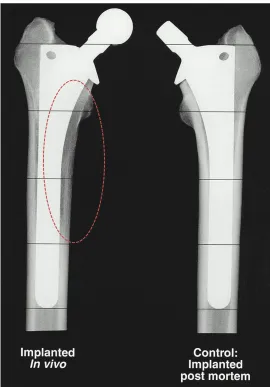
Figure 1-1. Stress shielding. The effects of stress shielding on perimplant bone tissue of a hip stem after typical biomechanical loading (left) and without loading (right). Darker regions surrounding the implant in the loaded implant are indicative of stress-shielding [10]. Circled area identifies stress shielded region. ... 5 Figure 1-2. Chemical structure of PEEK [18] ... 11 Figure 1-3. Radiography of PEEK. PEEK tailored for optimal contrast vs. metallic
implants for spinal fusion cages [19] ... 12 Figure 1-4. Vertebra anatomy. Top view of fifth lumbar vertebra showing both
cancellous (porous) and cortical (dense) bone tissues [23] ... 13 Figure 1-5. Lumbar disc disectomy. Removal of the L5-S1 intervertebral disc via
anterior approach [24] ... 14 Figure 1-6. PEEK spinal cage. Location of PEEK implant insertion for lumbar
interbody fusion procedure [15]. Circled area indicating PEEK fusion cage. . 15 Figure 1-7. Cell-surface interactions. Normal biological response to a surface after
implantation [26] ... 16 Figure 1-8. The organic and inorganic material composition of bone [27] ... 18 Figure 1-9. Ion beam assisted deposition schematic. Argon ions (red) sputter
target atoms (blue) to the substrate surface to form the coating; secondary ions impart additional energy at the substrate surface ... 28 Figure 1-10. Functionally-graded HA coating. Cross-sectional TEM image of the
FGHA coating on a Si substrate showing the gradient in HA crystallinity
through the thickness [53] ... 29 Figure 1-11. HA/YSZ coating prepared by RF sputtering. As-deposited amorphous
HA coating (a-b), autoclave processed (c-d), and microwave processed (e-f) [49] ... 33 CHAPTER 2
Figure 2-1. Cell proliferation after plasma treatment. NH3/Ar plasma treated
PEEK surface (triangle) compared to TCPS (circle) [65] ... 40 Figure 2-2. Osteosarcoma cell proliferation and spreading on untreated PEEK
(left) vs. CH4/O2 plasma treated PEEK (right) [66] ... 41 Figure 2-3. AFM surface observation and contact angle. Surface of untreated PEEK (a,c) and treated PEEK (b,d) [67] ... 43 Figure 2-4. SPEEK surface treatment modification. SEM observation of
Figure 2-5. Bone volume around SPEEK. Results of bone volume after
implantation in vivo comparing PEEK with sulfonated PEEK surfaces [70]. .. 47 Figure 2-6. Process of injection molding [73] ... 49 Figure 2-7. Process of compression molding [73] ... 50 Figure 2-8. Mechanical analysis of HA-PEEK composite [85] ... 53 Figure 2-9. Debonding of HA particles from PEEK matrix in 20 vol.% HA-PEEK
composite [85]. Black arrow indicates HA particles; white arrow shows particle-matrix debonding. ... 54 Figure 2-10. Mechanical characterization of HA-PEEK composites prepared by in
situ synthesis [77] ... 56 Figure 2-11. Mechanical properties of nano-scale HA-PEEK composites [92] ... 57 Figure 2-12. TEM observation of 15 vol.% nano-scale HA-PEEK composite sample
showing agglomeration of nanoparticles [98] ... 59 Figure 2-13. SEM observation of nano-scale HA-PEEK composite (6.1 vol.%)
processed via in situ synthesis [99] ... 61 Figure 2-14. Mechanical properties of nano-scale HA-PEEK composites processed
by in situ synthesis [99] ... 61 Figure 2-15. EBD Ti-coated PEEK surface (left) and cross-section (right) [105] ... 65 Figure 2-16. TiO2 coating on PEEK via AIP deposition [110] ... 67
Figure 2-17. Nanoporous TiO2 coating on PEEK loaded with BMP-2 growth factor
showing surface morphology (left) and cross sectional microstructure (right) [112] ... 69 Figure 2-18. SEM of uncoated PEEK surface (left) compared to HA-coated surface
prepared by cold spraying [45] ... 72 Figure 2-19. SEM of aerosol-deposited HA particle coating on PEEK [47] ... 73 Figure 2-20. SEM observation of nano-scale HA particle coating on PEEK via spin
coating (left) and chemical deposition (right) [117,119] ... 75 Figure 2-21. SEM image of dense amorphous HA film prepared by PLD technique
[124] ... 76 Figure 2-22. SEM observation of the RF-sputtered HA coatings as deposited (left)
and after heat treatment (right) showing transition from amorphous to crystalline HA structure [125] ... 78 Figure 2-23. SEM observation of sputtered amorphous HA coating prepared on
polyethylene as deposited (left) and after crystallization by laser annealing (right) [139] ... 81 Figure 2-24. SEM observation of hydrothermal crystal nucleation and growth of
sputtered HA films at 6 hours (left) and 12 hours (right) [141] ... 82 Figure 2-25. Microwave annealing profile of HA film [143] ... 84 CHAPTER 3
Figure 3-3. Plasma barrel reactor at NNF cleanroom used to clean PEEK
substrates before coating deposition ... 92 Figure 3-4. IBAD deposition system located in the cleanroom at the NCSU
nanofabrication facility (NNF) ... 93 Figure 3-5. Interior of the IBAD chamber and its main components ... 93 Figure 3-6. Planar substrate holder for PEEK samples (pictured), with silicon chip used for coating thickness measurements ... 94 Figure 3-7. IBAD film uniformity in the x direction; 0-position represents the
center of the 152-mm diameter silicon wafer ... 95 Figure 3-8. IBAD film uniformity in the y direction; 0-position at center of wafer
... 96 Figure 3-9. Ion current density profile of the 16-cm primary ion source beam
(from KDC 16cm ion source manual) ... 96 Figure 3-10. IBAD film growth curve for YSZ on silicon, measured by profilometry
... 98 Figure 3-11. Variable frequency microwave oven at AMRL ... 99 Figure 3-12. Steris sterilizer autoclave unit ... 100 Figure 3-13. SEM images of the cross-sections of AD (a), AD+AC (b), and MW+AC
(c) coatings. Inscribed boxes show location of magnified view of HA layer (right side) ... 104 Figure 3-14. XRD data of HA target and HA/YSZ coatings as-deposited (AD),
autoclave treated (AD+AC), and microwave plus autoclave treated (MW+AC). Standard peak locations are indicated for YSZ and HA phases ... 106 Figure 3-15. FTIR spectra of HA target and HA/YSZ coatings as-deposited (AD),
autoclave treated (AD+AC), and microwave plus autoclave treated (MW+AC) ... 107 CHAPTER 4
Figure 4-1. MC3T3 cells seeded on a sample surface; Green stain (actin) showing cell spreading, blue stain (cell nucleus) indicating cell vitality, red stain (integrin) showing cell anchoring locations ... 111 Figure 4-2. Test sample groups used for cell-culture study from left to right:
uncoated PEEK, AD, AD+AC, MW+AC ... 113 Figure 4-3. MTT assay results at various time points for uncoated PEEK (PEEK),
as-deposited (AD), autoclave treated (AD+AC), and microwave plus autoclave treated (MW+AC). Statistically similar groups indicated by group (a, b, etc.) ... 118 Figure 4-4. DNA content results at various time points for uncoated PEEK (PEEK),
Figure 4-5. Normalized osteocalcin results at various time points for uncoated PEEK (PEEK), as-deposited (AD), autoclave treated (AD+AC), and microwave plus autoclave treated (MW+AC). Statistically similar groups indicated by group (a, b, etc.) ... 121 Figure 4-6. Biomineralization results shown by Alizarin Red-S content for
uncoated PEEK (PEEK), as-deposited (AD), autoclave treated (AD+AC), and microwave plus autoclave treated (MW+AC). Statistically similar groups indicated by group (a, b, etc.) ... 122 CHAPTER 5
Figure 5-1. Image of cylindrical PEEK substrates ... 128 Figure 5-2. Substrate holder schematic for IBAD deposition of HA/YSZ coatings on cylindrical PEEK rods ... 130 Figure 5-3. PEEK sample mounting schematic for use with IBAD substrate holder
... 131 Figure 5-4. IBAD deposition schematic for cylindrical PEEK substrates ... 132 Figure 5-5. Image of pull-off adhesion strength testing machine in AMRL; white
box indicates sample mounting location ... 135 Figure 5-6. Pull-off test schematic showing determination of adhesion strength
from max load and stud area ... 136 Figure 5-7. SEM image showing FIB sample thinning in preparation for TEM
imaging ... 138 Figure 5-8. a) Optical image of the cross-section of cylindrical PEEK sample; b-e)
zoomed in SEM images of the cross section of the YSZ/HA coating at various locations around the PEEK implant circumference. ... 140 Figure 5-9. Adhesion strength test site showing failure modes of single layer
coated PEEK substrates. Optical microscope images of rough machined surfaces (left) and smooth prepared surfaces (right). Black arrows indicate machining marks (right) and polishing marks (right); white arrow shows cohesive epoxy failure ... 142 Figure 5-10. Adhesion strength of HA/YSZ coatings prepared by IBAD on smooth
PEEK surfaces ... 143 Figure 5-11. TEM observation of the as-deposited HA/YSZ coating (a), layer
interface (b), and SAD patterns of HA (c) and YSZ (d) layers ... 144 Figure 5-12. TEM observation of the microwave-annealed HA/YSZ coating (a),
layer interface (b) showing crystalline structures. HRTEM image (c) and FFT pattern (inset) of crystalline HA region ... 145 Figure 5-13. TEM observation of the microwave plus autoclave treated HA/YSZ
coating on PEEK (a), with and SAD pattern of the HA layer (b) ... 146 Figure 5-14. HRTEM observation of the microwave plus autoclave treated coating
crystalline (c-HA ) regions (b). HA grain boundary (dashed line) within
crystalline region (c), and atomic mixing at the HA/YSZ interface (e) ... 147 Figure 5-15. EDS sample region imaged by STEM (left), and resulting Ca and P EDS signals from the corresponding boxed area (right) ... 148 Figure 5-16. Calcium to phosphate ratio of as-deposited (AD), microwave
annealed (MW), and microwave plus autoclave (MW+AC) coating samples149 CHAPTER 6
Figure 6-1. Size and surface finish of PEEK implants (A). Surgical site with implant inserted (B) and x-ray visualization of placement location--—arrows indicate the defect boundaries within which the implant is located (C-D) ... 158 Figure 6-2. MicroCT analysis of bone regeneration within specimens at 6 weeks
(top) and 18 weeks (bottom) showing new bone growth around the implant surface for each of the sample groups; white arrows indicate bone growth within the central implant canal observed with the coated samples ... 163 Figure 6-3. Three-dimensional representations of the PEEK, AD+MW and
AD+MW+AC implants (pseudo color blue) placed in the rabbit femoral condyles (bone pseudo colored yellow) after 6 weeks and 18 weeks of
implantation ... 164 Figure 6-4. Micro-CT Quantification. (A) Bone volume regenerated on the implant
surface itself was significantly higher in the AD+MW+AC coated implants compared to the PEEK implants after 18 weeks. The bone volume
regenerated on the AD+MW+AC implants increased significantly from 6 to 18 weeks. (B) The mineral density of the regenerated bone in the surrounding envelope did show a significant increase for all three implant types between 6 and 18 weeks implantation. (* indicates significant difference between groups at p<0.05) ... 165 Figure 6-5. Histological evaluation – short term. Bone growth against the PEEK
implants (A) as well as the AD+MW (C) and AD+MW+AC (E) coated implants at 6 weeks. The tissue sections stained with paragon and counter-stained with Analine Blue show the ossified tissue blue and the fibrous tissue pink. The implant is seen as black in the slides. Mineralized tissue was seen to be highly cellular at 6 weeks (B,D,F). Scale bar 10 mm (A,C,E); 300 µm (B,D,F). ... 168 Figure 6-6. Histological evaluation – long term. Bone growth against the PEEK
implants (A) as well as the AD+MW (C) and AD+MW+AC (E) coated implants at 18 weeks. The trabeculae of bone in contact with the implant surface
appeared to thin out in the PEEK group at 18 weeks (B) compared to the bone fronts in contact with the AD+MW (D) and AD+MW+AC (F) coated implants at the same time. Scale bar 10 mm (A,C,E); 300 µm (B,D,F). ... 169 Figure 6-7. Bone apposition rate – short term. Calcein green staining was
to stain instantaneous mineralization fronts in remodeling bone. The difference between the two fronts was then used to quantify the bone mineral apposition rate near the implant surface for the AD+MW (C, D) and AD+MW+AC (E, F) coated implants compared to the PEEK (A, B) implants. 170 Figure 6-8. Bone apposition rate – long term. Calcein green staining was
administered 7 days and 1 day prior to euthanasia of the animals at 18 weeks. The distance between the mineralization fronts was used to quantify the apposition rate near the implant surface for the AD+MW (C, D) and
AD+MW+AC (E, F) coated implants compared to the PEEK (A, B) implants. 171 Figure 6-9. Histological quantification. (A) The percentage of implant perimeter
in contact with mineralized tissue was found to range between 20 and 80% across the groups analyzed. The AD+MW group showed a trend of higher bone to implant contact than the PEEK and AD+MW+AC after 6 weeks and both the AD+MW and AD+MW+AC coated implants showed a trend of greater bone to implant contact than the PEEK group after 18 weeks. (B) No
significant differences were found between the bone apposition rates on the surfaces of the three different implants after 6 or 18 weeks implantation. A general trend of reduced bone apposition rate was observed across groups at 18 weeks compared to 6 weeks. ... 172 Figure 6-10. Biomechanical push-out strength. (A) In terms of the interfacial
CHAPTER 1: INTRODUCTION
1.1. Biomedical implants
Surgical treatment options involving implantable devices are intended to restore normal biologic functions to a patient suffering from acute or chronic conditions that directly affect their quality of life. In general, the goal is to replace a non-functional biological component with a prosthetic equivalent. It follows that these implants are designed to mimic and facilitate the operations of the tissue they replace, an important consideration for device development. There are various types of biomedical implant devices on the market today, ranging from fixation rods for broken bones to synthetic heart valves.
and 64% of those over 65 according to the 2009 and 2010 National Health and Nutrition Examination Survey [3]. Lower back pain (LBP) is even more concerning at 80% lifetime prevalence. It is often caused by lumbar degenerative disc disease (LDDD) and is responsible for $100 to $200 billion annually due to lost productivity and
procedural costs [4,5]. In fact, spinal fusion to treat LBP is among the most frequently performed procedures in operating rooms in U.S. hospitals [1].
Proper material selection for implantable devices is critical for effective
treatment of these degenerative conditions. The implant material affects the short-term success of the procedure as well as the lifetime of the implant in vivo. It should be able to support the necessary mechanical load and sustain biological activity. In cases where the implant ceases to perform as intended, costly and painful revision procedures are often needed to restore the patient’s quality of life [6]. In the short term, this can be caused by infection and depends heavily on procedural protocols. Long term causes of device failure are: i) inflammatory immune response and ii) device loosening [7]. Ever-increasing annual procedural numbers and the emergence of a substantial youth patient population has made extending implant lifetime a driving factor for the development of biomaterials [8].
1.2. Biomaterials for orthopedic and dental implants
Orthopedic and dental implant devices are designed to treat traumas or
and fusing damaged spinal tissue. Their history dates back hundreds of years, when gold wires were used to anchor replacement donor teeth to healthy surrounding tissue, or prostheses made from wood or metal were used to replace or support damaged limbs. Industrial development along with numerous injuries resulting from World War I and II created momentum for research into new and improved biomaterials and
implant designs [9].
1.2.1. Metals
Metallic biomaterials have been extensively explored for orthopedic and dental implant surgeries; the most common and widely used metals are stainless steel, cobalt-based alloys, and titanium and its alloys. Each of these presents its own advantages and disadvantages and device design considerations for material selection depend on the intended application and mechanical loading expected in vivo.
Stainless steels have been used for many years and offer the benefits of high mechanical strength and toughness along with relatively low processing costs.
Figure 1-1. Stress shielding. The effects of stress shielding on perimplant bone tissue of a hip stem after typical biomechanical loading (left) and without loading
(right). Darker regions surrounding the implant in the loaded implant are indicative of stress-shielding [10]. Circled area identifies stress shielded region.
resulting in reduced wear. The inflammatory response to the implant material is lessened and has potential to increase the implant lifetime over those made from stainless steel. The Young’s Modulus of cobalt-based alloys (220-230 GPa) is
similar/slightly higher than that of stainless steel, resulting in the same mechanical mismatch that causes stress shielding of the surrounding bone tissue [11].
Titanium (Ti) was introduced as an orthopedic and dental biomaterial to address the issues of corrosion and stress shielding. Commercially pure titanium (CP Ti) and Ti alloys, such as Ti6AlV4, have good corrosion resistance and their wear debris is typically non-toxic. Ti is a bioinert material, meaning that it does not interfere
(positively or negatively) with biological chemistry. Formation of an oxide layer (TiO2) on the surface of the implant shields the metal from corrosion while increasing local hardness that reduces its wear resistance. The mechanical properties of Ti also make it more attractive for implantable devices due to its lower density (4.5 g/cc compared to 7.9 g/cc for steel and 8.5 g/cc for Co-Cr alloy) and Young’s Modulus (CP Ti = 110 GPa, Ti6AlV4 = 120 GPa) compared to other metallic biomaterials; the result is lower
1.2.2. Ceramics
Ceramics have also been investigated due to their reputation for high corrosion resistance. Their mechanical hardness is also attractive for low wear debris, and while ceramics such as alumina (AlO2) and zirconia (ZrO2) have been used in orthopedic applications, they are typically used as components of a device system rather than a complete device [11]. This is due to the high mechanical stiffness and low fracture toughness of ceramics, which can lead to stress shielding or even catastrophic device failure via exterior traumas.
Calcium phosphate ceramics such as hydroxyapatite, Ca10(PO4)6(OH)2, or HA represent a unique class of ceramic biomaterials that exhibit bioactivity [12]. Unlike
phosphates in orthopedic and dental implant devices using alternative methods–an important topic that will be discussed in further detail in chapter 2.
1.2.3. Polymers
Continuous development of synthetic polymers in more recent decades has led to a number of new biomaterials for use in dental and orthopedic implant devices [12]. Medical-grade polymers are being engineered to mimic the mechanical properties of biological tissues. Polyethylene terapthalate (PET) and polymethylmethacrylate (PMMA) polymers have been used for a number of biomedical implant applications ranging from bone replacement materials to bone cement. These polymers have a modulus closer to that of human bone, but exhibit low strength. PET and PMMA
implants are typically used in situations where loading is minimized, and are prevalent in maxillofacial and metacarpal (hand) applications [14]. Another polymer with
potential for use in orthopedic and dental implants is polyether ether ketone (PEEK). Its mechanical stiffness closely matches that of human bone tissue and it has significantly higher strength when compared to PET or PMMA. PEEK is used in a number of
biomedical implant applications because of its mechanical robustness and heat resistance [15]. It is generally nonreactive with most substances including biological agents, and falls into the bioinert category of materials.
biomaterials used for orthopedic and dental implants. Inspection of these tables shows that PEEK is the most similar in mechanical properties to human bone and dentin (a major component of teeth).
Table 1-1: Mechanical properties of biological tissues [16]
Tissue Young's Modulus (Gpa) Tensile Strength (Mpa)
Cortical bone (longitudinal direction) 17.7 133
Cortical bone (transverse direction) 12.8 52
Cancellous bone 0.4 7.4
Dentin 11.0 39.3
Table 1-2: Mechanical properties of typical biomaterials [16]
Tissue Young's Modulus (Gpa) Tensile Strength (Mpa) Metal alloys
Stainless Steel 200 586
Co-Cr alloy 210 1085
Ti-alloy 116 965
Ceramics
Alumina 380 300
Zirconia 220 820
Hydroxyapatite 95 50
Polymers
Polyethylene terepthalate (PET) 2.9 61
Polymethylmethacrylate (PMMA) 2.6 59
1.3. PEEK implants
PEEK was first developed in 1978 by a group of English scientists and was mostly used for high performance industrial applications in aerospace and mechanical engineering [17]. PEEK is a semi-crystalline thermoplastic homopolymer composed of repeating monomer units (-C6-H4-O-C6-H4-O-C6-H4-CO-) illustrated in Figure 1-2. Crystallinity ranges from 0-40% and the Young’s modulus can range from 3 to 10 GPa [15]. The mechanical properties of PEEK have fueled interest to use the polymer as a replacement for high-modulus metals in the medical implant device field. PEEK is an opaque colorless polymer with low relative permittivity, or dielectric constant (κPEEK = 3.0, κwater = 80). It also maintains mechanical stability at elevated temperatures with glass transition and melting temperatures of 143°C and 334°C, respectively [18]. This high temperature performance results in increased processing temperatures for manufacturing PEEK components. Still, PEEK can be formed into various engineering shapes by way of common polymer manufacturing techniques such as extrusion or injection molding. Extruded geometries are often processed in bulk and then machined to the final shape while techniques such as injection molding produces the final shape in one processing step. Costs for extruded bulk material can be much lower for
Figure 1-2. Chemical structure of PEEK [18]
PEEK is also attractive for implantable devices because of its radiolucency. Unlike Ti and other radiopaque materials, X-rays readily pass through PEEK without substantial interference; the resulting radiographs can effectively capture important information about the tissue surrounding the implant. In particular, the regenerated bone can be easily distinguished from the implant material. PEEK can even be
engineered to exhibit various levels of X-ray opacity with the addition of filler particles, providing contrast for the radiologist (Figure 1-3). Other imaging modalities, such as computed tomography (CT) and magnetic resonance imaging (MRI) have similar problems with metallic implants, producing phantom signals or dark areas around the implant and obscuring critical information [19], while PEEK implants allow clear
Figure 1-3. Radiography of PEEK. PEEK tailored for optimal contrast vs. metallic implants for spinal fusion cages [19]
Figure 1-4. Vertebra anatomy. Top view of fifth lumbar vertebra showing both cancellous (porous) and cortical (dense) bone tissues [23]
The spinal fusion procedure involves removal of the damaged disc, which is replaced by a PEEK cage with the intent to fuse the vertebrae above and below the cage into one continuous structural unit. The procedure can be performed using an anterior, posterior or lateral approach to access the lower spinal column. The anterior lumbar interbody fusion (ALIF) procedure is partially shown in Figure 1-5. Access is gained through the abdomen and disectomy of the intervertebral disc is performed [24], and the spinal fusion cage is inserted into the defect as in Figure 1-6.
occur (pseudoarthrosis) in 20-40% of cases [25]. With 350,000 interbody spinal fusion procedures performed annually in the United States [6], this issue affects a large patient population. To further improve patient outcomes, it is necessary to consider the other factor responsible for device loosening: biocompatibility.
Figure 1-6. PEEK spinal cage. Location of PEEK implant insertion for lumbar interbody fusion procedure [15]. Circled area indicating PEEK fusion cage.
1.4. Biocompatibility and osseointegration
In addition to accommodating mechanical loads, biomaterials used for
Figure 1-7. Cell-surface interactions. Normal biological response to a surface after implantation [26]
Upon implantation of a foreign material, a thin layer of water molecules is quickly formed on the surface followed by the adsorption of short and long chain proteins. Selective adsorption of specific proteins depends on the surface chemical properties and topography. Next, cells begin to arrive at the surface and attach
themselves via interaction with the adsorbed proteins. Anchoring proteins, or integrins, within the cell mediate the adhesion between the cell and the foreign surface via the extracellular matrix (ECM) to create focal contacts. The degree of cellular attachment and subsequent adhesion via formation of focal contacts is a key factor in cell
Osseointegration of the surface occurs as bone growth continues, developing a strong chemical and mechanical linkage between the implant and the host bone.
The cell-signaling proteins are a critical component in the differentiation process, and decide if the cells will indeed become osteoblasts. The available proteins are largely influenced by the surface chemistry of the implanted material. In the case of bioinert materials, such as Ti or PEEK, the proteins can often signal for differentiation to other cell types such as soft tissue cells. Fibrous encapsulation of the implant can occur when a network of soft connective tissue surrounds the material. In the case of orthopedic and dental implants, fibrous encapsulation can be very painful as
mechanical loading is applied and leads to device loosening within the implant cavity. One way to reduce the risk of fibrous encapsulation is to select a material that
specifically encourages or promotes osteoblastic differentiation of cells.
damaged bone with healthy bone produces the most favorable biological response, and in some applications, it is possible to use grafted host bone from a donor site as a
promoter for bone formation. However, it is not a practical solution for the manufacture of medical implants.
Figure 1-8. The organic and inorganic material composition of bone [27]
Bioceramics are inorganic materials that promote bone growth through
osteoconduction, which encourages osteoblast differentiation and proliferation,
avoiding potential for fibrous encapsulation. Some bioceramics can also release calcium and phosphate ions, the building blocks of bone synthesis. Biological species such as bone morphogenic proteins (BMP) are not structural materials, and require a delivery agent to aid in osteoconduction and bone regeneration.
The most popular and arguably the most effective bioceramic material is hydroxyapatite [28], as mentioned previously. As a major component of bone tissue, hydroxyapatite is osteoconductive and enhances bone regeneration. Inside the body, hydroxyapatite begins to release calcium and phosphate and this release rate is important in determining the healing response and the lifetime of the implant. The dissolution rate of HA is a result of its microstructure; amorphous HA dissolves quickly in the body while crystalline HA, like that of bone tissue, has a slower dissolution rate [29]. For this reason, it is desirable to use crystalline HA to enhance the long-term stability in the body.
combine the desirable mechanical properties of materials like PEEK with the
osteoconductive chemical properties of bioactive materials such as HA or biological species like bone morphogenic protein (BMP) [30]. One way to achieve this is through the application of a thin bioactive coating to the surface of the implant.
1.5. Bioactive coatings
The purpose of a bioactive coating is to alter the body’s response to a foreign material. In orthopedic and dental applications, bioactive coatings are intended to encourage bone apposition and osteoblastic differentiation to strengthen the interface between the implant and human bone. Various coating materials and deposition techniques have been investigated to increase bioactivity with the ultimate goal of improving patient outcomes [31]. In particular, biologically derived materials and bioceramics have been the main focus of implant coating studies and continue to drive research in biomaterials and engineering.
1.5.1. Biologically derived coatings
Extracellular matrix molecule and biological peptides
Bioactive coatings comprised of extracellular matrix molecules (ECM) and
(RGD), a peptide promoting cell adhesion, has also been applied to implant surfaces [33]. To apply these coatings to a solid surface, a linking material or molecule is chemically functionalized to anchor itself to the substrate and then immobilize the bioactive molecule from solution [34]. Complete molecule immobilization is required for uniform coverage and washing is performed to remove excess material [33]. To improve uniformity and selective coverage, implants can also be coated with an adhesion layer such as gold followed by direct physical adsorption of the coating molecules onto the surface [34]. The adhesion of these coatings is typically weak and highly dependent on the linking component. The temperature sensitivity of biological agents requires these coatings to be deposited near room temperature, which makes this technique suitable for polymer-based implant applications such as PEEK.
Reports on the biocompatibility of these molecules and their coatings show they can effectively increase cell adhesion and osseointegration. In an animal study
comparing RGD coatings with calcium phosphate coatings, equivalent bone formation and bone contact area was observed; compared to uncoated control samples, both RGD and calcium phosphate coatings showed significant increases in bone formation and contact area [35].
Growth factors
Another biologically derived coating technique involves the use of growth factors such as bone morphogenic protein (BMP) for coating orthopedic implants. The coating preparation methods and adhesion mechanisms also range from direct surface adsorption to chemical linking agents to control the release rate of growth factors into the body [31].
The biocompatibility of these coatings has been demonstrated by enhanced bone formation when applied to metallic implants in vivo [36]. However, the growth factor delivery must be balanced with the body’s natural release to avoid toxicity from high concentration levels [31]. This represents a significant challenge for practical
applications of growth factor coatings. Weak substrate adhesion also creates a challenge for manufacturing robust films as observed in other biologically derived approaches. These obstacles have led to combinative approaches such as biological growth factor incorporation within bioresorbable coatings [37]. Combining other coating materials with growth factors helps to control the release rate of the protein, though the challenges of both coating material preparation methods must be overcome.
1.5.2. Calcium phosphate coatings
dissolution rates within the body and therefore does not require a very thick coating to be deposited [38].
HA coatings exhibit good biocompatibility and show increased bone apposition compared to uncoated implant materials [38]. The literature reports show that coating uniformity and crystallinity are important factors for achieving increased bioactivity, both of which are dependent on the deposition method. Post-deposition heat treatment can be used to crystallize HA films that are deposited in an amorphous state.
Coating adhesion
The adhesion strength of bioactive coatings is also an important factor that is critical to the success of implantable orthopedic devices. If the coating delaminates during surgical placement or later under biomechanical loading, its purpose is lost. Adhesion strength depends on the coating and substrate materials, the deposition method and the substrate surface roughness. Mohseni et al. [50] compared the adhesion characteristics of HA coatings applied to titanium substrates by various coating techniques. The results showed that traditional plasma-sprayed coatings have poor substrate adhesion, relying mostly on mechanical interlocking created by surface roughness. Solution based methods such as dip coating, EPD and sol-gel rely on solid HA particles deposited onto the surface that are then sintered together in subsequent heat treatment. These coatings exhibit similar adhesion strength to their substrates as plasma-sprayed coatings and are sensitive to the thermal expansion mismatch between the coating and substrate. The IBAD process is a physical vapor deposition (PVD) technique and deposits uniform films without the need for post-deposition sintering. In addition, ion bombardment of the substrate during deposition leads to atomic mixing at the coating-substrate interface, creating diffusive adhesion [44]. IBAD coatings have significantly higher substrate adhesion compared to other deposition techniques [50].
cold-spraying, spin-coating, aerosol, and sol-gel deposition result in weakly adhered coatings on the PEEK surface [45,47]. RF magnetron sputtering is a PVD method, allowing for deposition of uniform films at room temperature. These coatings exhibit higher adhesion to the PEEK substrates than solid particle deposition methods [49].
The challenges for practical applications of calcium phosphate coatings in bioengineering depend on the intended device use and can be exacerbated by the preparation method or the substrate material. Particle deposition techniques are challenged by weak substrate adhesion and poor coating quality or uniformity [50]. PVD deposition techniques such as IBAD and RF sputtering can achieve uniform and well-adhered coatings, but offer challenges in coating non-planar substrates and require post-deposition heat treatment for crystallization of HA. PEEK implant
materials introduce additional challenges to the practical applications of these coatings, as high temperatures must be avoided during processing to maintain the integrity of PEEK.
In order to effectively apply bioactive coatings to implant materials, it is important to achieve strong substrate adhesion and promote osseointegration after implantation. Calcium phosphate coatings such as HA show advantages in terms of adhesion and similar bioactivity when compared to biologically derived coatings, though a standard process has yet to emerge. PEEK is an attractive material for
coating technique that can achieve a well-adhered crystalline HA layer while avoiding exposure to high temperatures. Efforts to develop a suitable deposition process are ongoing and aim to further improve surgical outcomes.
1.6. Ion beam assisted deposition
Deposition of thin films using ion beam sputtering with secondary ion beam bombardment is useful for achieving strong substrate adhesion. As mentioned, IBAD is a PVD process performed in a vacuum chamber. Inside the chamber, the primary and secondary ion sources energize inert argon atoms, generating an ion plasma. The primary beam is focused at the target and ion bombardment at its surface results in atomic sputtering of the target material. The sputtered atoms carry some of this momentum, exiting the target and arriving at the substrate surface where they are deposited layer by layer. This process is known as ion beam sputtering deposition (IBSD) [51,52]. Sputtering deposition of films has a number of advantages over evaporative PVD methods such as electron-beam or thermal evaporation. With
bombardment instead of melting, and offers better control of the final film chemistry when depositing compounds [51].
The addition of a secondary, or assisting ion source aimed at the substrate during deposition is what gives IBAD its name. The secondary source accelerates ions towards the substrate as the sputtered target atoms arrive to form the film. The
additional momentum of the secondary ions drive target atoms beneath the surface and also sputters away some of the substrate atoms [52]. The IBAD process is illustrated in Figure 1-9. The result is an intermixed layer of target and substrate atoms, which
Figure 1-9. Ion beam assisted deposition schematic. Argon ions (red) sputter target atoms (blue) to the substrate surface to form the coating; secondary ions
impart additional energy at the substrate surface
The Advanced Materials Research Laboratory (AMRL) at North Carolina State University has developed a method for depositing a functionally graded HA (FGHA) coating using the IBAD process [53,54]. The development of a functional crystallinity gradient within the HA layer was achieved via careful control of the substrate
transmission electron microscopy (TEM) (Figure 1-10). The amorphous layer in the outermost region of the coating enhances the short-term healing response, releasing Ca and P that promote bone growth as the layer dissolves; as crystallinity increases near the implant surface, the dissolution rate decreases and enhances implant stability for long-term healing and osseointegration. A biocompatibility study showed the FGHA coating was effective in promoting cell adhesion and exhibited increased bioactivity compared to a Ti control surface [55]. The FGHA films were successfully deposited on silicon and titanium substrates; polymers such as PEEK cannot withstand these high substrate temperatures without major degradation.
Figure 1-10. Functionally-graded HA coating. Cross-sectional TEM image of the FGHA coating on a Si substrate showing the gradient in HA crystallinity through
1.7. Two-layer bioactive coating on PEEK
AMRL has also demonstrated the use of RF sputtering to deposit a two-layer coating consisting of yttria-stabilized zirconia (YSZ) and HA on PEEK substrates [49]. The HA films exhibited amorphous microstructure in their as-deposited state, requiring a secondary heat treatment step in order to crystallize the coating for implant
applications. YSZ was used as a heat protection layer during this post-deposition heat treatment of HA.
YSZ with a zirconia major component (93% ZrO2) and yttria minor component (7% Y2O3) was used to create an intermediate layer between HA and the PEEK
substrate. Zirconia is a popular material in thermal barrier coatings and is typically used in turbine blades to protect metallic blades from high temperature degradation. It has also been used in the development of biomaterials. Zirconia falls in the bioinert material category and has been used by itself, as a composite coating phase, or as an adhesion layer between the substrate and a top coating layer [56,57]. The use of PVD methods for preparing YSZ films typically results in a vertical columnar crystal grain microstructure [58]. Along with offering thermal isolation from the high temperature environment this vertical column structure can mitigate significant residual stresses at the interface of the coating and the underlying substrate material without degrading the YSZ layer [59].
adhesion strength of the two-layer coating was found to be substantially higher than that of plasma sprayed HA coatings.
1.8. Crystallization of HA on PEEK
In order for the HA/YSZ coating to maintain integrity during the biological healing response in implant applications, the amorphous HA layer of the coating needs to be crystallized after deposition. Traditionally, annealing of HA films in a furnace at near-sintering temperatures (>600C) is used to drive crystallization kinetics and is an effective way of processing HA coatings on metallic substrates such as Ti. However, due to PEEK’s incompatibility with these high temperatures, alternative processing
methods were needed to promote crystallization. In particular the heat treatment process should not damage the underlying PEEK by deformation or melting.
1.8.1. Microwave processing
Microwave energy was used to selectively heat the HA coating without causing damage to the PEEK. This was done in accordance with the methods in patent
US8323722 [60]. Microwave processing was performed using a variable frequency microwave oven operated by a traveling wave tube source capable of delivering power up to 400 W at a frequency range of 5.8 to 7 GHz.
deliver their heat flux from the outer surface of the object to be heated, microwave heating delivers energy to the individual molecules within the object volume. Energetic polarization of molecules occurring at high frequencies causes frictional vibrations within the material that increase temperature. In the case of variable frequency
microwave heating, these excitations are swept throughout the microwave chamber via rapid frequency cycling, resulting in uniform energy delivery to the entire object. This produces a volumetric material heating process and the extent of heating depends on the material’s ability to absorb microwaves. Furthermore, due to its volumetric nature, microwave energy can achieve much faster heating rates than traditional methods, reducing processing time and diffusion effects [61,62].
There are three main categories of microwave-material interactions: i) opaque– materials that reflect microwaves without absorption; ii) transparent–materials that allow microwaves to pass through without absorption; iii) absorber–materials that absorb microwaves and convert them to heat. Microwave absorption is mainly
determined by the dielectric properties of the material. The loss tangent determines the extent to which microwave energy is absorbed and converted to heat, and is evaluated by the ratio of the material’s dielectric loss to its dielectric constant [61]. In regards to the two-layer bioactive coating materials, examination of their absorption
The gradient of microwave absorption through the thickness of the coating allowed for successful crystallization of the HA without causing damage to the underlying PEEK substrate.
1.8.2. Autoclave Processing
HA/YSZ coatings prepared by RF sputtering were also heat treated by
conventional autoclave treatment to induce crystallization using hydrothermal energy. Hydrothermal energy combines heat with a pressurized steam environment to lower the temperature needed to crystallize the material. There is a specific energy barrier that must be overcome to induce crystal nucleation and growth. When combined with sub-crystallization temperatures, pressurized steam provides the remaining energy necessary to drive these processes within the material.
Hydrothermal energy has been used for material processing in various applications [63]. Hydrothermal treatment via commercial autoclaving is a standard sterilization method for biomaterials prior to use or implantation. Therefore, it has potential to become a dual-purpose technique for material treatment and sterilization. The effect of hydrothermal treatment on sputtered HA films has been investigated, showing that crystallization can occur at temperatures much lower than those
associated with thermal annealing [64]. The HA/YSZ coatings were processed using a commercial autoclave, and exhibited signs of crystallization in the HA layer as shown in Figure 1-11.
1.9. IBAD deposition of bioactive coatings on PEEK
structure developed by the RF sputtering approach. Due to the incompatibility of PEEK with high sintering temperatures, in-situ substrate heating will not be used during IBAD to crystallize the HA. Instead, microwave treatment will be used to perform
post-deposition annealing of the HA/YSZ coatings. In some cases, subsequent autoclave treatment will also be investigated. Furthermore, the IBAD process will be modified to accommodate cylindrical substrate surfaces for use in animal studies; the inability to deposit films on non-planar surfaces is a current limitation of PVD processes for use in the biomedical implant industry.
1.10. Research Objectives
The objective of this research project is to develop a process for applying a robust bioactive coating on PEEK implants without damaging the underlying substrate. Deposition will be performed via IBAD using a two-layer design of YSZ as a
heat-protection layer, and hydroxyapatite HA as a top layer to improve osseointegration. The project can be broken down into two phases:
will be investigated to determine their effects on HA crystallinity. In vitro cell culture testing will be performed to determine the
biocompatibility of the coating compared to un-coated PEEK.
ii) IBAD deposition of HA/YSZ coatings on cylindrical PEEK substrates for implantation in a rabbit model: Physical and chemical surface
preparation methods adopted from the first phase of the project will be modified for use on cylindrical substrates. A cylindrical substrate holder for the IBAD unit will be designed and implemented for coating cylindrical PEEK rods. Its operation will be evaluated and optimized for coating uniformity. IBAD deposition parameters for YSZ and HA will be optimized for cylindrical substrates. Post-deposition heat treatment methods via microwave and autoclave will be optimized for cylindrical substrates by way of substrate fixtures and processing parameters. An animal study will be performed by surgical implantation of cylindrical PEEK implants to determine the in vivo response to coated implants compared to un-coated PEEK.
The expected outcome of Phase 1 is that HA/YSZ coatings deposited on PEEK via IBAD will have strong substrate adhesion compared to existing coating technologies and that heat treatment will crystallize the HA layer, resulting in favorable
addition, post-deposition heat treatment of the coating is expected to produce an implant with improved bone growth and osseointegration in vivo. Together, the results of this study are expected to provide evidence of an effective process for coating PEEK for implantable medical devices. Further process development metrics will be
CHAPTER 2: LITERATURE REVIEW
Biocompatibility of materials is an active area of research in materials science and biomedical engineering. In particular, investigators are interested in developing techniques to improve the bioactivity of materials that do not naturally possess this quality. Efforts to turn PEEK into a bioactive material have been the focus of a number of studies and continue to offer potential for the future of implantable devices. An extensive review of those efforts serves as a basis for comparison regarding the technique proposed for this work.
2.1. Surface modification of PEEK
2.1.1. Physical surface modification
Physical treatment methods rely on energetic bombardment to change the surface chemistry of a material. Plasma etching is one example of physical treatment in which energetic ions are accelerated towards a material surface using an external bias, breaking bonds and ejecting surface atoms in the process. This process is similar in nature to a high energy sputtering process, except the ejected material is not intended for deposition. The momentum carried by these ions can also embed them in the
substrate material, further altering the surface chemistry. The plasma gas or mixture of gases can be selected in a way that the resulting surface chemistry is favorable for biological interactions.
Researchers have demonstrated selective bioactivity of PEEK surfaces by way of a two-step argon plasma mixed first with ammmonia (NH3/Ar) followed by hydrogen (H2/Ar) gases to modify the surface of PEEK [65]. The NH3/Ar plasma treatment was used to functionalize the surface and subsequent etching of specific areas using a foil mask and H2/Ar plasma patterned the surface by selectively removing functional groups capable of binding with biomolecules. The results showed that the
Figure 2-1. Cell proliferation after plasma treatment. NH3/Ar plasma treated
PEEK surface (triangle) compared to TCPS (circle) [65]
In another study, a methane/oxygen (CH4/O2) gas mixture was used to plasma treat PEEK surfaces in a process called plasma immersion ion implantation and
technique as well as the treatment time. The driving mechanism for the enhanced cell attachment was identified as the increase in surface polarity.
Figure 2-2. Osteosarcoma cell proliferation and spreading on untreated PEEK (left) vs. CH4/O2 plasma treated PEEK (right) [66]
2.1.2. Chemical surface modification
Chemical surface modification involves reaction-based functionalization or wet etching of PEEK surfaces to encourage the attachment of biological species. As
mentioned, PEEK is an inert polymer that is mostly unreactive to chemical agents, which can limit the available techniques for chemically modifying or etching PEEK.
implantable devices, however the robustness of the method in terms of protein adhesion strength and shelf life may result in significant challenges for
commercialization.
One exception to PEEK’s non-reactive chemistry is its response to sulfuric acid. A recent study aimed at increasing the bioactivity of PEEK produced a three-dimensional (3D) porous network on the surface of PEEK by sulfonation (SPEEK) [70]. Post-etch rinsing with both water and acetone were investigated to remove the residual SO3H groups. The nanostructured surface was found to have 0.5-2 µm pores and the network extended approximately 150 µm below the surface (Figure 2-4). Fourier transform infrared spectroscopy (FTIR) was used for surface analysis to investigate the presence of SO3H functional groups as a result of sulfonation. Samples rinsed with water
Figure 2-4. SPEEK surface treatment modification. SEM observation of cross-section (left) and surface (right) [70]
The adhesion of MC-3T3 preosteoblast cells on the SPEEK surface showed some improvement compared to unmodified smooth PEEK; SPEEK surfaces rinsed repeatedly with water and acetone showed the most favorable results. These results indicate that the benefits seen from residual functional groups have a threshold, above which they may produce cytotoxicity. Figure 2-5 shows the comparative analysis of bone volume around samples implanted in vivo to further investigate the biological response to the SPEEK surfaces. Untreated PEEK showed some increase in bone volume while
interlocking of newly formed bone, demonstrating the ability of surface roughness to increase implant fixation. Inhibitory responses to water-rinsed samples indicate care must be taken to precisely remove the optimal portion of the residual functional groups with acetone, without rendering the surface bioinert. Furthermore, the impacts of sulfonation on the mechanical properties of PEEK may be an important factor in determining the success of this surface modification method.
Figure 2-5. Bone volume around SPEEK. Results of bone volume after implantation in vivo comparing PEEK with sulfonated PEEK surfaces [70].
2.1.3. Challenges and outlook
the polymer surface eventually recovers to its hydrophobic bioinert form and processes involving adhered functionalized groups may come with a limited shelf life [71].
Therefore, further investigation is needed to address these factors for the development of modified PEEK surfaces for biomedical implants.
2.2. PEEK composites
The goal behind composite technology is to combine two or more dissimilar materials into one that exhibits desirable properties from its constituents. Composites are typically made up of major and minor components. The major constituent of a composite is referred to as the matrix; the material added to enhance the matrix (minor component) is considered the filler or reinforcement. Different classes of composites are defined by the matrix material and are segmented into ceramic matrix composites (CMC), metal matrix composites (MMC), and polymer matrix composites (PMC). The filler materials vary in terms of their size, shape (fibers or particles) and the volume percentage that they occupy in the final composite. PEEK composites have been
investigated for a number of engineering applications such as high-strength composites with carbon-fiber reinforcement and more recently bioactive composites [18,72].
2.2.1. Processing methods
Two common methods for preparing thermoplastic polymers are injection molding and compression molding [73]. Injection molding forces the thermoplastic liquid through a fill nozzle into the desired mold where it cools (Figure 2-6). In the compression molding process shown in Figure 2-7, the thermoplastic material is placed in an open, heated mold and the compressive forces generated while closing the mold forces the material to fill the mold geometry [74]. In relation to PMC processing, injection-molded
composites can be processed at the time of production by mixing the filler material in the heated liquid thermoplastic just before injection. Compression molding typically involves prior melt compounding and granulation stages to produce the composite starter material, but is more economical than injection molding in terms of cost and material waste [74].
Figure 2-7. Process of compression molding [73]
Selective laser sintering (SLS) is a more recent processing technique used to fabricate parts from thermoplastic polymers and their composites. Composite powders are first produced using melt compounding and granulation to achieve the desired composite properties such as particle size and filler volume fraction. The powder is then loosely compacted into a thin layer and a focused laser is used to locally sinter adjacent powders together. Surface rastering of the laser beam creates a solid layer and the next layer of powder is deposited before repeating the process until the final part shape is formed. Parts produced by SLS are sensitive to the processing parameters such as laser dwell time, laser power, and the material properties and size of the powder. These can have a significant influence on the net material’s density, strength, surface roughness and hardness [75,76].
process involves the introduction of filler particles during polymer synthesis. The principal behind this method is to take advantage of the low-viscosity polymer precursors that exhibit greater wettability during interaction with the HA filler
particles. The high viscosity PEEK melt material used in traditional melt compounding results in poor matrix-particle interaction and bonding, which is responsible for decreased toughness and fatigue of the composite material. The production of composites using the in situ synthesis method showed an increase in the mechanical properties over traditional composites with the same particle volume fraction [77].
2.2.2. Properties of PEEK composites
PEEK materials have been impregnated with a number of particle materials to investigate how composite PEEK might improve the bioactivity of implants. The use of bioceramic materials in PEEK composites such as calcium silicates [78], glass fibers [79], bioglasses [80], and various calcium phosphates [81–83] have been investigated due to the well-known bioactive nature of these materials. HA has received the most attention due to its superior osteoconductive properties. Micro-scale HA particles have been used in a number of PEEK composites up to 40% volume fraction (vol.%) [84,85]. Initial studies showed the potential to increase bioactivity by comparing apatite
the HA content of the PEEK composite resulted in more apatite formation on the surface. After three days of submersion in SBF, the 40 vol.% composite surface was completely covered in an apatite layer while the 10 vol.% surface achieved the same after 28 days, compared to no significant apatite formation on the PEEK control. The authors suggested a mathematical modeling approach for predicting apatite growth with respect to the HA content to aid in the design of HA-PEEK composites designed to enhance bone growth [84].
Another study investigated the effect of spherical HA particles on the final composite material properties. Spherical HA particles were prepared by a spray drying technique; the average particle size was 26 µm and ranged from 3 to 100 µm. HA-PEEK composites were formed by injection molding containing various volume fractions ranging from 5 to 40 vol.% and were investigated in terms of mechanical properties and bioactivity [85–87]. The mechanical properties of the PEEK composite were highly dependent on the volume fraction of HA particles in the material. The load
![Table 1-1: Mechanical properties of biological tissues [16]](https://thumb-us.123doks.com/thumbv2/123dok_us/1651176.1206785/28.612.106.526.397.662/table-mechanical-properties-biological-tissues.webp)
![Figure 1-4. Vertebra anatomy. Top view of fifth lumbar vertebra showing both cancellous (porous) and cortical (dense) bone tissues [23]](https://thumb-us.123doks.com/thumbv2/123dok_us/1651176.1206785/32.612.206.425.67.289/figure-vertebra-anatomy-vertebra-showing-cancellous-cortical-tissues.webp)
![Figure 1-5. Lumbar disc disectomy. Removal of the L5-S1 intervertebral disc via anterior approach [24]](https://thumb-us.123doks.com/thumbv2/123dok_us/1651176.1206785/33.612.170.462.213.525/figure-lumbar-disc-disectomy-removal-intervertebral-anterior-approach.webp)

![Figure 2-1. Cell proliferation after plasma treatment. NH3/Ar plasma treated PEEK surface (triangle) compared to TCPS (circle) [65]](https://thumb-us.123doks.com/thumbv2/123dok_us/1651176.1206785/59.612.183.454.77.330/figure-proliferation-plasma-treatment-treated-surface-triangle-compared.webp)
![Figure 2-11. Mechanical properties of nano-scale HA-PEEK composites [92]](https://thumb-us.123doks.com/thumbv2/123dok_us/1651176.1206785/76.612.146.484.411.641/figure-mechanical-properties-nano-scale-ha-peek-composites.webp)
![Table 2-1. Agglomeration in nano-scale HA-PEEK composites [98]](https://thumb-us.123doks.com/thumbv2/123dok_us/1651176.1206785/78.612.170.464.71.367/table-agglomeration-nano-scale-ha-peek-composites.webp)
![Figure 2-14. Mechanical properties of nano-scale HA-PEEK composites processed by in situ synthesis [99]](https://thumb-us.123doks.com/thumbv2/123dok_us/1651176.1206785/80.612.171.461.70.308/figure-mechanical-properties-scale-peek-composites-processed-synthesis.webp)
