OPTIMIZATION OF DESIGN OF ONE MASS D Y N A M I C VIBRATION
A B S O R B E R WITH STOCHASTIC SYSTEM PARAMETERS
Pentti Varpasuo
FORTUM ENGINEERING, Vantaa, Finland
ABSTRACT
One mass dynamic vibration absorber is investigated. The damping characteristics of the absorber are assumed stochastic. Both viscous and internal hysteretic type damping is considered. The response of the system in stationary state for forced harmonic excitation is developed. The system is optimized to yield the minimum response for pre-selected frequency band when excitation frequency sweeps over the resonance point of the base system.
INTRODUCTION
The application of dynamic vibration absorbers is especially effective for high slender constructions. The material of these structures is usually steel or other metal and they are loaded by wind or seismic excitations. The special cases of dynamic vibration absorber application are high tower structures, buildings with steel frame and flexible shell structures. Dynamic vibration absorbers decrease vibrations caused by periodic, harmonic excitations, by vortex shedding and galloping transverse to wind direction, base excited vibrations and randomly excited vibrations caused by wind and earthquakes. THEORY OF DYNAMIC VIBRATION ABSORBER
The theory of dynamical mass damper has been worked out satisfactorily enough [1] for one degree of freedom dampers. In this case the vibrations of the structure are described with the of one natural mode shape. This mode shape contributes dominantly to the vibration of structure to be damped. If circular frequency of the dominant mode is tO and the mode shape is denoted by v(x) the expression for the mass and stiffness of the mass damper are as given in Equation land Equation 2:
Equation 1 m l = v o -2 ~ m(x)v2(x)dx
x
Equation 2 kl=tOl2ml;
where m(x) is the mass per unit length, Vd is the ordinate of the dominant mode shape in the point, where the damper is to be installed, Z is the length of the structure.
The effect of the mass dynamic vibration absorber is dependent on the ratio of its mass to the variable ml, which in the subsequent text will be called the primary mass. The effect is also dependent on how near to the maximum ordinate of the dominant mode of the structure the damper can be installed.
In the following sections the optimum parameters and the power of the damper is determined for different excitations. The effect of the damper to the vibration modes that are distanced from the dominant modes can be taken as zero.
H A R M O N I C EXCITATION
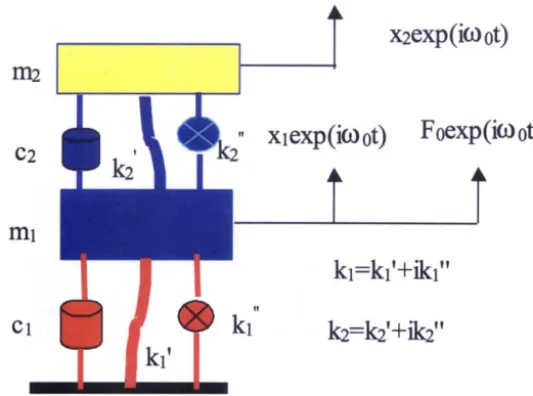
The excitation can be either base excitation or forced harmonic vibration with the excitation force amplitude F0. The force amplitude can be either constant or proportional to the square of frequency. If the circular frequency of the excitation that is denoted by tOo varies in narrow bounds and is situated outside the zones of resonance of the system with the vibration absorber, it is appropriate to use vibration absorber without the viscous or any other type of damping device and in the calculations the energy losses can be neglected. In case of wide band excitations and especially in case of resonance it is necessary to use vibration absorber with viscous or non-elastic internal friction resistance. The linear dynamic vibration absorber is presented in Figure 1:
SMiRT 16, Washington DC, August 2001
Paper # 1862
m 2
m
Y
xlexp(io~ ot)
x2exp(io3 0t)
Foexp(io3 or)
k l = k l ' + i k l ''
t!
cl k z = k z , + i k 2 ,,
Figure 1 Linear dynamic vibration absorber
The optimal parameters of the mass damper can be selected so that response property criteria of primary mass like x0, v0, ao,- displacement, velocity, acceleration amplitudes reach acceptable values.
VIBRATION ABSORBERS WITHOUT DAMPING DEVICES
The equation of vibration of the system depicted in Figure 1 without damping devices can be written in the matrix formulation as
Equation 3 [M] { Jc } + [K] {x} = [F];
where [M] is diagonal mass matrix with elements ml and m2 ; [K] is the stiffness matrix with elements kl, -k2 in the first row and -k2, k2 in the second row. Displacement vector {x} has elements Xl and x2 and excitation vector {F} has elements F0 exp(i030t) and zero. In matrix [K] the first element is approximated. The exact value for the first element is kl+k> It is assumed in this study that the ratio ml/m2 smaller than 0.05. Under this condition the approximation does not have any significant effect on the numerical results. Equation 3 is solved for particular solution by using trial vector in the form {x }T= {xlexp(i030t),0}. After the trial solution is substituted in Equation 3 and the term exp(i030t) is cancelled from both sides of equation the solution takes the form
Equation 4 X1 = (k2 -m20302)F0/A;
Equation 5 x2 = k2 F0/A;
Introducing the notation v= ml/m2, C012 --kl/ml, 032 2 = k J m 2 , f2 _ 0312/032 2, 032 __ 0302/0312 we get for non-dimensional displacement Xlkl/Fo and x2kl/Fo following expressions:
Equation 6 x 1k l/F0 =lc(f2-032)/AI; Equation 7 X2kl/F0 =lcf2/AI;
Equation 8 Vlkl/Fo/031 ---Ici03(f2-03a)/AI;
In case when the amplitude of the excitation force is constant c=l and in case when the amplitude of the excitation force is proportional to the square of 030 because of rotational unbalance excitation c=030 2. The two natural frequencies of the investigated vibration system are determined from the Equation 1 1:
Equation 1 1 031,2={1/2[l+f2(l+v)l+/-1/2{[l+f2(l+v)]2-4f2}l/2} 1/2.
k2
m2
t
x2exp(io3ot)
xlexp(iO3ot)
kl
xoexp(ioJot)
Figure 2 Base excited vibration absorber without damping devices
Xl
A
1 1 I I 2
A
Pl f P2 03
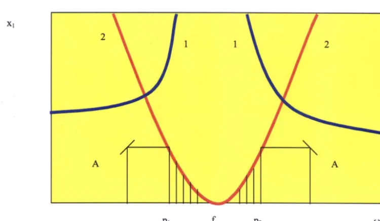
Figure 3 The response characteristics of dynamic vibration absorber; 1-response curve without secondary mass; 2- response curve with secondary mass
Using equations 4-10 the dynamic vibration absorber can be optimized so that ones the mass ratio v and the location of response checking points p~ and p2 are chosen the response A at points Pl and P2 and the tuning f of the absorber can be chosen optimally. First A is solved from the Equation 12:
Equation 12 v=(P22-P 12)/(Pl
2p22 ( ~2-~1));
where auxiliary parameters
t~land
~2 are given by Equations 13:Equation 13 ~1,2 = 1/(13+p 1,22-1 );
The values of the variable [3 in Equation 13 are given for constant amplitude harmonic excitation by Equations 14: Equation 14 [3=+/- l/A;
and for rotational unbalance excitation by Equations 15:
Equation 15 [3=+/-P1,2/A;
First sign in Equations 14 and 15 corresponds to 1~1 and second sign corresponds to q~2. The Equations 14 and 15 correspond to the case that for criteria of optimization in points Pl and P2 is the minimum displacement of the primary structure. Thus for optimal tuning the expression is given by Equation 16:
Equation 16
f2=p12p22(~2-~l)/(p22~2/p 12~1);
The introduction to the dynamic vibration absorber system the element of non-elastic resistance in form of intemal friction damping device or viscous damping device [2], [3] makes possible to decrease the resonance vibrations of main structure at the locations of split resonance peaks of the joint system. The approach used in determination of optimal parameters of the absorber device differs from the case of mass damper without internal friction or viscous damping device because it is necessary to determine the optimal tuning f2 and the damping ratio ~2 = c2/2/(m2k2)1/2 by the given value of v. If the damping of the main structure is neglected the f2opt and ~opt can be calculated in closed form. The main parameters of optimal mass damper with viscous damping device are given in Table 1:
Case
Constant amplitude excitation
f2opt
~22opt
1/(l+v) 2 3v/(2(l+v) 2)
Rotational unbalance excitation 1/(l+v) 3v/(1 +v)/(2+v)
Table 1 Optimal parameters of vibration absorber with viscous damping device
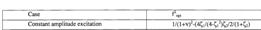
Quick look at the values given in Table 1 show that for realistic mass ratios of 0.02, 0.03, 0.04 and 0.05 the optimum tuning is slightly below unity and that the ~e2opt is about one and half times the value of the mass ratio v. The damping of main structure has effect on the amplitudes of the system and in lesser degree on the values of optimal parameters of the mass damper. If '~1 is the damping ratio of the main structure the approximately optimal tuning) can be calculated with the aid of formulas given in Reference [3]:
Case f2op t
Constant amplitude excitation 1/(1 +v)2-(4~1/(4-~12)~e/2/(1+~e) Rotational unbalance excitation (l+~12+l.5~1~e)/(1-~1)2/(l+v)
A quick look at the Table 2 shows that the effect of the primary system damping on the optimal tuning of the system is almost negligible. The primary and secondary system damping either by internal friction mechanism or by viscous damping mechanism can be taken into account in Equations 4-10 expressing the response of the joint system by following augmentation of the expressions. The Equation 6 obtains for the case of internal friction damping the form:
Equation 17 xlkl/F0
=
I(f2(1 +72i) -o32)/(((1+~tli ) _032)(f2(1 +72i) _032)
_vf4(1 +72i)^2)1All other response equations obtain forms that are received by same substitution as in case of equation 17 by replacing in Equation 6 1->(1 +i71) and f2_>f2(1 +i72). The Equation 6 obtains for the case of viscous damping the form:
Equation 18
Xlkl/F0 = I((f2+v032~2~2/~,i) _032)/(((1 +032~1i) -032)((f2+v032~2~2/~1i) _032) _vf4)l
All other response equations obtain forms that are received by same substitution as in case of equation 18 by replacing 1- >(1 +i032~1) and f2->(f2+iv032~2~2/~1) in the same places as in equation 17.
APPLICATION CASE OF DETERMINISTIC LINEAR DYNAMIC VIBRATION ABSORBER
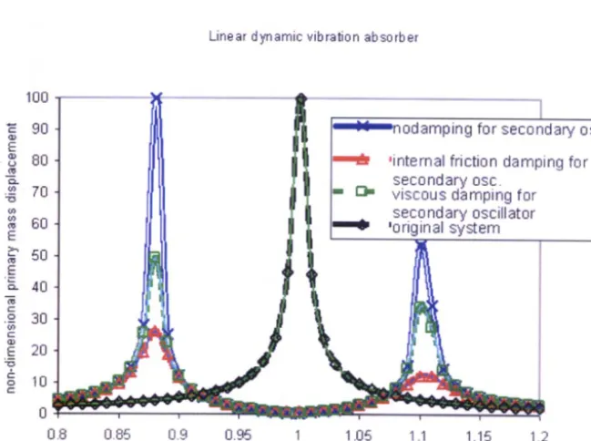
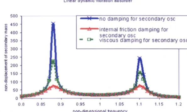
The numerical calculation table has been developed with the aid of spreadsheet program Excel [4]. In the following table and figures the response of the general linear dynamic vibration absorber is developed for mass ratio v=0.05. The deterministic trial value for tuning ratio f has been calculated from Equation 16 using values 0.95 and 1.05 for parameters pl and p2. The deterministic optimal trial value for f is 0.996. For internal friction damping case in this application example values of 71 =0.01 and ?2 =0.05 were selected. For viscous damping case in this application example values of ~1 = 0.005 and ~2 =0.025 were selected. In the following figures the displacement response of the primary and secondary masses are depicted:
Linear dynamic vibration absorber
100 t ...
90
ltt.I~:
...
-~' [
... + ... ' . ; ...nodamping for
secondary'
~i
osc.L~
80 4
jill
i~
t ~ : =
internal, friction damping for
-~
/
rl I
.~6 t
secondary osc.
# 7o 4
II
II
I" D.
viscousdamping
h5
~o
/
Ii 1t
? II t
secondary oscillator
t
i
i i ~
'ori-inal s,stern
i
.~ 30
~ 20
o
0.8
085
0.9
0.95
I
1,05
1,1
1.15
1.2
non-dimensional exciting frequency
Linear d y n a m i c vib~ation a b s o r b e r
500 - " " " ' = ' ) ¢ " " - n o --.--,..r-.. =d'~rnniqn f o r secondan/ osc
45o
~'-"~"-'it'~ter'~~al friction damping for
400
>- secondary osc
~ sso - t ~ viscous damping forseconda~.yosc
3 0 0
"o 250 I
200 I
150
~5 1 O 0
'- 5 0
0
0.8 0 85 0.9 0,95 1 1.05 t .'t 1.1 5 t .2
non-dim e n s i o n a i frequency
Figure 5 Secondary mass displacement response of deterministic vibration absorber
STOCHASTIC O P T I M U M F O R TUNING W I T H GIVEN L I M I T D I S P L A C E M E N T F O R P R I M A R Y MASS AND GIVEN T A R G E T R E L I A B I L I T Y
The optimal design of the harmonically excited structure with stochastic, dynamic vibration absorber is investigated. As we see from Figure 5 the maximum displacement of the primary mass occurs at lower split resonance peak. So we set displacement limit constraint at the location of lower resonance peak and require that the peak for harmonically excited primary structure equipped with dynamic vibration absorber is less than tenfold the static displacement caused by the harmonic force amplitude. Further we assume that the basic variables of the tuned mass damper, namely, mass ratio v, tuning ratio f, primary system damping ratio for internal friction damping 3'1 and secondary system damping ratio for internal friction damping 3'2 are stochastic variables having given probability distributions. In addition, we set the target reliability index value 13 = 2.5. The assumptions for the distribution types of the basic variables were non-correlated normals, correlated normals, non-correlated log-normals, and correlated log-normals. The adopted values for the distribution parameters and correlation coefficients are given in the following Table 3:
Variable Mean Coeff. of Variation Corr. coeff.
Mass ratio X l 0~05 0.10
Tuning ratio x2 To be determined 0.10 Pl,2 =0.4
Primary damp. coeff, x3 0.01 0.10
Secondary damp. coeff. X 4 0.05 0.10 P3,4 =0.4
Table 3 Distribution parameters for basic variables
Obtained results are the optimal mean values for tuning of the dynamic vibration absorber for the four different assumptions for basic variable distributions. The numerical calculations were carried out by the Solver utility of Excel [4] and verified by the Optimization Toolbox of Matlab [5]. The results are given in tabular format in Table 4:
Distribution Opt. Safety Limit exc.
Non-correlated normals 0.9515 2.5 0.00621
Correlated log-normals Correlated normals
0.9020 2.0 0.02275
1.0314 2.5 0.00621
Deterministic 0.996 NA NA
Table 4 O p t i m a l t u n i n g ratios f o r d i f f e r e n t d i s t r i b u t i o n s f o r b a s i c v a r i a b l e s
N U M E R I C A L S O L U T I O N O F N O N L I N E A R D A M P E R
One way to introduce the non-linearity to the vibration system investigated in previous sections is to pre-stress the spring of the tuned mass damper. In this case the spring force is given with the aid of the displacement of the spring using the following Equation:
Equation 19 k = k0( 1 +e/Ixl )
In Equation 19 k0 is the spring constant of the spring used in the damper and e is the pre-stress. The form of non- linearity to be investigated is the cubic Duffing - vibrator defined by the Equation:
Equation 20 k = ko (1 + l ~ x 3 )
The numerical solution of the vibration system with the spring definition of Equations 19 and 20 has been solved in this study with the aid of Wilson - 0 method. The solution algorithm was coded with the aid Excel and Matlab development tools.
The tuned mass damper non-dimensional response was solved numerically by direct integration and analytically by using one term Galerkin - method using the following parameter values for vibration system of Figure 1:
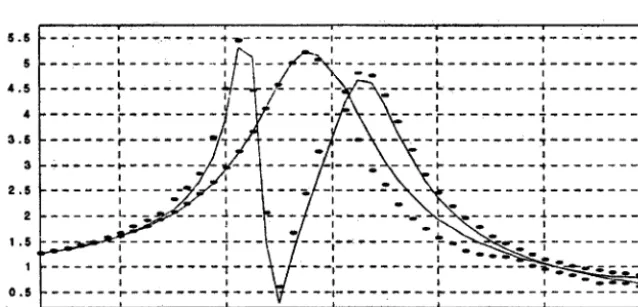
mt = 1, m2 =0.05, k't - 100, k'2 = 5, cl = 0.1, c2 =0, F0 -1. The non-dimensional response parameter is the of the f o r m X n o n _ d i m e n s i o n a I = k'lx/F0 and the non-dimensional frequency parameter is (0non_dimensiona i = O ) d O ) 1 . In Figure 6 the non-
dimensional response of cubic D u f f i n g - system with parameter values of e =0 and e =0.3 is given by dotted line. The solid line in Figure 6 is the one term analytical Galerkin solution:
-- . . . . '- . - T ~ ~ • < - : - - r - t . . . " " - = : . . . . - , J . . . :: -- - t . " -
5 . 5 - - - - . . . . t - . . . . - . . . . - ~ - o I I -t -
t I I /
_ _ _ ~ _ _a~:, . . . i. . .t
5 t. .t .
/ i.,. - ~ t I I
4 . 5 . _ ~ . . . . ~_N...,.,/Z'-~ . . . L . . t . t
+A--X
+'
,
l _ ~ / ' , , ,
, - - - - r - . . . . . . . . •
I ' I I t _ \ \ a . a . s ~
a . s . . . r . . . T . . . - ~ - - - ~ - - ~ - - - r " - ' ~ " ' r
! ! ° / 0 \ ' V I I I
3 :
,-
- ~ ] ' - -
I'4. . . /'/"'---
+. -X,-_ \-X_-.~ ,,- . • • ",", " +,, . , . . . , ~ - - _ - . - 7 1 - + - _ . ~ - - - , ~ - , . . . . _ - _ \ _ ~ . . . . + . . . +
_ _ ~ _ _ _ 4 _ _ ~ . . ~ . . . . . _ ~ , u ~ , . . . . t . . _ t
, . . . ~ : ~ ~ _ _ _ ~ _ L i ',. - \ , ~ ' '
~ I - - , - - -+ - - - ~ . c - ~ . ~ . + , , . . ,
" ~ . _ _ . ~ . . . . _ _ . _i.., . - # , . , \ - , ,
i . s - - . i . . . "+ - - t - - 7 - - ' , . . . r " T , . ' ~ ~ 7 . ' _ ' T " • -T
' -i' ~_ L___-.~_,_ ~ - ' - ~ . . . . ,
' . . . . ' . . . ~ - - - +~-r - - - ~ " + r . . . . " + ~
I I W I I I " ,i,
0 . $ . . . . I - " - - - - ~ . . . . ~ - - - - I . . . : . . . r . . . + . . . .
• " i_._ l . 1
• 0 . 6 0 . 8 1 1 . 2 1 . 4 1 6
F i g u r e 6 T h e n o n - d i m e n s i o n a l r e s p o n s e o f t h e t u n e d m a s s d a m p e r w i t h c u b i c Duffing - spring a n d w i t h p a r a m e t e r values of e= 0 a n d e = 0.3
C 0 . 4
tt
I ,=. - . , . ~ o
i
io e
I I 0 . 8
' ' ' ' ' I i ~ . , i ...
- - 1 - .... i - -
a- . . . . ' i , - - - ~" . . . . l . . . . a sF . . . . ~ ~ - - -~ . . . . -~ . . . .
~ , % ~ a I ':. I i a ~ A ~ 1 l . :
r• ' . '
- / , ~ -,---.~'
. . . . ' : '2 \ I ~ - ' 4.5 . . . . ~- - - 74-~ . . . ....
7 j T i i l ' : i
I ' ~ . * m , . t / i t i t If ' ~ i . s
. . . . f - , - - ~ - - r , .- - - , , " - - ". 1 • 41- . . . . ~ - - t - i - ' - - - t - ~ - - ~ % - ~ . . . . - ~ - " - - : : i ~ ~ ! .- , ' . t / I I ! I 1 I ~ \ i i "
3 ~ I . . ' -I-I t 4 - - ' - - ~. ~ ~ ' q k k ' J *
/ , %c~, , i I . . . . t"-77-'-~" I I ~ ~ 7 . . . . 7 . . . .
- - ~ - - i - - - ~ ; + . . . . i . . . . , / e I l S l ~ p i ~ ~ t "
. 7 , ~ , , : , ' , - - - , , - , - , , , - - . - - - , , - - - ' . ' - - "
I i ",t,t u I
' / , ~ , , 2 . ~ I - . . . . '-. 4 . . - ~ - / - . - - - ' . . . . %.I.* . . . . J - - - - - / ' / .,,'l J / ' \ | , • t • ..,,/: - - - ~ . . . % - - - - ' - - - . : ..!.:
! t 2 . . . - . . . ",~-- -~ - -
I I
_ _ : _ , , ~ ~ - - - , : . . . : . . . . _ : : , ~ _ : . . . .
, ;,
', -"=,
'[
! ...
!---'-i
....
I I J" I I l I
I :1 . :~ OS . . . . l ~ . l . . ,! I
0 , 8 1 " I 2 ' - - I ; 4 .-11.§ 0 . 4 0 . 8 0 . 8 1 1,2 1.4 1.6
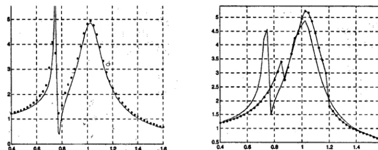
F i g u r e 7 T h e n o n - d i m e n s i o n a l r e s p o n s e o f t h e t u n e d m a s s d a m p e r w i t h p r e - s t r e s s e d s p r i n g a n d w i t h p a r a m e t e r v a l u e s o f e = 0 a n d e = 1.9
CONCLUSION
The optimal choice of the n o n - linear tuning parameters of the tuned mass damper appears to be very sensitive small changes in the parameters. The reported study is an on - going effort and the results obtained so far point towards the possibility of replacing the viscous or internal friction damping devices of Figure 1 with non-linear spring characteristics in the spring of the damper.
REFERENCES
.
3.
.
5.
Spravochnik proektirovshika, Dinamicheskyi raschet sooruzhenyi na spetsialnye vozdeistviya, eds. B.G. Korenev, J.M. Rabinovich, Moscow, Stroiizdat, 1981.
J. P. den Hartog, Mechanical Vibrations, New York, 1960.
L.M. Reznikov, 'Vybor optimalnih parametrov dinamicheskix gasitelei kolebanii s razlichnymi vidami soprotivlenii', Problemy prochnosti, 1970, No. 9.
Microsoft Excel, User's Guide, Version 7.0, Microsoft Corporation, 1997.