MODELING & SIMULATION OF OPEN LOOP PULSATING HEAT PIPE
B.Gera, P.K.Sharma, R.K.Singh
Reactor Safety Division, Bhabha Atomic Research Centre, Mumbai, INDIA-400085 E-mail of corresponding author: [email protected]
ABSTRACT
Pulsating Heat Pipe is a new concept in the field of heat exchangers that aims at extraction of large amounts of heat from comparatively small heat transfer areas in continuous modes. The device is passive in nature in the sense that it doesn’t involve use of any external power for pumping the working fluid. Moreover it can work in absence of gravity as well as in vacuum. PHP is a bend tube of capillary dimensions with either closed ends (open loop) or the two ends connected to form a closed loop. Vacuum is created inside the tube and working fluid is filled so that it flashes to form vapor plugs and liquid slugs. When this unit is placed between heat source and sink it serves as an efficient medium to transfer heat due to the pulsations present to pump the liquid slugs that serve as means of sensible heat careers.
This present work is to study the phenomena taking place inside a pulsating heat pipe based on basic conservation laws of mass, momentum and energy for vapor plugs and liquid slugs; and thermodynamic aspects pertaining to it. A mathematical model was developed to simulate the physics behind the working of open loop pulsating heat pipe. The model on pulsating heat pipe is the very first attempt at RSD in India. The model tracks the motion of the plugs and slugs by determining their mass, temperature, pressure and velocity. Effect of gravity and surface tension force were also considered in modeling. The results are in good qualitatively agreement with those of the newly evolving models of the contemporary research in this field and the experimental observations made from actual working model of an open loop pulsating heat pipe. The effect of the various model parameters i.e. different working fluids, pipe diameter, filling ratio on its working were also looked upon to understand the characteristics of PHP.
INTRODUCTION
Pulsating Heat Pipe is a new concept in the field of heat exchangers that aims at extraction of large amounts of heat from comparatively small heat transfer areas in continuous modes. The device is passive in nature in the sense that it doesn’t involve use of any external power for pumping the working fluid. Moreover it can work in absence of gravity as well as in vacuum. PHP is a bend tube of capillary dimensions with either closed ends (open loop) or the two ends connected to form a closed loop. Vacuum is created inside the tube and working fluid is filled in partially, so that it flashes to form two phases, vapor plugs and liquid slugs. When this unit is placed between heat source and sink it serves as an efficient medium to transfer heat due to the pulsations present to pump the liquid slugs that serve as means of sensible heat careers. These structures have the following basic features:
(a) Meandering tube of capillary dimensions with many turns. This tube may be configured in any of the three forms: (i) Closed ends-Open Loop(CEOLPHP/CEPHP) : tube ends are closed and are not connected to each other or, (ii) Open ended-Closed Loop (OECLPHP/CLPHP): tube ends are connected to each other to form an endless closed loop. (iii) Closed loop PHP with a check valve (CLPHPW/CV) that incorporates one or more check valves in the loop.
(b) There is no internal wick as in conventional heat pipes.
(c)At least one heat-receiving (evaporator) and heat dissipating (condenser) zone is present; an adiabatic section may or may not be there in-between.
closed system; it has good reliability in terms of radiation shielding prevention of radioactive fluids exposed to the outside world.
The physical and mathematical models that have already been published in literature may be categorized according to the simplification scheme adopted. These may be summarized as follows:
• comparing a PHP action to an equivalent single/multiple spring-mass damper system [1]; • applying governing equations to a specified PHP control volume [2-6];
• modeling that takes into account the chaotic feature; • modeling by artificial neural networks [7];
• modeling by semi-empirical correlations based on dimensionless numbers [8]; and • modeling by the effect of capillary tubes and liquid film phenomena [9].
Some features of the pulsating action of a PHP have been compared to the action of a spring mass-damper system. Zuo and North [1] represented it in the form of a second-order homogeneous differential equation with a time-dependent spring constant. The solution of the differential equation suggests that the spring stiffness coefficient increases with time for the entire range of filling ratios. Thus, the amplitude of oscillations has to decrease. Swanepol et al. [2] applied the governing equations of mass, momentum, and energy to a simplified PHP model consisting of a liquid slug in the middle, two vapor bubbles at both ends, and a liquid film separating the inside tube wall from the bubbles. After comparing the results from this model to the experimental results, it was found that the position of the liquid slug in the experiment reached the maximum value faster than that of the. The tendencies of the movement of liquid slug could be predicted with some degree of accuracy. Sakulchangsatjatai et al. [3] have constructed the mathematical model of a CEPHP with a bottom heat mode at different inclination angles. The solution for all of the basic governing equations of liquid film, liquid slugs, and vapor plugs, in which the effects of surface tension, viscous friction of the working fluid, and perfect gas were included, has been numerically obtained by solving a series of ordinary differential equations by means of the explicit method. It was noted that the maximum heat transfer rate of the CEPHP with bottom heat mode occurred at the highest evaporator temperature (150 0C for this study) and inclination angles of 70–80 degrees from horizontal axis. Shafii et al. [4, 5] introduced a numerical model using governing equations including the continuity, momentum, and energy equations for looped and unlooped pulsating heat pipes. They first investigated the effect of the number of vapor plugs and liquid slugs and found that eventually the number of vapor plugs reduces down to the number of evaporator sections. In their second model [5], the thin film evaporation and condensation models have been incorporated with the model to predict the behavior of vapor plugs and liquid slugs in the PHP. The results show that heat transfer in both looped and unlooped PHPs is due mainly to the exchange of sensible heat, and the contribution of evaporation and condensation heat transfer is less than 5% of the total heat transfer rate.
Arabnejad et al. [6] have investigated the performance of a U-shaped pulsating heat pipe (PHP) using numerical methods. The governing equations are derived analytically from the continuity, momentum, and energy equations and are solved implicitly. In this model, considering the liquid mesh, the rate of convection and boiling heat transfer in the U-shaped PHP, which has not been investigated as of yet, are examined. The results show that by increasing the evaporator temperature, due to the increase in pulse amplitude and frequency, the rate of heat transfer due to convection and boiling in the pipe will increase too. An artificial neural network (ANN) is a processing device, either an algorithm or actual hardware. ANN modeling has been successfully applied to predict the performance of a PHP, and an experimental setup for the validation of the model has also been built [7]. In the comparison between the results from this model and the experimental results, it was found that the thermal resistance increased when the filling ratio increased or the heat input decreased. Heat transfer in the evaporator and condenser sections of an open-ended pulsating heat pipe was modeled by analyzing thin film evaporation and condensation [9]. The simulation results showed that the heat transfer in a PHP is mainly due to the exchange of sensible heat. The amplitude of oscillation decreases with a decrease in diameter or a decrease in heat wall temperature. Although there already exists a large number of mathematical models, most of them are based on some unrealistic model that does not correspond to the full behavior of the working fluid inside a CEPHP, and all of the existing models cannot be applied to CEPHPs with bottom heat mode at several inclination angles. Further corrections and improvements with respect to the effect of surface tension as well as the increase in number of vapor bubbles generated in liquid slugs (nucleate boiling) and phenomena of evaporation inside the liquid film are required.
WORKING PRINCIPLE
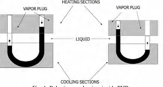
system. The liquid and vapor slug transport is because of the pressure pulsations caused in the system. Since these pressure pulsations are fully thermally driven, because of the inherent construction of the device, there is no external mechanical power source required for the fluid transport. Generally there are heating, adiabatic and condensation sections. The heating section receives heat and the condensation section rejects heat to the heat sink or environment. The adiabatic section separates the heating and condensation sections. The surface tension dominates the flow and heat transfer inside the capillary tube. The pulsation mechanism is shown in Fig. 1.
Fig. 1: Pulsation mechanism inside PHP
In actual working PHP, there are pressure and temperature gradients between the heating and condensation section. Temperature differences also exist amongst the “U” bends within the evaporator and the condenser due to local non uniform heating and cooling rates which are always expected in the real systems. The net effect of all these temperature gradients within the system is to cause non equilibrium pressure condition which, as stated earlier, is the primary driving force for thermo-fluidic transport. In addition to these, heat received from the heating section leads to uneven pressure distributions among the parallel channels due to the uneven vapor expansion in the parallel channels resulting from the unevenly distributed vapor plugs in the parallel channels. Such pressure differences between the heating and condensation section, and among the parallel channels, result in fluid transport among the parallel channels. Therefore self-sustained thermally driven oscillating flow is maintained in a PHP. Once thermally driven oscillating flow is initiated inside the whole PHP, heat is transferred from the heating section to the condensation section by the oscillating two-phase convection. Boiling takes place in the heating section, while condensation occurs in the condensation section. The working process of the PHP is a dynamic one, quite distinct from that of the conventional micro-heat pipes using wick structures.
THEORETICAL MODEL
The heat transfer in CEPHP can be predicted by solving mass, momentum and energy equations for each liquid slug and vapor plug. The appropriate maximum inner diameter of CEPHP can be calculated by
D≤1.84 σ/(g(ρl −ρv)) (1) Assumptions:
1. Evaporative and condensation overall heat transfer coefficients are assumed to be constants.
2. The liquid slugs assumed to be incompressible and the vapor plugs are free to expand and contract also to move. 3. The vapor pressure in the each vapor plug is constant and pressure losses at the bends can be neglected so it can be assumed that the CEPHP are straight.
4. The amount of liquid slugs corresponds to the number of turns. The length of the liquid slug along the centerline of the tube is dependent on the filling ratio.
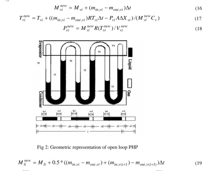
The geometry of the PHP is depicted in Fig. 2. The volume of the vapor plug and liquid slug may be written as
V
vi=
L
viπ
d
2/
4
and/
4
(2) 2d
L
V
li=
liπ
The mass of the vapor plug and liquid slug may be written as
The rate of change of mass of the vapor plug and liquid slug can be found from the following equations:
dM
vi/
dt
=
m
in,vi−
m
out,vi anddM
li/
dt
=
m
in,li−
m
out,li (4)It is assumed that the rate of change of mass of liquid slug is equal to the average changes in mass of its adjacent vapor plugs.
dM
li/
dt
=
(
dm
vi/
dt
+
dm
v(i+1)/
dt
)
/
2
(5)where
m
in,vi=
U
eπ
dL
eli(
T
h−
T
li)
/
h
fg andm
out,vi=
U
cπ
dL
cvi(
T
vi−
T
c)
/
h
fg (6)Assuming appropriate values for the evaporative overall heat transfer coefficient, and the condensation overall
heat transfer coefficient,
,
the momentum equation for ith liquid slug is:e
U
c
U
dM
liv
li/
dt
=
(
p
vi−
p
v(i+1))
A
−
π
dL
liτ
li−
mg
lig
(7)Since it is assumed that the CEPHP is a straight tube, gravity has different signs at different locations. In this model, the gravity force can be determined by measuring the difference in level between both ends of the liquid slug.
τ
liis the shear stress acting between ith liquid slug and the wall tube and can be determined from
τ
li=
0
.
5
*
C
liρ
lv
li2 (8) Where the friction coefficientC
li depends on Reynolds number. The energy equation for a vapor plug is:
M
viC
vdT
vi/
dt
=
(
m
in,vi−
m
out,vi)
RT
vi−
P
viAdX
vidt
(9)
P
viV
vi=
M
viR
(
T
vi)
(10) Heat transfer in the CEPHP is defined as the total heat transferred from the evaporator sections to the condenser sections. It can be divided into two parts; first the heat transfer is due to the evaporation and condensation of the working fluid at vapor phase. The heat transferred into and out of the vapor plug is:Q
in,vi=
m
in,vih
fg andQ
out,vi=
m
out,vih
fg (11)second, heat transfer between the tube wall and the liquid slugs is obtained by solving the energy equation for a liquid slug
(
1
/
α
l)
*
dT
li/
dt
=
d
2T
li/
dX
2−
h
liπ
d
(
T
li−
T
w)
/(
k
lA
)
(12) The boundary conditions of the liquid slug temperature are:X
=
X
rei;
T
li=
T
vi andX
=
X
le(i+1);
T
li=
T
v(i+1) (13)The heat transfer coefficient can be determined by Nusselt number. For small Reynolds, laminar
regime , Nusselt number is considered as thermally developing Hagen–Poiseuille flow. In the transition
and turbulent regions, the empirical equation used is different. The expressions used for the various regimes are as follows:-
li
h
2200
Re
≤
For laminar regime
Re
≤
2200
:Nu
=
3
.
657
+
(Re
Pr
D
/
L
)
0.8/(
1
+
0
.
117
(Re
Pr
D
/
L
)
0.467)
For transition regime
2200
<
Re
≤
10000
:
Nu
=
0
.
012
(Re
0.87−
280
)
Pr
0.4(
μ
l/
μ
w)
0.11(
1
+
(
D
/
L
li)
0.33)
For turbulent regime
Re
>
10000
:Nu
=
0
.
0236
Re
0.8Pr
0.43(
μ
l/
μ
w)
0.23 The total heat transferred into and out of the liquid slug between the wall of the tube and the liquid slug is:=
∫ (+1)(
−
)
;
>
and(14)
,
,li XXreilei li liX w li w
out
dh
T
T
dX
T
T
Q
π
=
∫ (+1)(
−
)
;
≤
,
,li XXreilei li w liX li w
in
dh
T
T
dX
T
T
Q
π
the temperature of the ith liquid plug at location
X
, , is obtained by solving the energy equation. The total heat transferred into and out of the CEPHP can be defined as:X li
T
,and (15)
li in N
i vi in N
i in
total
Q
Q
Q
, 1
1 , 1
, ∑ ∑
−
=
=
+
=
li out N
i vi out N
i out
total
Q
Q
Q
, 1
1 , 1
, ∑ ∑
−
=
=
+
An explicit finite difference scheme was used to solve the governing equation for the vapor and liquid phase. The time step used in all numerical simulations are 10-6 s because when varying the time step to 10-5 s the result is less than 0.3% in the location of the liquid slug. The new values at time step
t
+
Δ
t
can be determined from the old values at timet
byM
M
vim
invim
outvit
(16) newvi
=
+
(
,−
,)
Δ
((
, ,)
)
/(
v)
(17) newvi vi vi vi
vi out vi in vi
new
vi
T
m
m
RT
t
P
A
X
M
C
T
=
+
−
Δ
−
Δ
P
vinew=
M
vinewR
(
T
vinew)
/
V
vinew (18)Fig 2: Geometric representation of open loop PHP
M
M
lim
invim
outvim
inv im
outvit
(19) newli
=
+
0
.
5
*
((
,−
,)
+
(
, (+1)
−
, (+1))
Δ
li li vi vi li li li linew (20) new
li
M
v
P
P
A
dL
mg
g
t
M
v
=
(
+
((
−
(+1))
−
π
τ
−
)
Δ
)
/
The new valves replaced the old valves and the procedure was repeated for the next time step. The locations of the vapor bubble and liquid slug can be known by the location of their ends. For CEOPHP the new position of each vapor plug is defined as
X
reinew=
X
rei+
v
liΔ
t
;
X
leinew=
X
lei+
v
l(i−1)Δ
t
;
X
reN=
L
;
X
le1=
0
(21)
RESULTS AND DISCUSSIONS
0.0 0.5 1.0 1.5 2.0 8.00E-009 1.00E-008 1.20E-008 1.40E-008 1.60E-008 1.80E-008 2.00E-008 MASS ( k g s ) TIME(secs)
0.0 0.5 1.0 1.5 2.0
-2.0 -1.5 -1.0 -0.5 0.0 0.5 1.0 1.5 2.0 VEL OC IT Y (m /s ec ) TIME (secs)
0.0 0.5 1.0 1.5 2.0
280 300 320 340 360 380 400 TEM PER ATUR E( k e lv in ) TIME (secs)
Fig. 3: Mass (left), velocity (middle) and temperature (right) of 1st vapour plug with time for base case
0.0 0.5 1.0 1.5 2.0 2000 4000 6000 8000 10000 12000 14000 PR ES SU R E ( Pa ) TIME(secs)
0.0 0.5 1.0 1.5 2.0
0 20 40 60 80 100 120 HEA T OU T P UT ( w att s ) TIME (secs)
0.0 0.5 1.0 1.5 2.0
-5 0 5 10 15 20 25 30 35 HE AT I N PU T( w a tts) TIME (secs)
Fig. 4: Pressure of 1st vapour plug (left), total heat transferred (middle) and total heat taken (right) with time for base case
The effect of change in diameter
The inner diameter of PHP was increased to 2.5 mm keeping other parameters same. The results obtained for this case are shown in Fig. 5-6. It can be seen that by increasing the inner diameter, heat flux will increase. This is because when a tube inner diameter is large, the boiling phenomena will be like the pool boiling phenomena in which its heat transfer coefficient is higher than that of the boiling inside a confined channel with a small inner diameter.
The effect of change in filling ratio
After the analysis of results of the run for a filling ratio of 55% it has been observed that oscillations take some time to settle before attaining the stability in frequency and amplitude. Moreover the heat transfer rate also increases to some extent due to the rise in sensible heat taken and transferred by the liquid slugs which are larger in this case as compared to the case of 45% filling. The filling ratios of above 65% cannot sustain healthy oscillations and hence the heat transfer is poor, whereas the filling ratios below 40% are less effective because of the lesser contribution of sensible heat in the total heat transferred by the PHP.
The effect of change in working fluid
0.0 0.5 1.0 1.5 2.0 -2 -1 0 1 2 VEL O C IT Y (m/sec) TIME (secs)
0.0 0.5 1.0 1.5 2.0
280 300 320 340 360 380 400 TEMP ER A T U R E (kelvin ) TIME (secs)
0.0 0.5 1.0 1.5 2.0
1.50E-008 2.00E-008 2.50E-008 3.00E-008 3.50E-008 4.00E-008 4.50E-008 5.00E-008 5.50E-008 6.00E-008 MAS S ( k g) TIME(secs)
Fig. 5: Mass (left), velocity (middle) and temperature (right) of 1st vapour plug with time for inner diameter 2.5 mm
0.0 0.5 1.0 1.5 2.0 -20 0 20 40 60 80 100 120 140 160 180 HE A T IN P U T (wa tts) TIME(secs)
0.0 0.5 1.0 1.5 2.0 0 50 100 150 200 250 HE AT OU T P UT (wa tt s ) TIME (secs) 0.0 0.5 1.0 1.5 2.0
2000 4000 6000 8000 10000 12000 14000 PRES SUR E (Pa ) TIME (secs)
Fig. 6: Pressure of 1st vapour plug (left), total heat transferred (middle) and total heat taken (right) with time for inner diameter 2.5 mm
CONCLUSION
Thermal modeling of CEPHPs with multiple vapor plugs and liquid slugs was performed, and the behaviors of liquid and vapor plugs in the PHP were investigated. The total number of vapor plugs reduced to the total number of heating sections, no matter how many vapor plugs were initially in the system. Periodic oscillation was obtained under specified parameters. Heat transfer in CEPHPs is due mainly to the exchange of sensible heat. The role of evaporation and condensation on the performance of the CEPHPs is mainly on the oscillation of liquid slugs. By increasing the diameter of the CEPHPs the total average heat transfer increases and CEPHPs did not operate for higher charging ratios.
NOMENCLATURE:
A tube cross sectional area, m2 Cl fiction coefficient
Cp specific heat (constant pressure), J/kg K
Cv specific heat (constant volume), J/kg K
d diameter, m
g acceleration due to gravity, m/s2 h heat transfer coefficient, W/m2 K hfg latent heat of vaporization, J/kg
k thermal conductivity, W/m K
L length, m
Lel length of liquid slug in the heating section, m
Lcv length of vapor plug in the cooling section, m
m mass flow rate, kg/s
Nu Nusselt number P pressure, N/m2
Pr Prandtl number
Q heat transfer rate, W R specific gas constant, J/kg K Re Reynolds number
T temperature, K
t time, s
U overall heat transfer coefficient, W/m2 K V volume, m3
v velocity, m/s
X distance
Greek Letters
αl thermal diffusivity of liquid, m2/s
µ dynamic viscosity, kg/m-s
σ surface tension, N/m
ρ density kg/m3
shear stress, N/m2
Subscripts
X distance in inlet li ith liquid plug le left end out outlet re right end vi ith vapor plug l liquid v vapour w wall
REFERENCES
[1] Zuo, Z.J., and North, M.T., “Miniature high heat flux heat pipes for cooling of electronics”, Proc. SEE, Hong Kong, China, 2000, pp. 573–579.
[2] Swanepol, G., Taylor, A.B., and Dobson, R.T., “Theoretical modeling of pulsating heat pipes”, Proc. 6th
International Heat Pipe Symposium, Chiang Mai, Thailand, 2000, pp. 358–365.
[3] Sakulchangsatjatai, P., Chareonsawan, P., Waowaew, T., Terdtoon, P., and Murakami, M., “Mathematical
modeling of closed-end pulsating heat pipes operating with a bottom heat mode”, Heat Transfer
Engineering, Vol. 29, 2008, pp. 239–254.
[4] Shafii, M.B., Faghri, A., and Zhang, Y., “Thermal modeling of unlooped and looped pulsating heat pipe”,
ASME Journal of Heat Transfer, Vol. 123, 2001, pp. 1159–1172.
[5] Shafii, M.B., Faghri, A., and Zhang, Y., “Analysis of heat transfer in unlooped and looped pulsating heat pipes”, International Journal of Numerical Methods for Heat & Fluid Flow, Vol. 12, 2002, pp. 585–609. [6] Arabnejad, S., Rasoulian, R., Shafii, M.B., and Saboohi, Y., “Numerical investigation of the performance of
a U-shaped pulsating heat pipe”, Heat Transfer Engineering, Vol. 31, 2010, pp. 1155–1164.
[7] Khandekar, S., Cui, X., and Groll, M., “Thermal performance modeling of pulsating heat pipe by artificial neural network”, Proc.12th International Heat Pipe Conference, Russia, 2002, pp. 215–219.
[8] Khandekar, S., Charoensawan, P., Groll, M., and Terdtoon, P., “Closed loop pulsating heat pipes, Part B: visualization and semi-empirical modeling”, Applied Thermal Engineering, Vol. 23, 2003, pp. 2021–2033. [9] Zhang, Y., and Faghri, A., “Heat transfer in a pulsating heat pipe with open end”, International Journal of