Implementation of Downlink Visible Light
Communication using LED and Photodiode
Havisha Kalwad
1, Poornima B.K.
2P.G. Student, Department of Electronics and Communication, Dayananda Sagar University, Bangalore, India1 Assistant Professor, Department of Electronics and Communication, Dayananda Sagar University, Bangalore, India2
ABSTRACT: In this paper we present the initial design, implementation and result of a small-scale prototype of Visible Light Communication using simple LED and a photodiode. Data is transmitted through visible light by sending data in a binary format as on and off that varies in frequency faster than the human eye can follow. The data to be transmitted is encoded and sent. The data is decoded back at the receiver. Visible Light Communication is the latest technology for communication as it eliminates the use of a radio channel and it is much more secure. This implementation aims to attain an efficient and reliable communication link with considering sufficient improvement with the factors of trade-off such as the distance between the transmitter and receiver for communication and to attain the fastest possible data rate.
KEYWORDS: visible light communication; binary data; encoding; LED; photodiode; decoding.
I. INTRODUCTION
Visible Light Communication (VLC) is a subset of Optical Wireless Communication which uses visible light spectrum of 390-790 THz frequency. It provides low-cost, energy efficient wireless solution to obtain higher data rates. VLC uses Light Emitting Diode (LED) operating at a varied frequency.
The advantage of using VLC is that it uses light as a communication medium which is much faster than radio. It has a bandwidth of about 400THz which is about thousand times greater than that of radio having 300 GHz. It does not require any additional infrastructure and is very much secure compared to radio. The most probable secure usage in the near future would be in the banks or corporate infrastructures or any location which requires a secure infrastructure.
Initial works are based on simple modulation techniques such as On-Off Keying (OOK), Pulse Position Modulation (PPM) and so on. OOK and PPM have been selected as the modulation schemes for IEEE 802.15.7 standard in 2011. Colour Shift Keying (CSK) has also been added to the list recently.
II. RELATED WORK
VLC has become a popular research topic because of its potential applications in commercial and residential buildings, corporate offices as it is a cheap and effective way to communicate using LEDs.
Work cited in [6] provides an overview of the existing VLC systems. Examples cited in [1], [2] and [3] explain the mechanism to convert a pre-recorded audio into binary stream and transmit using flashlight. A camera is used as a receiver to detect the switching of the flashlight and decode the received information. Work cited in [4] also uses a camera and a flashlight. Work cited in [5] indicates the communication between two toys using LED and a photodiode.
From the literature survey we conclude to attain a prototype version of downlink visible light communication using an LED and a photodiode as photodiode would help attain the fastest data rate with good efficiency. The problem statement for this project is to implement a downlink Visible Light Communication link to establish a reliable, fast and efficient data transfer between the light source and the receiver.
The rest of the paper is organized as follows. Section III contains the system overview which gives the components required and the proposed block diagram for the implementation. Section IV and V explain the details of the component description and implementation respectively. Section VI gives the details of the algorithm or the modulation scheme used for this implementation. Section VII explains the results obtained. Section VIII gives a conclusion to the parameters achieved in this project. Section IX explains the parameters to be achieved as future work. Section X gives the list of references which have been a major contribution to this implementation.
III.SYSTEM OVERVIEW
The proposed system in this paper requires a transmitter and a receiver with encoding and decoding capabilities. In this system the data is transmitted using white LED/visible light. The details of the transmitter and receiver are given in the next session. The proposed system is a basic prototype of the VLC system built using Arduino platform.
Components Required:
Arduino Uno Board, connecting wires, white LED, resistors, photodiode, USB cable.
Block Diagram:
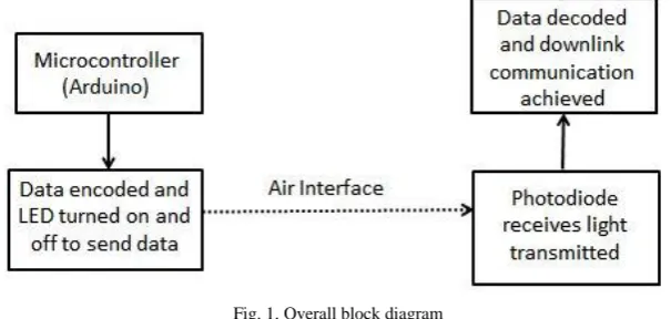
Fig. 1 shows the overall/generic block diagram which gives the gist of the project. On the left side the transmitter sends the data of any form converted to binary format. On the right side is the receiver which receives the binary data and successfully completes the visible light communication prototype.
Fig. 1. Overall block diagram
IV.COMPONENT DESCRIPTION
V. IMPLEMENTATION
The transmitter LED is made to turn ON and OFF at a very high frequency. Hence, the light seems to be always on to the human eye and the data transmission also takes places simultaneously. The data of ASCII type is converted into binary format. This binary value is the data used for transmission. The data value is appended with a start bits and stop bits for the start and stop indication of the data packet and then the data packet is then stored separately in a buffer. Fig. 1 shows a general block diagram approach for this project.
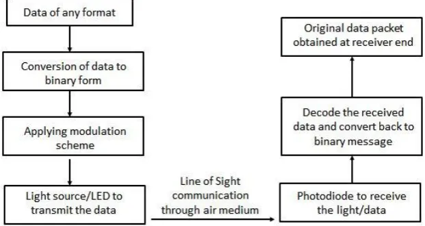
The white LED light which is made to turn ON and OFF at a very high frequency is been received by the photodiode. The transmitter and receiver are made to sync with the same delay given in both the transmitter and receiver codes. The data packet reception is initiated upon first receiving the four-bit start bit. The entire data packet is stored in a receiver buffer. The reception window closes upon receiving the ten-bit stop bit. The data frame from the following data packet is removed and demodulated. After demodulation, the data frame is split into multiple frames of each 8-bits. Each of these 8-bit frames are then converted back to their ASCII values to obtain the original data transmitted. Fig. 3 shows the complete setup of transmitter and receiver. Fig. 2 shows implementation level block diagram. In the implementation level block diagram of Fig. 2, on the transmitter side the data is converted into binary format and a modulation scheme is applied. Here, Manchester modulation is applied. On the right/receiver side, the photodiode receives the data and decodes it to get the original message transmitted. The current distance of operation is set at maximum 8 centimetres.
Fig. 2. Implementation level block diagram
VI.MODULATION SCHEME
When a colour sensor is used in Colour Shift Keying (CSK), the blue and yellow light act as the transmission of 1s and 0s. On-Off Keying is a very common modulation scheme for binary data modulation. OOK and PPM have been selected as the modulation schemes for IEEE 802.15.7 standard in 2011. The modulation is implemented with a timer program to generate an accurate delay of 1 millisecond between each bit.
clock pulse. The frequency of clock pulse is double of that of the data stream. The data stream is modulated by XOR operation on the rising and falling edge as shown in Fig. 3.
Fig. 3. Manchester Encoding on binary data stream
VII. RESULTS
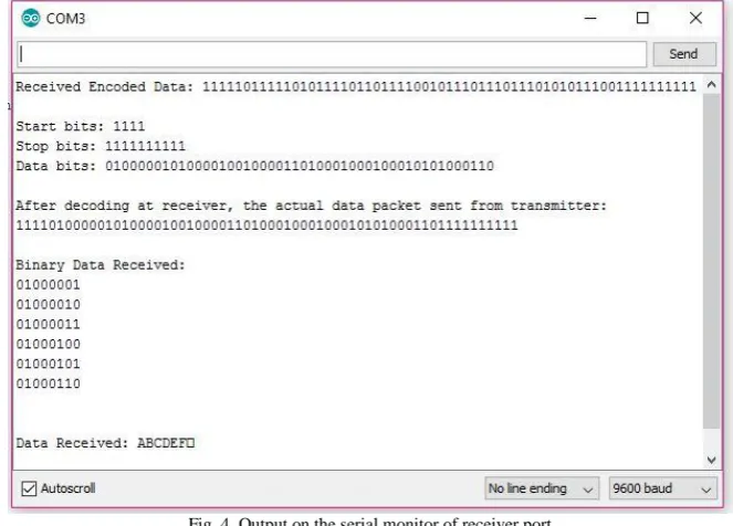
The VLC system implemented uses BPW-45 photodiode along with a simple white LED operating at a maximum distance of 8 centimetres. The photodiode’s maximum receiving speed when connected to an Arduino board and serial terminal is about 500 bits/sec. Hence, using this photodiode efficiently with a very efficient and modified code, one must be able to obtain a data rate of 500 bits/sec upon connecting to Arduino. Fig. 4 indicates the output on the serial monitor for the receiver side. The receiver serial monitor indicates the received encoded bits, the entire data packet along with the start bits, data packet and the stop bits and also the received message.
Fig. 4. Output on the serial monitor of receiver port
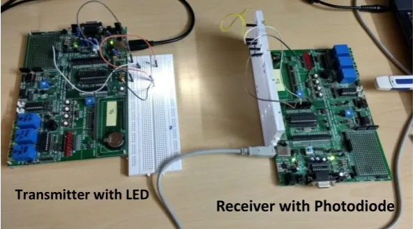
In our implementation, we have applied Manchester encoding scheme and also subjected the code to many such similar operations which has reduced the efficient and reliable detection rate without any errors to 500 bits/sec. With the current code efficiency, we are able to send data at 500 bits/sec without any data loss. Fig. 5 shows the hardware setup for the transmitter and receiver used. The left hand side is the transmitter with Arduino microcontroller and LED to transmit the data through light. Right hand side is the receiver with photodiode which is connected to the Arduino microcontroller.
Fig. 5. Hardware setup for the experiment with Arduino transmitter and receiver along with LED and photodiode
Figure 4 shows the serial monitor image for the transmission/data send after applying Manchester encoding. Figure 4 also shows a detailed split up of the received bits. First the data packet arrives. The start and stop bits are stripped from the data packet and the obtained data packet is decoded to get our original data packet. This data packet is then split into multiple 8-bit frames to further convert them into respective ASCII values.
VIII. CONCLUSION
In this paper, using a photodiode, we could obtain a data rate of 500 bits/sec with a maximum character count of 42. Using a photodiode with a better switching time we can further enhance the speed of transmission.The same setup can also be done using a camera. The maximum frame rate of the camera must be double the maximum transmission rate to avoid the possibility of data loss. An important factor to consider in this scenario is the stability of the camera’s frame rate. For our setup using a photodiode, the environmental considerations taken into account is the ambient light of the room. In a room that is very brightly lit, we would have to change the threshold considerations for the photodiode and also the distance between the transmitter and receiver has to be reduced for greater focus. This system later can be ported to a variety of applications such as vehicle-to-vehicle communications or product description model for the customers in a mall or museum and so on
IX. FUTURE WORK
The VLC system implemented in this paper is of Line of Sight considerations. The delay introduced in the transmission is to ensure a proper synchronization between the transmitter and receiver. This factor has reduced the transmission speed greatly. Upon using other implementation techniques we can reduce the delay factor. We can perform the decoding and buffer update operations instead of the idle delay time. In future, we shall use RTOS based implementation to improve the data rate and also help to increase the efficiency and reliability.Using a microcontroller such as ARM LPC1768, the data rate can be increased by many folds.
Transmitter with LED
REFERENCES
[1] Green. J., Pridmore, T., Benford, S., Ghali, A., "Location and Recognition of Flashlight Projections for Visual Interfaces," Pattern Recognition, 2004. ICPR 2004. Proceedings of the 17th international Conference on, Vol.4, pp.949,952, 23-26 Aug. 2004.
[2] Ghali, Ahmed, et al. "Visually Tracked Flashlights as Interaction Devices."Proceedings of iNTERACT. 2003. [3] Ghali, Ahmed, et al. "Vision-Mediated Interaction with the Nottingham Caves."Proceedings of SPIE., Vol. 5022. 2003.
[4] Green, Jonathan, et al. "Camping in the Digital Wilderness: Tents and Flashlights as Interfaces to Virtual Worlds." CHr02 extended abstracts on Human factors in computing systems. ACM, 2002.
[5] Ilyas, Othman, Ali, “Two Toys Vehicles Interactions Using Communication Protocol for Visible Light Communication” IEEE Student Conference on Research and Development, Vol. 16, Issue No. 9781-5090-2948-8, 2016
[6] Hunter, Conrad, Willis, “Visible Light Communication Using a Digital Camera and an LED Flashlight”, Vol. 14, Issue No. 978-1-4799-6585-4, 2014
[7] Abdulsalam, Hajri, Abri, Lawati, Bait-Suwailam, “Design and Implementation of Vehicle to Vehicle Communication System Using Li-Fi Technology”, International Conference on Information and Communication Technology Research, Vol. 16, Issue 9, 2015