Impeccable Circuits II
Aein Rezaei Shahmirzadi
Ruhr University Bochum Horst G¨ortz Institute for IT Security
Bochum, Germany [email protected]
Shahram Rasoolzadeh
Ruhr University Bochum Horst G¨ortz Institute for IT Security
Bochum, Germany [email protected]
Amir Moradi
Ruhr University Bochum Horst G¨ortz Institute for IT Security
Bochum, Germany [email protected]
Abstract—Protection against active physical attacks is of seri-ous concerns of cryptographic hardware designers. Introduction of SIFA invalidating several previously-thought-effective counter-measures, made this challenge even harder. Here in this work we deal with error correction, and introduce a methodology which shows, depending on the selected adversary model, how to correctly embed error-correcting codes in a cryptographic implementation. Our construction guarantees the correction of faults, in any location of the circuit and at any clock cycle, as long as they fit into the underlying adversary model. Based on case studies evaluated by open-source fault diagnostic tools, we claim protection against SIFA.
I. INTRODUCTION
Internet of things (IoT) increasingly become popular and create values and concerns in our daily life by connecting various kind of devices and transferring data over such a network. Small embedded devices have vital role in these systems, highlighting the significance of their security. The crux of the matter is an attacker who may have physical access to an embedded device enabling him to mount all sorts of physical attacks. Thus, the device not only should fulfill mathematical security requirements but should also be physically secure. The focus of this paper is on fault-injection attacks, where the adversary forces the device to operate in non-regular conditions by injecting faults. Changing the clock frequency [2], altering the supply voltage [26], disturbing the circuit by means of a electromagnetic pulse [22] or laser beam(s) [27] are the most common techniques for such maliciously-injected faults.
After the introduction of the seminal work [11], extensive research has been conducted on fault-injection attacks. Differ-ential Fault Analysis (DFA) attacks [9] which make use of the faulty and fault-free outputs, have targeted the implementation of several (mainly) symmetric ciphers. Furthermore, Statistical Fault Attack (SFA) [16] boosts the performance of DFA by statistically analyzing the faulty outputs. Another category of attacks makes no use of the faulty outputs; they instead only need to know whether a fault injection led to a faulty output or not. Examples include Fault Sensitivity Analysis (FSA) [19], Ineffective Fault Attack (IFA) [13], and Statistical Ineffective Fault Attack (SIFA) [15]. The later ones utilize fault-free outputs even though the fault is injected, i.e., ineffective. In an IFA the adversary needs to know the position and impact of the injected fault, while SIFA relaxes this requirement.
The work described in this paper has been supported in part by the Deutsche Forschungsgemeinschaft (DFG, German Research Foundation) under Ger-many’s Excellence Strategy - EXC 2092 CASA - 390781972 and the project 406956718 SuCCESS.
Several schemes have been considered to counteract fault-injection attacks, all of which are common in making use of some sort of timing-, area-, and/or information-based re-dundancy. Application of Concurrent Error Detection (CED) schemes to detect the faults has been widely discussed in open literature. The computation (e.g., encryption) can trivially be repeated allowing to check the results [21]. Checking the consistency of an operation by adding its inverse to the design [18] and even merging the encryption and decryption data paths [24] are well-known techniques. Parity, as a naive Error Detecting Code (EDC), as well as more sophisticated linear codes have been considered in cryptographic implemen-tations [4], [8]. Private Circuits II [17] provided provably-secure solution against both active and passive adversaries. An improved construction is given in [25], whose lack of any implementation results makes it hard to evaluate its practical efficiency. In [1], a robust and practical implementation of code-based CED schemes is presented. The authors considered the propagation of faults into the combinatorial logic and introduced a methodology to restrict its negative effects. They also guarantee the detection of any fault injected in any location of the circuit (data path, control logic, etc.) as long as the injected faults fit into the considered adversary model. Notably, none of the aforementioned countermeasures is able to protect cryptographic implementations against SIFA.
Our Contributions.In this paper, we introduce a methodology leading to secure implementation of error-correcting code-based schemes in the presence of fault propagation. Indeed, we extend the error-detection facility of Impeccable Circuits [1] to error correction by keeping almost the same adversary model. Our goal is to guarantee the correction of any faults injected in-side the circuit as long as they fit into the conin-sidered bounded model. We cover every cell belonging to data path, finite state machine, and control signals at any time of computation.
SIFA) making use of up to a certain number of faulty cells.
Related Works. Recently, a couple of techniques have been proposed to protect against SIFA. Binary repetition code (a basic error-correcting code) is used in [12], where the correction is performed in the non-linear (S-box) Layer. The paper does not include any full design (cipher) evaluation. Further, no area- and/or latency-overhead using standard ASIC libraries has been reported, making the comparisons difficult. A two-phase approach is introduced in [23], where masking is suggested for the one phase, and repetition code for the other phase. Each S-box output bit is instantiated multiple times, and then fed into a majority voting circuitry. While the authors validated their design by simulation, they did not report the overhead either in software or hardware. In [14], a combined countermeasure against Side-Channel Analysis (SCA) and single-fault SIFA has been proposed, in which the nonlinear functions are implemented by Toffoli gates, and the whole design must be masked. While the theoretical foundations are well discussed, it does not include any implementation to assess the practical efficiency or any simulation to check the consistency of the proposed strategy. In comparison, our methodology deals with error correction and does not force the designer to apply masking. In fact, the application of our methodology does not increase the difficulty of equipping the design with a masking countermeasure, as the algebraic degree of the underlying functions stay unchanged.
II. BACKGROUND
Unlike SFA and IFA, SIFA does not rely on a specific fault model and is applicable in a broader range of models specially in the presence of countermeasures. It simply requires some dependency between the output and the intermediate value on which the injected fault has no effect. However, the attacker does not need to know this dependency. Indeed, the probability of changing an intermediate valuexby a fault injection (like stuck-at-0/1) is not the same for all values of x. This bias is the only necessary requirement of SIFA.
To thwart fault-injection attacks, some form of redundancy (either in time and/or area) should be used to detect or correct the errors. It is shown in [15] that countermeasures against SFA and DFA cannot provide protection against SIFA. In fact, countermeasures based on effective faults are ideal targets for SIFA, because such countermeasures permit the attacker to collect observations with ineffective faults. A trivial solution to protect against SIFA is correction of errors to avoid any bias in the aforementioned distribution of the intermediate values. Therefore, the attacker cannot distinguish between the corrected errors and ineffective ones, hence defeating the attack. Majority voting and Error Correcting Codes (ECCs) are among such techniques. It is stated in [15] that faults can be injected on multiple instances of majority voting with less complications, leading to successful attacks. We also present successful SIFAs on different variants of majority voting in Section IV. In this work, we instead deal with ECCs, where data is encoded and the redundancy allows the decoder to correct a limited number of faults.
A. Error Correcting Code (ECC)
Below, we restate some notions related to linear ECCs used in our work borrowed from [20].
Definition 1 (Linear Code). A binary linear[n, k]-code C is
defined as a vector subspace over Fn2 which maps messages
x∈Fk2 to codewordsc ∈C, where n and k are refereed as
the length and rank of the[n, k]-codeC.
Since most of CEDs rely on binary linear codes due to performance efficiency in symmetric cryptography, we only focus on such codes.
Definition 2 (Generator Matrix). A k ×n-matrix G is a generator matrix of a linear [n, k]-code C iff it is formed
by k basis vectors of C with length n. It can be used to
map any messagex∈Fk
2 to its corresponding codeword with x·G=c∈C.
Definition 3 (Minimum Distance). The minimum distance d
of an[n, k]-code Cis defined as
d= min
wt(c1⊕c2) | ∀c1, c2∈C, c16=c2 ,
wherewt:Fn2 7→Ndenotes the number of ‘1’s in the binary representation. Such a code is denoted by[n, k, d].
Indeed, the error detection and correction capability of a linear code depends on its minimum distance, i.e., larger d allows more errors to be detected or corrected.
Lemma 1. A linear [n, k, d]-code can detect all erroneous codewordsc′=c⊕e withwt(e)< d.
Lemma 2. A linear [n, k, d]-code can correct all erroneous codewordsc′=c⊕e withwt(e)< d/2.
In other words, a linear[n, k, d]-code can detect errors up to
(d−1)bits, or correct errors up to(d−1)/2 bits.
Definition 4(Systematic Code). A code in which the message
xis embedded in the codewordc is called a systematic code.
The generator matrix G of a linear systematic [n, k]-code is of the form G = [Ik|P] with Ik the identity matrix of size k. Thus, each codeword c contains message x padded with check bits (redundancy) x′, i.e., c =hx|x′i, while the check
bits are generated using the matrix P as x′ = x·P. This
property enables a separation between the message and check bits; hence, the systematic codes do not require extra logic to recover the message from the codeword. This implementation advantage justifies why most of the the CEDs make use of systematic codes, as we do in this work. As noted in [10], the focus on systematic linear codes does not make any restric-tions, since any linear non-systematic code can be transformed to a systematic code with the same minimum distance.
Syndrome Decodingis an efficient method of error correction, originating from the linearity of the code. Since x′⊕x·P =
0, for an erroneous codeword hx⊕e|x′⊕e′i we can write
(x′⊕e′)⊕(x⊕e)·P =e′⊕e·P which is called asyndrome.
x x′
F
SD1 SD2
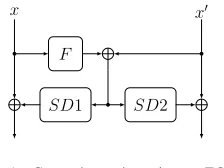
Fig. 1. Correction point using an ECC.
d/2and thus, correct the erroneous codeword. Such a look-up table (e′⊕e·P)7→ he|e′iis called asyndrome decoder.
III. METHODOLOGY A. Definitions
Adversary Model. Borrowed from [1], we define a slightly stronger adversary model. The attacker is able to inject fault att arbitrarily cells (either a register or a gate), which means flipping the output of the cell or setting it to a certain value. As a consequence, every cell driven by faulty cell(s) can be faulty as well.
Definition 5 (Univariate Adversary Model Mt). In a given
sub-circuit, the adversary is able to make up to tcells faulty in the entire operation of the algorithm, e.g., a full encryption.
t can be split into various clock cycles.
Definition 6 (Multivariate Adversary Model M∗
t [1]). Here,
the adversary can target up to tcells at every clock cycle.
Fault Propagation and Independence Property. When the attacker induces fault intcells, more thantfaulty bits can be present at the sub-circuit output due to fault propagation. In other words, anMt-bounded attacker can targettcertain cells
in such a way that more thantfaults appear at the sub-circuit output avoiding the underlying code to detect or correct it. To thwart fault propagation, independence propertyhas been defined in [1]. It means that no cell should be shared between functions which generate different output wires. Hence, by inducing fault in one cell, the fault can only affect one output.
Correction Point. In order to correct a faulty codeword, we use the typical ECC construction shown in Fig. 1. We refer to the application of matrixP onxto derivex′ byF :Fk
27→Fm2
as F(x) =x·P, where m=n−k denotes the redundancy bit-length. As discussed in Section II-A, using an[n, k,2t+1] -code, there exist a syndrome decoder to correct all faults with Hamming weight of at most t. Assume a faulty input hx|x′i
with the injected fault being he|e′i. At the correction point,
the syndrome decoder is fed byF(x)⊕x′; hence, the injected fault heˆ|eˆ′i is predicted. If wt(e) +wt(e′)≤t, the predicted
fault is the same as the injected one. If so, XORing heˆ|eˆ′ito
the input word omits the injected fault. Note that in Figure 1 we split the syndrome decoder to two parts with SD1 and
SD2 predictingˆeandˆe′, respectively.
B. Application
In order to apply our strategy, we consider a general algorithm that is realized by a sequential circuit depicted in Figure 2(a). It consists of a register which loads the INPUT
rst
Input
Output
T
(a) Structure
rst rst
Input
F
F
SD1
T
F
SD2
T′
Output
(b) InjectiveF
Input
F F
SD1
T T′
rst
Output
(c) Non-InjectiveF
Fig. 2. Our construction with respect to application of an ECC.
at the beginning (triggered by rst signal) and performs the function T repeatedly until the OUTPUT is taken from the register. Note that any sequential circuit can be represented by such a construction. For the sake of simplicity suppose that the bit-length of INPUT, register, and input and output of
T is a multiple of k bits. The application of an [n, k]-code would lead to transforming every k-bit chunkx to an n-bit codeword c = hx|x′i. In the following, considering only a
univariate adversary model and also two different cases forF, we explain how the underlying ECC is applied.
Injective F.In this case which necessities the redundancy to be at least as large as the message size (e.g., n ≥ 2k), the redundant part of the circuit can operate onx′independent of x, as shown in Figure 2(b). The redundant function T′ can
also be achieved asT′ =F◦T◦F−1. It is necessary to put a
correction point at the input of each operation. Otherwise, the faults injected at the register cells would potentially propagate to multiple output bits of T /T′. All output bits (dashed
boxes in Figure 2(b)) must be implemented fulfilling the independence property which may necessitate to implement several instances of F, SD1 andSD2. Note that, in a code with distanced= 2t+ 1, the output of SD1does not change if up to t faults are injected at its input. In other words,
SD1 does not propagate faults e with wt(e) < t. Thus, F
and the corresponding XOR can be instantiated separately, while it does not hold for SD2 (see Figure 2(b)). Since the multiplexer and the register operate on each bit of the T
output independently, they fulfill the independence property automatically. Hence, any fault injected onT /T′ fitting to the
adversary model is corrected at the correction point in the next clock cycle.
Non-InjectiveF.Here,T′ needs to receive the original data x to compute T′(x) = F ◦T(x). This means that we only
need to correctx. The corresponding construction is shown in Figure 2(c), where the independence property can be divided in two parts (two dashed boxes). It is indeed the same as the left part of Figure 2(b) with a different T′.
to the diffusion properties of T, implementing T fulfilling the independence property can be area-wise expensive. The area overhead might be reduced by implementing T1 and T2
independently with their corresponding correction points, and fulfilling the independence property for each part. It is worth to mention that the benefit might be marginal since more correction points are required (it depends on the diffusion of
T1 and/or T2).
In several block ciphers including CRAFT [7], Midori [5] and Skinny [6], the linear layer can be represented as a binary matrix over elements ofF2k. It is proven in [1] that such sub-functions do not propagate the injected faults. Hence, they do not need an extra correction point if implemented following the aforementioned decomposition form.
FSM and Control Signals.Finite-State Machine (FSM) is a vital part of the algorithm because the attacker can manipulate the FSM and control the flow to obtain critical outputs, like middle value of the cipher easily exploiting the secrets. Every FSM can be implemented by a set of registers called STATE, initialized by INIT and updated every clock cycle by means of an update function U. The statements given for different constructions depending onF(injective/non-injective) hold for the FSM as well. It should be implemented following Fig 2 replacing T by the update function U and INPUT by INIT. Each functionGi which generates a control signalsi, receives
the corrected STATE, where its redundant counterpart s′
i =
F({0}k−1|s
i). In other words, every single-bit control signal
is padded with zero to form ak-bit chunk; the encoded chunk
s′
i is ofmbits.
• InjectiveF: Here, the redundant part of each control signal is made ass′
i=G′i(STATE′)withG′i=F◦Gi◦F−1. • Non-Injective F: Each control signal si is mapped to
s′
i = G′i(STATE) with G′i = F ◦Gi. Note that, if there
is a G′i(.) satisfying G′i◦F = F ◦Gi, it is possible to
generates′
i over STATE′.
It is noteworthy that implementation of all functions should follow the independence property.
Multiplexer. Suppose a k-bit multiplexer switching between
xandycontrolled by the signals. As stated before, the redun-dant counterpart of s,x, andyarem-bit wide. To apply error correction, the multiplexer is combined with its redundant counterpart to form ak+m-bit multiplexer switching between hx|x′i and hy|y′i by an m+1-bit control signal hs|s′i. The
combined multiplexer should be implemented by a multiplexer tree in m+1 levels. The first row is controlled by the control signal s, and the other rows by the corresponding bit of the redundant control signals′. The inputsv
i∈{0,...,2k+m
−1}of the
first multiplexer row are defined as follows:
vi=
hx|x′i ; i=h0|F(0)i ⊕∆, wt(∆)< d/2 hy|y′i ; i=h1|F(1)i ⊕∆, wt(∆)< d/2
0 ; else
If the functions generating the control signals and their redun-dant part fulfill the independence property, this construction guarantees the correction oft < d/2faulty gates, sincehs|s′i
is a codeword with distance d.
Output.We suppose that the circuit contains a control signal DONE indicating the termination of the computation. To avoid sniffing intermediate results by injecting a fault into such a signal, a construction similar to the multiplexer can be used. To this end,DONEsignal should be protected from faults turning it from ‘0’ to ‘1’. TheDONEsignal is concatenated with itsm-bit redundancy and forms anm+1-bit signal controlling an m+1
levels multiplexer. The final result of the cipher should pass through this multiplexer whose first row inputs are defined as:
vi=
OUTPUT ; i=h1|F(1)i
0 ; else
Considering the independence property, this construction guar-antees to prevent any sniffing witht < dfaults on DONE and its redundancyDONE′.
C. Extension to Multivariate
Suppose the circuits shown in Fig 2 with an[n, k, d]-code, which under the Mt adversary model correct all t faults
when d = 2t+ 1. To protect the circuit against the M∗ t
adversary model, we needd/2to be larger than the maximum number of faults that the adversary can inject between two consecutive correction points. For instance, in the circuits shown in Figure 2, there is only one correction point in each clock cycle; hence, the maximum number of faults that can be injected between two consecutive correction points is 2t. To protect this circuit against theM∗
t adversary model, we need
to embed a code withd= 4t+ 1. It is noteworthy to mention that for circuits which include more than one correction point in one clock cycle, only changing the first correction point to the one using a code withd= 4t+ 1is enough. While other correction points can still use the code withd= 2t+ 1.
IV. CASESTUDY
To evaluate our proposed methodology in terms of overhead as well as fault correction, we investigated the block cipher CRAFT designed with respect to efficient protection against DFA [7]. Our analyses are base on Synopsys Design Compiler with the NanGate 45 nm ASIC standard cell library.
A. Cipher
CRAFT operates on a 64-bit state, 64-bit tweak, and a 128-bit key in 32 rounds. Each round consists of SubBox (SB), MixColumn (MC), PermuteNibbles (PN), AddConstant (AC), and AddTweakey (AT), while SB and PN are not applied in the last round. Based on the given key and tweak, the KeySchedule generates four 64-bit tweakeys, one of which is selected depending on the round counter. After loading the plaintext, MC is applied to each column; then the selected tweakey and RoundConstants are XORed to the state, followed by PN and SB.
B. Implementation Details
We focused on a round-based implementation of CRAFT. Since CRAFT uses a 4-bit S-box, we fixedk= 4in[n, k, d]
2-bit faults, respectively. Thus, we used[7,4,3]-code for 1-bit and[11,4,5]-code for 2-bit corrections in our implementation.
[7,4,3]-code: Here, F(.) cannot be injective; therefore, the architecture shown in Figure 2(c) should be followed by the following generator matrix.
G[7,4,3]=
1 0 0 0 0 1 1
0 1 0 0 1 1 1
0 0 1 0 1 0 1
0 0 0 1 1 1 0
= (I4 | P)
In such cases, the MC, PN, and XORs can operate solely on redundant part of the cipher. For FSM and S-box,F◦UF SM
andF◦S should be implemented respectively.
Optimization. As mentioned in Section III-B, the select signal of the multiplexers is a concatenation of the single-bit sand its redundancy s′. Hence, hs|s′i can be h0|F(0) = 0000i or h1|F(1) = 1111i. The distance of these two codewords is 4 while it is possible to correct single-bit faults with a distance of 3. Thus, by selecting only 3 bits ofhs|s′i(includings), we
can achieve the same goal with less area overhead.
[11,4,5]-code: Since hereF(.)is injective, the structure shown in Figure 2(b) is followed with the following generator matrix.
G[11,4,5]=
1 0 0 0 1 1 1 1 0 0 0
0 1 0 0 1 1 0 0 1 1 0
0 0 1 0 1 0 1 0 1 0 1
0 0 0 1 0 1 0 1 0 1 1
Since the MC matrix consists only of zero and one and as stated in [1], the same MC matrix can be used for the redundant counterpart. The same holds for the PN module, while the redundant part of the S-box is derived byF◦S◦F−1,
as given in Section III-B.
Similar to the data path, all key nibbles are also encoded, so all XORs (AC and AT) are straightforward in the redundant part. The permutation of the tweak is also done trivially due to its nibble-wise structure. Two LFSRs are used in this block cipher to generate RoundConstants. We followed the same implementation styles as in [7] to encode them. The DONE, derived from the LFSR states, is a 7-bit coordinate function, while the redundant counterpart contains seven 14-bit coordinate functions (due to the independence property and the code length n= 4 + 7).
Optimization. The output of syndrome decoders is “don’t-care” for some inputs which helped us to reduce the area overhead. The select signal of the multiplexers (which select the tweakeys) can take h0|F(0) = 00000000i or h1|F(1) =
10001111i. By removing the bits tied to ‘0’, we further
reduced the area while achieving the same level of protection.
Majority Voting. We have also implemented the same design equipped with Majority Voting (MV), where the cipher is instantiated2t+1number of times to correct up totbit faults. To this end, we instantiated the cipher 3 and 5 times, followed by the corresponding voting circuitry. Different approaches can be used to realize the voting module, we employed a variant where the entire 65-bit outputs are compared (64-bit ciphertext concatenated by theDONEsignal). The area and latency of our
TABLE I
AREA ANDLATENCY COMPARISON OFCRAFTIMPLEMENTATIONS,
USINGNANGATE45NMASICLIBRARY.
Plain 1-bit Correction 2-bit Correction
MV [7,4,3] MV [11,4,5]
Area (GE) 1097 4502 5187 7711 21617
Latency (ns) 0.55 1.00 0.87 1.03 1.08
implementations are summarized in Table I. It can be seen that our designs has almost no performance benefits compared to the classical MV variants. However, in the following we show the pitfalls of MV designs and advantages of our constructions with respect to protection against SIFA.
C. Simulation
In order to assess the effectiveness of our construction, we made use of VerFI [3] the open-source fault-diagnostics tool (ver 2 Beta) https://github.com/emsec/VerFI. It receives the NanGate 45 net-list of the circuit and injects (bounded) stuck-at or toggle faults at any cell at desired clock cycles. We examined our CRAFT implementation with [7,4,3]-code (containing 2729 cells) with all possible single-bit toggle faults at a certain clock cycle, i.e.,Mt=1 adversary model. The tool
required a couple of seconds to report the correction of all single-bit fault injections. For our implementation equipped with [11,4,5]-code, we repeated this experiment for two sce-narios: 1) injecting 2-bit faults on all cells at a clock cycle, i.e., Mt=2 adversary model, and 2) injecting 2-bit faults
split in consecutive clock cycles, i.e., M∗
t=1 model. The tool
confirmed the correction of all faults in both scenarios. The design contains 14102 cells, and the bitsliced version of VerFI running on a 30-core machine with two Intel Xeon CPUs finished all fault injections in 41 and 52 minutes in the first and second scenarios respectively.
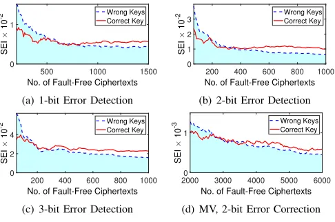
Attacks. We further used the same tool to inject stuck-at faults to emulate SIFA. We first took the CRAFT implementations with fault detection facility [7] (available at https://github.com/ emsec/ImpeccableCircuits/tree/master/CRAFT). We examined 3 versions of such implementations: with 1-, 2-, and 3-bit error detection. Since only fault-free ciphertexts are used in SIFA, recovering the secret is straightforward. We targeted an S-box in the penultimate round with faults fitting into the underlying error detection facility, i.e., 1-bit fault on 1-bit error detection version, etc. We conducted the attack on the collected fault-free ciphertexts by computing the target intermediate value based on a key guess where the correct key guess is identified by the highest Squared Euclidean Imbalance (SEI). The result of the attacks (no. of required fault-free cipheretxts) are shown in Figure 3.
500 1000 1500
No. of Fault-Free Ciphertexts
0 1
SEI
10
-2 Wrong KeysCorrect Key
(a) 1-bit Error Detection
200 400 600 800 1000
No. of Fault-Free Ciphertexts
0 1 2 3
SEI
10
-2 Wrong KeysCorrect Key
(b) 2-bit Error Detection
200 400 600 800 1000
No. of Fault-Free Ciphertexts
0 2 4
SEI
10
-2 Wrong KeysCorrect Key
(c) 3-bit Error Detection
2000 3000 4000 5000 6000
No. of Fault-Free Ciphertexts
0 1
SEI
10
-3 Wrong KeysCorrect Key
(d) MV, 2-bit Error Correction
Fig. 3. Result of SIFA on various protected implementations.
single-bit stuck-at fault was injected on the voting circuit to let the output pass. This reveals whether the first injected fault was ineffective or not. Such information was adequate to successfully mount the SIFA (results in Figure 3). Note that in these cases the injected faults should have been covered by the underlying countermeasure (i.e., 1-bit fault on 1-bit correction, etc.). However, as we examined our constructions with all possible (1-/2-bit) faults exhaustively, no similar attacks is possible on our constructions. The entire HDL codes and analysis scripts used for this paper are available online1.
V. CONCLUSIONS
Sensitive information of any unprotected cryptographic im-plementation can be easily revealed by fault attacks. This necessitates to utilize proper countermeasures. In this work, we demonstrated how to construct circuits which guarantee the correction of faults in two circumstances: 1) when the adversary can inject up totfaults per encryption and 2) when
t faults are injected at every clock cycle. Our constructions cover every component of the design including the data path, FSM, control signals, and even the modules responsible for error correction. As a case study, we applied our methodology on CRAFT block cipher and studied the overhead in terms of area and latency. We further exhaustively evaluated our constructions by VerFI which confirmed the 100% correction of any possible faults fitting into the considered adversary model. Last but not least, we mounted successful SIFA on various designs equipped with fault detection as well as on constructions making use of majority voting. This highlights the advantage of our construction in counteracting such pow-erful attacks that justifies its high area overhead.
REFERENCES
[1] A. Aghaie, A. Moradi, S. Rasoolzadeh, A. R. Shahmirzadi, F. Schellen-berg, and T. Schneider, “Impeccable Circuits,”IEEE Trans. Computers, 2019.
[2] M. Agoyan, J. Dutertre, D. Naccache, B. Robisson, and A. Tria, “When Clocks Fail: On Critical Paths and Clock Faults,” inCARDIS, ser. LNCS, vol. 6035, 2010, pp. 182–193.
[3] V. Arribas, F. Wegener, A. Moradi, and S. Nikova, “Cryptographic Fault Diagnosis using VerFI,” inHOST 2020. IEEE, 2020, https://eprint.iacr. org/2019/1312.
1https://github.com/emsec/ImpeccableCircuitsII
[4] S. Azzi, B. Barras, M. Christofi, and D. Vigilant, “Using Linear Codes as a Fault Countermeasure for Nonlinear Operations: Application to AES and Formal Verification,” J. Cryptographic Engineering, vol. 7, no. 1, pp. 75–85, 2017.
[5] S. Banik, A. Bogdanov, T. Isobe, K. Shibutani, H. Hiwatari, T. Akishita, and F. Regazzoni, “Midori: A Block Cipher for Low Energy,” in
ASIACRYPT, ser. LNCS, vol. 9453. Springer, 2015, pp. 411–436. [6] C. Beierle, J. Jean, S. K¨olbl, G. Leander, A. Moradi, T. Peyrin, Y. Sasaki,
P. Sasdrich, and S. M. Sim, “The SKINNY Family of Block Ciphers and Its Low-Latency Variant MANTIS,” inCRYPTO, ser. LNCS, vol. 9815. Springer, 2016, pp. 123–153.
[7] C. Beierle, G. Leander, A. Moradi, and S. Rasoolzadeh, “CRAFT: lightweight tweakable block cipher with efficient protection against DFA attacks,”IACR ToSC, vol. 2019, no. 1, pp. 5–45, 2019.
[8] G. Bertoni, L. Breveglieri, I. Koren, P. Maistri, and V. Piuri, “Error Analysis and Detection Procedures for a Hardware Implementation of the Advanced Encryption Standard,”IEEE Trans. Computers, vol. 52, no. 4, pp. 492–505, 2003.
[9] E. Biham and A. Shamir, “Differential Fault Analysis of Secret Key Cryptosystems,” inCRYPTO, ser. LNCS, vol. 1294. Springer, 1997, pp. 513–525.
[10] R. E. Blahut,Algebraic Codes for Data Transmission. Cambridge Univ. Press, 2003.
[11] D. Boneh, R. A. DeMillo, and R. J. Lipton, “On the Importance of Checking Cryptographic Protocols for Faults (Extended Abstract),” in
EUROCRYPT, ser. LNCS, vol. 1233. Springer, 1997, pp. 37–51. [12] J. Breier, M. Khairallah, X. Hou, and Y. Liu, “A Countermeasure Against
Statistical Ineffective Fault Analysis,”IACR Cryptology ePrint Archive, vol. 2019, p. 515, 2019.
[13] C. Clavier, “Secret External Encodings Do Not Prevent Transient Fault Analysis,” inCHES, ser. LNCS, vol. 4727. Springer, 2007, pp. 181-194. [14] J. Daemen, C. Dobraunig, M. Eichlseder, H. Groß, F. Mendel, and R. Primas, “Protecting against Statistical Ineffective Fault Attacks,”
IACR Cryptology ePrint Archive, vol. 2019, p. 536, 2019.
[15] C. Dobraunig, M. Eichlseder, T. Korak, S. Mangard, F. Mendel, and R. Primas, “SIFA: exploiting ineffective fault inductions on symmetric cryptography,”IACR TCHES, vol. 2018, no. 3, pp. 547–572, 2018. [16] T. Fuhr, ´E. Jaulmes, V. Lomn´e, and A. Thillard, “Fault Attacks on AES
with Faulty Ciphertexts Only,” inFDTC, 2013, pp. 108–118. [17] Y. Ishai, M. Prabhakaran, A. Sahai, and D. Wagner, “Private Circuits II:
Keeping Secrets in Tamperable Circuits,” inEUROCRYPT, ser. LNCS, vol. 4004. Springer, 2006, pp. 308–327.
[18] R. Karri, K. Wu, P. Mishra, and Y. Kim, “Concurrent Error Detection Schemes for Fault-Based Side-Channel Cryptanalysis of Symmetric Block Ciphers,”IEEE Trans. on CAD of Integrated Circuits and Systems, vol. 21, no. 12, pp. 1509–1517, 2002.
[19] Y. Li, K. Sakiyama, S. Gomisawa, T. Fukunaga, J. Takahashi, and K. Ohta, “Fault Sensitivity Analysis,” inCHES, ser. LNCS, vol. 6225. Springer, 2010, pp. 320–334.
[20] F. J. MacWilliams and N. J. A. Sloane,The Theory of Error Correcting Codes, ser. North-Holland Mathematical Library. North-Holland Pub. Co. New York, 1977.
[21] T. Malkin, F. Standaert, and M. Yung, “A Comparative Cost/Security Analysis of Fault Attack Countermeasures,” inFDTC, ser. LNCS, vol. 4236. Springer, 2006, pp. 159–172.
[22] J. Quisquater and D. Samyde, “Electromagnetic analysis (EMA): mea-sures and counter-meamea-sures for smart cards,” inE-smart 2001, 2001, pp. 200–210.
[23] S. Saha, D. Jap, D. B. Roy, A. Chakraborti, S. Bhasin, and D. Mukhopad-hyay, “Transform-and-Encode: A Countermeasure Framework for Sta-tistical Ineffective Fault Attacks on Block Ciphers,” IACR Cryptology ePrint Archive, vol. 2019, p. 545, 2019.
[24] A. Satoh, T. Sugawara, N. Homma, and T. Aoki, “High-Performance Concurrent Error Detection Scheme for AES Hardware,” inCHES, ser. LNCS, vol. 5154. Springer, 2008, pp. 100–112.
[25] O. Seker, A. Fernandez-Rubio, T. Eisenbarth, and R. Steinwandt, “Extending Glitch-Free Multiparty Protocols to Resist Fault Injection Attacks,”IACR TCHES, vol. 2018, no. 3, pp. 394–430, 2018. [26] N. Selmane, S. Guilley, and J. Danger, “Practical Setup Time Violation
Attacks on AES,” inEDCC-7, 2008, pp. 91–96.