197 |
P a g e
DYNAMIC CHARACTERSTIC ESTIMATION OF
STRUCTURAL MATERIALS BY MODAL ANALYSIS
USING ANSYS
Syed Ayesha Yasmeen
1, Anatha Abhijit P
2, Dr.D.Srinivasa Rao
31, 2
Graduate Students,
3Professor, Department of Mechanical Engineering,
DMS SVH College of Engineering, Machilipatnam, (India)
ABSTRACT
Dynamic properties of a structural element which are frequency, damping and mode shapes can be described by a process called modal analysis Structural condition can be monitored by analyzing the changes in frequencies and mode shapes. All materials posses certain amount of internal damping, which manifested as dissipation of energy from the system. This energy in a vibratory system is either dissipated into heat or radiated away from the system. Material damping or internal damping contributes to about 10-15% of total system damping. The main objective of this work is to estimate the natural frequency and damping ratio of cantilever beams of Aluminum, Brass, and Steel and Acrylic glass by free vibration analysis and Harmonic analysis using ANSYS. This paper presents results of modal analysis of beams made of assorted materials mentioned by generating models using ANSYS which facilitates to save time and cost. Free vibration analysis was carried out for identifying the natural frequencies and the harmonic analysis was carried out for obtaining frequency response curves from which damping ratios were estimated using Half- power Band Width Method. The results were analyzed.
Keywords: Damping Factor, Free Vibration, Harmonic Analysis, Modal Analysis, Natural
Frequency
I INTRODUCTION
Modal analysis is an effective means for identifying, accepting and simulating dynamic behavior and responses
of structural elements. Modal analysis using ANSYS is an effective method of determining vibration
characteristics. In the present cram the finite element package program was used to model the physical system
and to simulate close to its real condition. Simulation enables us to save time and cost. Practical applications of
modal analysis cross over assorted fields of science engineering and technology, in particular various
explorations connected to automobile engineering, aeronautical engineering and mechanical engineering. The
present exploration reports the dynamic characteristics of common structural materials.
Material damping of cantilever beams attracts a lot of work even though extensive literature exists in the area of
vibrations of beams. Material damping has not been paid much attention. Vibration characteristics of rotating
198 |
P a g e
H H Yoo and S H Shin[1]. The centrifugal inertia force due to rotation induces stretching and this stretchingcauses increase of bending stiffness of the structure which generally results in the variation of natural
frequencies and mode shapes. A new dynamic modeling method is adopted for deriving the equation of motion
of rotating cantilever beams.
Mousa ReZaee and reZa Hassannejad[2] investigated a simply supported beam with a crack by vibration
analysis and derived a new analytical method by taking a non-linear model for fatigue crack perturbation
method is used for solving the governing equation of motion of the cracked beam. The dynamic response of
cracked beam shows super harmonics of fundamental frequency due to non-linear effects in the solution. An
explicit expression is also derived for the system damping changes in the crack parameters geometric
dimensions, Mechanical properties of the cracked beam. It is observed in the results the system damping
increases with crack depth and its approach to the middle of the beam. The frequencies of free vibration of
rotating beams have been extensively studied by Chih Ling Huang, Wen Yi Lin, Kuo Mo Hsio[3] generally
rotating beams are used for simple models such as propellers, turbine blades and satellite booms. To solve the
natural frequency of very slanderous rotating beam at high angular velocity. A method based on the power
series solution is used. Each segment governing equations are solved by power series.
JinsuoNie,XingWei[4] concentrated in determining convenient specification of material dependent damping in
ANSYS in transient dynamic analysis by mode superposition method. In analysis of complex structures
specification of material dependent damping is generally desirable. Since the structural elements can have
different energy dissipation capabilities. This paper contains various mode superposition transient dynamic
analysis using different ways to specify damping in ANSYS. Shibabrat Naik, Wrik Mallik[5] in their study
found substantial importance of dynamic parameters such as modal frequencies and damping constant of
structural elements. In their work experimental model testing of cantilever beam has been performed to obtain
the mode shapes, modal frequencies and damping parameters. PLUSE lab shop was used to get the frequency
response functions and these are checked using finite element software ANSYS.
D. Ravi Prasad [6] in his study explained natural characteristics of a structure like frequency damping and mode
shapes. In his work modal analysis of beams was carried out for different beam materials by excitation
technique and the response functions were obtain and processed using vibration analysis analyzer to identify
natural frequencies, damping and mode shapes. In the present cram the vibration analysis was carries out using
ANSYS by model analysis to find natural frequencies and damping factors of various structural materials.
II THEORTICAL ANALYSIS
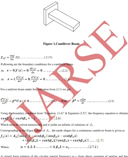
2.1. Theory of Free Vibrations of Cantilever Beam
The equation of a motion of a cantilever beam subjected to free vibration, the system of which is considered as
continuous one can be written as
199 |
P a g e
Where, E is the modulus of rigidity of beam material, I is the moment of inertia of the beam cross- section y(x)is displacement in y direction at distance x from fixed end, is the circular natural frequency, m is the mass
per unit length, m=ρA(x), ρ is the material density, x is the distance measured from the fixed end.
……… (.2.13)
Following are the boundary conditions for a cantilever beam.
At , (2.2)
At .. (2.3)
For a uniform beam under free vibration from (2.1) we get
(2.4) With (2.5)
Using the boundary condition from “Equation. (3.4)” & Equation (3.5)”, the frequency equation is obtained as
Which must be solved numerically and it yields an infinite of solutions of .
Corresponding to the Eigen values of , the mode shapes for a continuous cantilever beam is given as
Where,
A closed form solution of the circular natural frequency from above equation of motion and boundary
conditions can be written as, )
The equation (2.8) is satisfied by a number of values of corresponding to each normal mode of oscillation,
which for first three modes are given as
200 |
P a g e
Where, First natural frequency
……… (2.10)
Second natural frequency
………. (2.11)
Third natural frequency
………. (2.12)
The natural frequency is related with the circular natural frequency as
2.2. Measurement of Damping
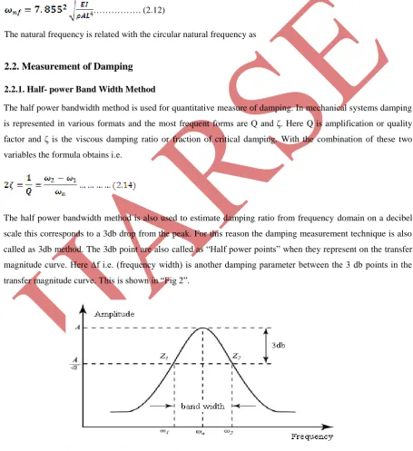
2.2.1. Half- power Band Width Method
The half power bandwidth method is used for quantitative measure of damping. In mechanical systems damping
is represented in various formats and the most frequent forms are Q and ζ. Here Q is amplification or quality
factor and ζ is the viscous damping ratio or fraction of critical damping. With the combination of these two
variables the formula obtains i.e.
The half power bandwidth method is also used to estimate damping ratio from frequency domain on a decibel
scale this corresponds to a 3db drop from the peak. For this reason the damping measurement technique is also
called as 3db method. The 3db point are also called as “Half power points” when they represent on the transfer
magnitude curve. Here ∆f i.e. (frequency width) is another damping parameter between the 3 db points in the transfer magnitude curve. This is shown in “Fig 2”.
201 |
P a g e
III MODAL ANALYSIS
Modal analysis is a universal methodology used which permit fast and reliable recognition of system dynamics
in complex structures. In the previous decades numerous methods have been developed in expedition to develop
accuracy of modal replicas extracted from test data and to expand the applicability of modal analysis in
manufacturing environment.
Structures vibrate in special shapes called mode shapes when excited at their resonant frequencies. A mode
shape is the typical deformation contour defined by relative amplitudes of the farthest locations of vibration of a
system at a particular natural frequency. The modal parameters are the natural frequencies, damping ratios and
modal masses connected with each of the mode shapes. In general working circumstances, the structure will
vibrate in a complex combination of all the mode shapes. Modal analysis refers to evaluating and forecasting the
mode shapes and frequencies of a structure.
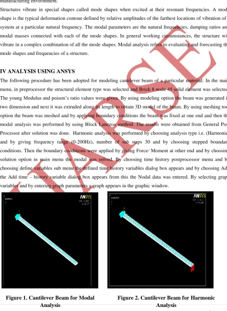
IV ANALYSIS USING ANSYS
The following procedure has been adopted for modeling cantilever beam of a particular material. In the main
menu, in preprocessor the structural element type was selected and Brick 8 node 45 solid element was selected.
The young Modulus and poison‟s ratio values were given. By using modeling option the beam was generated in
two dimension and next it was extruded along its length to obtain 3D model of the beam. By using meshing tool
option the beam was meshed and by applying boundary conditions the beam was fixed at one end and then the
modal analysis was performed by using Block Lanczos method. The results were obtained from General Post
Processor after solution was done. Harmonic analysis was performed by choosing analysis type i.e. (Harmonic)
and by giving frequency range (0-200Hz), number of sub steps 30 and by choosing stepped boundary
conditions. Then the boundary conditions were applied by giving Force/ Moment at other end and by choosing
solution option in main menu the modal was solved. By choosing time history postprocessor menu and by
choosing define variables sub menu the defined time history variables dialog box appears and by choosing Add
the Add time – history variable dialog box appears from this the Nodal data was entered. By selecting graph
variables and by entering graph parameters a graph appears in the graphic window.
Figure 1. Cantilever Beam for Modal
Analysis
202 |
P a g e
V RESULTS AND DISCUSSION
The objective of the present work is to compare the natural frequencies and damping of different structural
materials like Brass, Aluminum, Mild Steel and Acrylic glass materials. The observations have
been taken to
calculate
damping factor for various materials mentioned above by taking common dimensions of theCantilever Beam in the frequency range of (0 to 200 Hz).
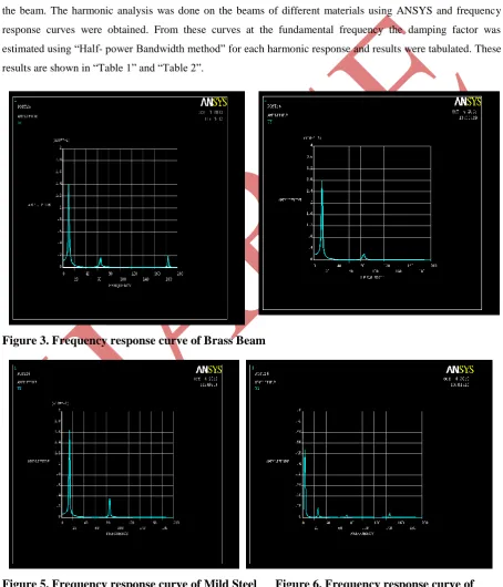
The first five natural frequencies were calculated by Modal Analysis using ANSYS by generating the modal of
the beam. The harmonic analysis was done on the beams of different materials using ANSYS and frequency
response curves were obtained. From these curves at the fundamental frequency the damping factor was
estimated using “Half- power Bandwidth method” for each harmonic response and results were tabulated. These
results are shown in “Table 1” and “Table 2”.
Figure 3. Frequency response curve of Brass Beam
Figure 5. Frequency response curve of Mild Steel Figure 6. Frequency response curve of
203 |
P a g e
Table 1. Comparison of Theoretical and ANSYS Natural Frequencies
Table 2. Indication of damping Factors of Materials Considered
S.No Material
Beam dimensions(mm)
Damping
Factor
(ζ)
01
Brass
600x25.4x6
0.163
02
Aluminum
600x25.4x6
0.288
03
Mild Steel
600x25.4x6
0.344
04
Acrylic
600x25.4x6
0.464
It is found that the Natural Frequency of Aluminum and Mild Steel are more than Brass and that of Acrylic
beam is very low. This implies that the stiffness in turn the Young‟s Modulus of Aluminum and Mild Steel are
more compared to Brass and the stiffness of Acrylic glass material are very low.
It is evident that the material damping is higher for Acrylic material and mild steel beams when compared to
Aluminum and Brass for the adopted dimensions of the beam. It was observed during iterations that the
damping ratio depends on the dimensions of the beam. Hence the modal analysis is plays a major role in
evaluating the vibration parameters like natural frequencies and structural damping factors. The results obtained
are well corroborated with theoretical values.
VI CONCLUSION
The main objective of the present work is to study the vibration damping characteristics of four structural
Materials i.e. Acrylic, Steel, Aluminum and Brass. The cantilever beams have been subjected to free vibration
and Harmonic Analysis using ANSYS and damping ratio has been computed using „Half power Band Width
Method‟.
On the basis of present study the following conclusions are drawn. It is a nondestructive testing strategy based
on model generation. From the Analysis it is evident that material damping is higher for Acrylic and steel in
comparison with Brass and Aluminum beams of same dimensions.
The increase in material damping could be correlated to the stiffness of materials.
The damping of specimen made up of Brass was found to be lowest than Acrylic, Steel and Aluminum.
Material
Frequency by
Theoretical method
Frequency
using ANSYS
% error
Brass
10.323
10.461
1.33
Aluminum
13.607
13.797
1.39
Mild Steel
13.588
13.776
1.38
204 |
P a g e
The theoretical result obtained by the method proposed in this work and ANSYS results of vibration are infair matching in terms of natural frequency.
The model testing using ANSYS has been proven to be an efficient and non-destructive method for estimation
of dynamic characteristics like damping factors and natural frequencies.
REFERENCES
[1] H H Yoo and S H Shin, Vibration analysis of rotating cantilever beams, Journal of Sound & Vibration,
Pages 807-828, 12 Dec.1997.
[2] Mousa ReZaee and reZa Hassannejad Damped free vibration analysis of a beam with a fatigue crack using
energy balance methods, International Journal of the Physical Sciences, Pages 793-803, Volume 5(6), June,
2010.
[3] Chih Ling Huang, Wen Yi Lin, Kuo Mo Hsio Free vibration analysis of rotating euler
beams and high angular velocity, Deptt. Of Mechanical Engineering; National Chiao Tung University, Hsinchu
Tiawan 14 Nov. 2005.
[4] JinsuoNie,XingWei On the use of material-dependent damping in ANSYS for made superposition of
transient analysis, Proceedings of the ASME-2011 pressure vessels and piping division; Broakhaven National
Laboratory, July,2011.
[5] Shibabrat Naik, Wrik Mallik Experimental modal testing for estimating the dynamic properties of a
cantilever beam, Structural Dynamics.
[6] D. Ravi Prasad A study on dynamic characteristics of structural materials using modal analysis , Asian
Journal of Civil Engineering, Volume 9, Number 2, Pages 141-152, 2008.
7] ANSYS Release 10.0, ANSYS Inc.2010