A Framework for Intelligent Spectrum Sharing
Felipe A. P. de Figueiredo, Xianjun Jiao, Wei Liu, Irfan Jabandži´c, Spilios Giannoulis, and Ingrid Moerman
Ghent University - imec, IDLab, Department of Information Technology, Ghent, BelgiumEmail: [felipe.pereira, xianjun.jiao, wei.liu, irfan.jabandzic, spilios.giannoulis, ingrid.moerman]@ugent.be
Abstract— The explosive emergence of wireless technologies and standards, covering licensed and unlicensed spectrum bands has triggered the appearance of a huge amount of wireless technologies, with many of them coexisting in the same band. Unfortunately, the wireless spectrum is a scarce resource, and the available frequency bands will not scale with the foreseen demand for new capacity. Certain parts of the spectrum, in particular the license-free ISM bands, are overcrowded, while other parts, mostly licensed bands, may be significantly underutilized. As such, there is a need to introduce more advanced techniques to access and share the wireless medium, either to improve the coordination within a given band, or to explore the possibilities of intelligently using unused spectrum in underutilized (licensed) bands. Therefore, in this paper, we present a SDR based framework that can be employed to devise disruptive techniques to optimize the sub-optimal use of radio spectrum that exists today. Additionally, we describe two use cases for the proposed framework.
Index Terms— Intelligent Radio Networks; Spectrum Sharing; Coexistence; Experimental Evaluation.
I. INTRODUCTION
Most of today’s channel allocations separate wireless sys-tems by splitting the spectrum into fixed and exclusively licensed bands that are assigned over large and geographically defined regions. This approach restricts access to the spectrum in exchange for guaranteed interference-free communications. These allocations of spectrum are human-driven and not adaptive to the dynamics of the traffic demand and supply. At any given time, many allocated spectrum bands are unused by their licensees while other bands are completely flooded. For example, a report from the Federal Communications Commission’s (FCC) Spectrum Policy Task Force (SPTF) shows that 85% of current allocated radio frequency bands are either partially or completely unused at different times across geographical areas [1]. This kind of channel allocation scheme wastes the tremendous spectrum capacity and creates unnecessary scarcity [2].
Spectrum sharing, where more than one user shares the spectrum band, either in time and/or space, is one possible and highly viable approach to achieve better spectrum uti-lization (i.e., combat spectrum bandwidth scarcity) and meet the foreseen increase in traffic demand. Access to shared and unlicensed spectrum bands will be of huge importance to next generation wireless networks as they have the potential to provide significant gains, both in terms of spectrum effi-ciencies that translate to higher data speeds for the users and enabling new capabilities such as guaranteed bandwidth and new deployment scenarios [3].
Technologies such as Unlicensed (U), LTE-Licensed Assisted Access (LTE-LAA) and MulteFire, oper-ating in unlicensed or licensed shared spectrum bands avoid interfering with neighbours using simple sense-and-avoid tech-niques, however, in the foreseen dense and diverse future use of spectrum, these simple schemes will not survive, because only local information about the medium availability is insuf-ficient to maintain end-to-end Quality-of-Services (QoS) of multiple competing wireless links. In order to reap the full capacity out of available spectrum bands, technologies for next generation wireless networks need to forget about these simple avoidance and isolation techniques. Next generation radios have to abandon the safety provided by frequency isolation, i.e., fixed channel allocations, and employ greater intelligence to avoid interference while maximizing spectrum usage and capacity. These radios will need to collaborate with their peers in order to attain stable and adequate communications for all involved radios [4].
Radios for next generation wireless networks have to be devised not only to communicate reliably in congested and contested environments but also to share radio spectrum with-out direct coordination or spectrum pre-allocation planning across a wide range of heterogeneous radios. Researchers need to rethink the strategies for spectrum access and develop new wireless paradigms where radio networks can autonomously collaborate, understand the current state of the spectrum, and reason how to share the spectrum bandwidth, avoid causing and being interfered with, and jointly exploit opportunities to attain the optimum usage efficiency of the available spectrum bandwidth.
Therefore, unlicensed and licensed based spectrum sharing models will encourage the research and development of novel concepts, covering a wide range of topics, including the appli-cation of machine learning (ML) and artificial intelligence (AI) algorithms and models to the problem, deployment models, spectrum/regulatory, radio access design, support of standalone mode, network architectures, ecosystems and business models to fully and intelligently increase the spectrum usage efficiency and enhance coexistence [5].
In recent years, prototyping and experimental validation of innovative wireless technologies has gained an increased importance due to the ever increasing complexity of the wireless ecosystem in the emerging next generation wireless networks scenarios. Testbeds play a major role in developing and testing new wireless communications technologies and systems and as with any disruptive technology, prototyping using realistic testbeds is the best way to truly understand
the performance trade-offs. Based on that, several research initiatives are proposing the design of modifiable prototyp-ing frameworks and platforms for evaluatprototyp-ing, comparprototyp-ing and validating the performance trade-offs of innovative wireless devices, communication techniques, network models, services, etc. in realistic testbed environments.
Software Defined Radios (SDRs) [6] are radio communica-tion systems where transceiver components that are typically implemented in hardware (e.g., filters, modulators, demodu-lators, etc.) are instead implemented in software on a per-sonal computer or embedded system. SDR platforms provide flexibility in reconfiguration of baseband algorithms, software and reprogramming of Radio Frequency (RF) parameters. Moreover, the concept of SDR is very encouraging for the development of novel wireless communications technologies, as software programming allows much faster development cycles and real-life experiments to be conducted for example at local or remote testbeds.
In order to ensure that the next generation of wireless networks can get the most out of collaborative and intelligent spectrum sharing techniques in real-world environments, we present in this paper an open source and runtime configurable SDR based framework which is relevant for experimental research and prototype development of novel spectrum shar-ing and coexistence mechanisms in realistic environments [7]. The framework is composed of three main modules, namely, packet-based physical (PHY) layer, spectrum sensing and multiple-access channel-sharing modules. The proposed framework is implemented using USRP Hardware Driver (UHD) software Application Programming Interface (API) [8] and runs on commercially available off-the-shelf (COTS) hard-ware devices such as the Universal Softhard-ware Radio Peripheral (USRP) [9], which is a platform for SDR development.
II. PROPOSEDFRAMEWORK
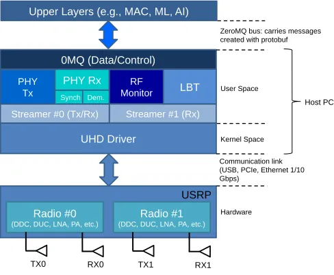
In this section the proposed framework is described in details. It is comprised of three main modules: (i) slot-based PHY layer (for discontinuous data transmission and reception), (ii) RF Monitor (for spectrum sensing purposes) and (iii) Listen Before Talking (LBT) (for Radio Access Technology (RAT) coexistence). All the main modules are connected to the ZeroMQ (Data/Control) module, which interconnects the framework with upper layers through the ZeroMQ bus [10]. This module manages the exchange of control and statistics messages between the framework and upper layers. The framework is used in conjunction with Ettus USRP family of devices including PXIe platforms [8] and communicates with it through the UHD driver [9]. The high level architecture of the proposed framework is summarized in Figure 1.
USRP devices are hardware platforms developed for soft-ware defined radio (SDR), and are commonly used by research labs, universities, and hobbyists. USRP devices are controlled through the UHD driver. The driver provides an Application Programming Interfaces (API) that enables controlling and accessing all features provided by USRP devices, while ab-stracting the low level implementation details of the hardware.
Proposed Framework Architecture
UHD Driver
USRP Radio #0
(DDC, DUC, LNA, PA, etc.)
Radio #1 (DDC, DUC, LNA, PA, etc.)
TX0 RX0 TX1 RX1
Streamer #1 (Rx) Streamer #0 (Tx/Rx)
RF Monitor 0MQ (Data/Control) Upper Layers (e.g., MAC, ML, AI)
Communication link (USB, PCIe, Ethernet 1/10 Gbps)
ZeroMQ bus: carries messages created with protobuf
Kernel Space
Hardware User Space
Host PC
LBT PHY
Tx
PHY Rx Synch Dem.
Fig. 1. Proposed Framework Architecture.
The most important operations provided by the UHD driver fall into two classes, namely, control and streaming. Control operations are used to set frequency, sample rate, gain, etc. of the radios. Streaming operations are carried out through streamer objects, which allow applications running on the host to connect to Tx and Rx sample streamers offered by the USRP device. These samples come from the radios available in the devices. An Rx streamer object allows applications to receive samples from the device and a Tx streamer object allows applications to transmit samples to the device [9].
The slot-based PHY exclusively uses Streamer #0, both Tx and Rx sample streams, and is fed by Radio #0. The RF Monitor and LBT modules share Streamer #1 (both of them only use the Rx sample stream), which is fed by Radio #1. For performance reasons, each one of the modules, ZeroMQ Data/Control processing, PHY Tx, PHY Rx Synchronization, PHY Rx Data Demodulation, RF Monitor and LBT runs on an exclusive thread.
for intelligent spectrum sharing experimentations towards next generation of wireless networks.
Through the use of the proposed framework, a myriad of real-world experiments can be performed, ranging from research of new physical layer techniques (e.g., higher or-der modulation schemes, novel waveforms and numerologies, channel coders, etc.) to RAT coexistence in unlicensed and licensed shared spectrum bands (e.g., comparison of the fairness between different contention-based mechanisms such as Carrier Sense Adaptive Transmission (CSAT) and LBT, impact of different parameters such as Channel Occupancy Time (COT), idle time, Tx power, PHY bandwidth, spectrum overlap, MCS on the performance of Wi-Fi and LTE networks, etc.) to collaborative and intelligent radio networks (i.e., networks where AI and ML components act as the brain of the system and control various aspects of medium access and PHY layers to ensure adaptability, while also running some sort of collaboration protocol [12, 13]).
In the next sections, we describe each one of the main modules present in the proposed framework.
III. SLOT-BASEDPHYSICALLAYER
In spectrum sharing scenarios, several users might share the medium at the same time and continuous access to it might not be possible all the time. With discontinuous transmissions, it is possible to have a better use of the available spectrum band and opportunistically/intelligently/collaboratively coordi-nate its usage with other networks. Additionally, continuous access is not preferable for the sake of fair medium sharing as it is more aligned with systems operating in licensed bands where there is no need for sharing. Moreover, in unlicensed spectrum, some regulatory authorities do not allow continuous transmissions and limit the maximum duration of a transmis-sion burst [14].
A PHY layer presenting a discontinuous transmission fea-ture would have a great value to spectrum sharing research, as it could be used to leverage techniques devised to achieve fairer coexistence and higher spectral efficiency in scenarios where time-frequency resources are shared. Therefore, as part of our framework for spectrum sharing research, we decided to develop a discontinuous transmission-based PHY, which transmits data bursts in small transport units called slots. A slot is the container through which data is exchanged in the network.
The LTE PHY layer standard is the starting point for the development of the proposed slot-based PHY. We decided to base the development on LTE PHY standard as it offers several advanced features including high spectrum efficiency, multiple bandwidths, high peak data rates, mobility, multi-user access, flexible time framing and time-frequency structure, link adaptation with adaptive modulation and coding schemes and multiple-input and multiple-output (MIMO) [15, 16]. Moreover, the next generation of wireless networks (i.e., 5G) will initially evolve from LTE standards [15], i.e., they will be made available through improvements in LTE, LTE-Advanced and LTE Pro technologies [17]. The proposed
slot-based PHY is built upon the srsLTE open-source library [18], and therefore, absorbs and evolves on top of the existing LTE features.
In order to stay aligned with both LTE standards and 5G initiatives [16, 17], we decided to adopt an Orthogonal Frequency-Division Multiplexing (OFDM) based waveform. OFDM is a mature technology, which is vastly implemented in a great number of products due to its several advantages such as robustness to severe multipath fading, low imple-mentation complexity, easy integration with MIMO, simple channel estimation, etc. [16]. Additionally, OFDM allows for enhancements such as waveform windowing/filtering, which can effectively minimize out-of-band spurious emissions [19]. It is also worth mentioning, that compared to other popular OFDM-based technologies like Wi-Fi [20] and Digital Video Broadcasting-Terrestrial (DVB-T) [21], LTE was devised since its inception for multi-user communications by assigning sub-sets of 12 subcarriers (also known as a resource block (RB)) over multiple 1 ms long subframes to individual users. This flavor of multiple access is known as Orthogonal Frequency-Division Multiple Access (OFDMA) and gives LTE a very flexible way of allocating time/frequency resources to multiple concurrent users.
As mentioned earlier, the proposed slot-based PHY module is split into three submodules, namely, PHY Tx, PHY Rx Synchronization and PHY Rx Demodulation where each one of them runs on an exclusive thread. PHY Tx thread is responsible for modulation and transmission of data (i.e., user and control data). PHY Rx Synchronization thread is responsible for the Primary and Secondary Synchronization Signal (PSS/SSS) detection, Carrier Frequency Offset (CFO) correction and slot alignment tasks. PHY Rx Demodulation thread takes care of user and control data demodulation. The slot-based PHY receives data and control messages from the ZeroMQ Data/Control thread.
Regarding numerology, the proposed PHY supports LTE numerology with the same subcarrier spacing (15 kHz) and the cyclic prefix (CP) lengths (normal and extended CPs). However, the proposed PHY also supports the configuration of different (larger and smaller) subcarrier spacings and CP lengths by adopting different sampling rates. Larger subcarrier spacing is used to mitigate inter-carrier interference (ICI) at high frequency bands and smaller spacing allows for extended coverage (due to increased Power Spectral Density (PSD)) and high delay spread scenarios (due to longer CP) at low frequency bands [16, 17].
Different CP lengths are used to accommodate different lev-els of inter-symbol interference (ISI) at different frequencies, coverage and mobility [17]. All LTE predefined bandwidths (1.4, 3, 5, 10, 15 and 20 MHz) are supported. PHY channel bandwidth (BW) can be changed through command line at start up, or in real-time, through one of the control messages, which are introduced later in this section.
Time Frequency
0 1 2 3 4 5 6 7 8 9 10 11 12 13
su
b
ca
rr
ie
rs
OFDM Symbols 1 Slot = 1 ms Slot type #1: equivalent to subframe #0
Time Frequency
0 1 2 3 4 5 6 7 8 9 10 11 12 13
su
bc
a
rr
ie
rs
OFDM Symbols 1 Slot = 1 ms Slot type #2: equivalent to subframe #5
Time Frequency
0 1 2 3 4 5 6 7 8 9 10 11 12 13
su
bc
a
rr
ie
rs
OFDM Symbols 1 Slot = 1 ms
Slot type #3: equivalent to subframes other than #0 and #5
RS Available for PDSCH (user data)
SSS PSS
PBCH PCFICH, PDCCH, PHICH
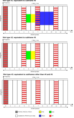
Fig. 2. Proposed slot types for normal CP length.
slot is the basic transmission unit of the proposed PHY and each one is 1 ms long. Depending on its type, a slot might carry synchronization signals, reference signals, broadcast, control and user data.
Three different types of slots following the same definition as the LTE subframes are proposed [15, 16]. The first type, which is equivalent to subframe #0 in the LTE standard, carries synchronization signals (PSS/SSS), reference signals, broadcast, user and control data. The second type is equivalent to LTE’s subframe #5 and carries synchronization signals (PSS/SSS), reference signals, user and control data. The third type, which is equivalent to LTE’s subframes other than 0 and 5 (i.e., 1 to 4 or 6 to 9), only carries reference signals, user and control data. It is important to notice that the RBs intended to carry user data can be split into different sections and allocated to different concurrent users. All slots types carry user data, signals for channel estimation/equalization, and control data, which holds information on how to decode each one of the possible user data sections. The first two slot types are used for
transmission detection once they carry synchronization signals. The first slot one is used whenever there is a need to transmit broadcast information. As it does not carry synchronization signals, the third type can only be used if it is transmitted after one of the other two types. Similarly to an LTE subframe, each slot can have 14 or 12 OFDM symbols depending on the configured CP length, i.e., normal or extended CP [15]. All the slot types for normal CP are depicted in Figure 2.
The proposed PHY allows bursty transmissions with vari-able COT, i.e., the number of slots to be transmitted in a row without any gap (i.e., idle time) between them is variable. The number of slots in a COT, i.e., frame, is derived based on Modulation Code Scheme (MCS), number of Resource Blocks (RB) and data length (i.e., number of bits to be transmitted) parameters sent by upper layers in the control messages. The minimum COT is equal to 1 ms and is equivalent to a slot. Variable COT enables the support of different traffic loads. Every slot can carry a pre-defined number of bits, which is based on the MCS and number of RBs used for a transmission [16].
The proposed slot-based PHY can operate with two dif-ferent data transmission modes. The first mode can be used to establish communications with multiple nodes in ad-hoc or mesh networks, depending on routing capabilities imple-mented in the upper layers connected to the slot-based PHY (i.e., routing at layer 3 of the OSI model). This mode is a simplification of the LTE channel’s structure and only uses the Physical Downlink Shared Channel (PDSCH) for user data transmissions in both directions, i.e., downlink and uplink, in order to take advantage of both multi-user communications and high performance Forward Error Correction (FEC) provided by turbo codes [16]. Additionally, this mode also uses Physical Control Format Indicator Channel (PCFICH) and Physical Downlink Control Channel (PDCCH) for control purposes and Cell-specific Reference Signals (CRS) for channel estimation and equalization. The second mode operates exactly with the same channel’s structure as adopted in the LTE standard, i.e., it has all downlink and uplink physical layer channels as defined in the standard. This mode can be used to establish communications in a cellular mobile network. In both modes, OFDMA can be used to communicate with multiple users at the same time.
Standard LTE vs. Proposed Frame Structures
. . .
. . .
Subframe #0 Subframe #1 Subframe #5 Subframe #9
Standard LTE Frame Structure
Proposed Frame Structures
. . .
. . .
Frame N-1 Frame N Frame N+1
Slot #0 Slot #1 Slot #M-1
. . .
Slot #0 Slot #1 Slot #M-1
. . .
1) Add PSS/SSS to all slots.
2) Add PSS/SS to first slot only.
Primary Synchronization Channel (PSCH) Secondary Synchronization
Channel (SSCH) Physical Broadcast Channel
(PBCH)
Legend
*M depends on # RBs, MCS and data length.
Advantages
• Data transfer does not need to start at subframe boundaries (bursty transmissions). • Does not use reservation signal, which reduces radio resources utilization efficiency. • eNodeB does not need to inform Channel Occupancy Time (COT)
• Might provide better synchronization and less subframe losses. Variable COT (or frame) with M slots*
Variable COT (or frame) with M slots*
Fig. 3. Standard LTE versus Proposed Frame Structures.
of a COT. This structure increases the number of subcarriers useful for user data transmission (making it possible to reach the highest MCS value, i.e., 28 [22]) and decreases the time to receive and decode slots, consequently improving the throughput. However, this frame structure requires a more complex tracking/synchronization algorithm and the necessity to add information about the number of slots in a COT to the first slot, which means, if the first slot is lost none of the subsequent slots can be decoded.
The first proposed frame structure is more robust to time and frequency fluctuations and should be used in cases where transmitter and receiver nodes are moving as it provides better synchronization and less slot losses. On the other hand, the second frame structure should be used for static or quasi-static nodes. The proposed PHY allows switching between the two frame structures either through command line at initialization or during run-time in order to adapt itself to different radio link conditions. Figure 3 depicts the two types of frame structures supported by the proposed PHY.
The Payload Data Unit (PDU) adopted by the proposed PHY is a Transport Block (TB), which is a concept reused from LTE PHY layer. Therefore, a TB is the payload coming from upper layers and given to PHY to be transmitted over the air through the PDSCH. A TB is defined in the LTE standard and varies according to some parameters [23]. According to the LTE standard, 1 TB consists of a number of bits that can be accommodated within a 1 ms long subframe given the selected number of RBs and MCS [23]. Therefore, given the number of allocated RBs and the desired MCS, upper layers can find the number of bits that can be handled by an 1 ms long slot. The communication between upper layers, e.g., Medium Access Control (MAC), and the proposed PHY layer is carried out through the exchange of four messages. The first two, namely, Tx and Rx Control messages, are used to manage slot transmission and reception respectively. The parameters carried by these two messages can be configured and sent to PHY by upper layers before the transmission of every
s w i t c h N-point
FFT USRP:
Radio #1
UHD Driver: RX Stream
#1 IQ samples
…
…
…
…
…
Find noise-energy reference
Calculate threshold factor
…
…
threshold factor, α subband #0
subband #1 subband #2
subband #M-1
RX #1
0MQ (data/ control)
Upper Layers (MAC, ML, AI)
Subband Occupancy
(hypothesis testing)
Subband Energy
10*log10(.)
B FFT bins grouped in a subband.
∑ n=0
B−1
|x|2
∑ n=0
B−1
|x|2
∑ n=0
B−1
|x|2
∑ n=0
B−1
|x|2
ZREF
noise-power reference,
PFA
I
RF Monitor Architecture
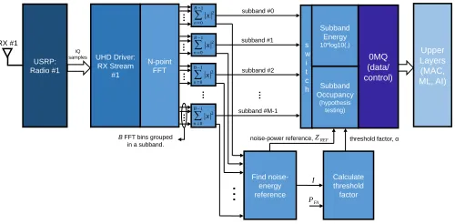
Fig. 4. RF Monitor architecture.
slot, hence allowing runtime configuration. The other two messages, namely, Tx and Rx statistics messages, are used to give real-time feedback from PHY to upper layers, providing vital information necessary for such layers to take actions.
Tx control messages carry the user data (i.e., TB) to be transmitted and Tx parameters related to that transmission such as number of RBs, MCS, data length, Tx gain, Tx channel, Tx PHY BW, transmission timestamp and frame structure type. The transmission timestamp parameter enables time-scheduled transmissions, which allows the implementation of Time Division Duplexing (TDD) or Time Division Multiple Access (TDMA) technologies with the proposed PHY layer.
Rx control messages are used to configure Rx channel, Rx gain and Rx PHY BW. The other two messages, namely, Rx and Tx statistics, are used to inform upper layers of PHY Rx and Tx processing results respectively.Rx statisticsmessages carry the received data and reception statistics related to the received data such as Channel Quality Indicator (CQI), Received Signal Strength Indication (RSSI), MCS, slot error counter, decoding time, etc. Tx statistics messages inform upper layers of transmission statistics like coding time, total number of transmitted slots.
IV. RF MONITOR
As mentioned earlier, this module runs on an exclusive thread and utilizes Radio # 1 of the USRP to act as a spectrum sensing monitor. It monitors and reports on a defined range of spectrum band and can be configured to report either the detected power per subband or subband occupancy (statistical hypothesis testing [24]), i.e., if a subband is free or already being occupied by another transmitter. Figure 4 depicts the architecture of the RF Monitor module.
Subband power reporting is obtained by applying aN-point FFT to the received IQ samples, summing the squared modulus of every consecutiveBFFT bins (whereBmust be a power of two) to formM groups of power samples, i.e., subbands and then, applying the base-10 logarithm in relation to a reference power of 1 Watt to each one of the subbands, resulting in measurements given in dBW. AM-long float array holds the subband power information.
Constant False Alarm Rate (CA-CFAR) strategy [24, 25]. The proposed algorithm is composed of three stages: (i) identification of a set of power samples, I, that can be considered as containing only the presence of noise in order to calculate a noise-power reference value,ZREF; (ii) the number
of power sample values considered for the calculation of the noise-power reference value, and the desired probability of false alarm, PFA, are used in the second stage to calculate
the detection factor,α; (iii) the third stage employs both, the threshold factor and the noise power reference value to test the occupancy of each one of the subbands.
The power samples used in the first stage are also obtained after applying an N-point FFT to the received IQ samples and summing the squared modulus of every B FFT bins into subbands. The procedure used to find the noise-power reference value,ZREF, in the first stage involves ordering the
subbands in ascending order of power. The detection threshold is found by multiplyingZREFby the threshold factor,α. In the
end, there are M subbands which will be tested against the detection threshold, in order to declare whether the subband is occupied or free. If the subband power is greater than the detection threshold, then the subband is declared occupied (true), otherwise it is declared free (false). After testing all subbands, an M-long boolean array holds the occupancy information of the monitored spectrum band. In the current implementation, the probability of false alarm, PFA is set to
10−4. Further information on this algorithm can be found in
[24] and the references therein.
The module allows configuration of the following parame-ters for both types of reporting (power or occupancy): mon-itored bandwidth (through the change of the sampling rate), center frequency, frequency resolution (through the change of the number of FFT bins), number of FFT bins,M, considered as a subband (i.e., number of bins considered for the subband power calculation) and periodicity of the report of statistics. These parameters can be configured in real-time by upper layers through the RF monitor control message. The sensing reporting type, i.e., power or occupancy, is configured during initialization of the framework. The following information is sent to upper layers through an RF Monitor statistics message: timestamp of the moment the IQ samples were received by the USRP and power or occupancy array depending on the configured reporting type.
The RF monitor module is of great importance to spectrum sharing mechanisms as it offers a local insight of the spectrum band usage. It allows upper layers to access spectrum sensing measurements, which can be used to train ML and AI modules to better understand the environment, optimize the spectrum usage/sharing and cooperatively work with other networks without any previous knowledge on the other network’s opera-tion and implementaopera-tion, i.e., without any co-design [26]. For instance, this module allows the implementation of adaptive carrier selection algorithms such as CSAT [27] and can also be used to train ML or AI modules to perform MF-TDMA slot allocation [28].
LBT time-based frame structure
Parameter Value
Clear channel assessment (CCA) time Minimum: 16 [us] Maximum: 190 [us] Channel ocuppancy time (COT) Minimum: 1 [ms]
Maximum: dynamically configurable (tested until 30 [ms])
Clear period Variable. Can be adjusted to comply with 3GPP’s specifications.
Fixed/Variable frame period COT + clear period.
Differently from LAA we can have variable frame periods for different loads and channel usage.
time
CCA CCA
Channel Occupancy Time
Clear Period Variable or Fixed Frame
CCA
Channel Occupancy Time Clear Period Variable or Fixed Frame
Fig. 5. SW-based LBT frame structure.
V. LISTENBEFORETALK
As the other modules in the proposed framework, the software-based Listen Before Talk (SW-based LBT) module also runs on an exclusive thread. The module implements a contention-based mechanism for medium access based on 3GPP’s LAA specifications [29, 30]. However, differently from 3GPP’s LAA specifications, the proposed implementa-tion allows the following configuraimplementa-tions: minimum and maxi-mum contention window (CW) sizes (with the option for the upper limit to be fixed or dynamically adjusted), variable frame period (with configurable maximum COT and clear periods, which allows longer than the standardized maximum frame period [29] and the adaptation to different traffic loads and channel usage) and threshold. Figure 5 shows the proposed variable frame structure supported by the implemented LBT module. The frame period, which is composed of the COT and clear periods, can be dynamically configured to any value greater than 1 ms.
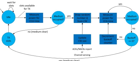
Figure 6 depicts the Finite State Machine (FSM) of the proposed SW-based LBT module, which is explained as follows. Initially, a radio having data to transmit performs a Clear Channel Assessment (CCA) in order to determine if the medium is occupied or clear, i.e., the radio performs energy detection (ED) in given spectrum band during CCA observation time, if the measured energy level exceeds the CCA threshold then the medium is declared as occupied, otherwise, the medium is clear. If the radio finds the medium clear, it may transmit immediately and occupy the medium for the total time of COT.
In case the medium is occupied, the radio must execute a random backoff procedure, where a backoff counter is set to a random number, Q, drawn from a specified interval called the CW [31]. During the random backoff procedure, Q CCA checks are performed for the duration of a CCA observation time, where Q defines the total number of clear periods that need to be observed (i.e., counted) before the radio can transmit. The backoff counter is decremented every time
SW-based LBT FSM
• Based on 3GPP’s LBT specficiations.
• Implementation keeps track of channels’ occupancy statistics (usage). • Statistics can be used to find the optimum channel to be used.
Measure power for CCA time Idle
TX slots
Medium occupied?
Backoff == 0? Decrement
backoff counter
yes
no
yes (medium clear)
no wait for
slots slots available for TX
Measure power for CCA time
Medium occupied?
no (medium clear)
yes
Update CW size
ACKs/NACKs report or Channel sensing
Draw random number Q
from CW
the medium is observed to be clear. The radio may transmit when the counter reaches zero. The random backoff procedure was designed to cope with situations where more than one radio senses the medium as in clear state at the same time, and with this, decreasing the collision probability.
The CW size can be configured to be fixed or dynamic, with adjustable minimum and maximum values. In the fixed mode, Q is always drawn from the same interval, giving different radios the same probability of transmission opportunity in spite of collisions and traffic load. This approach is not fair when coexisting with RATs that adopt exponentially increasing CWs (e.g., Wi-Fi) when a collision happens. In the dynamic mode, a binary exponential backoff mechanism is used in the way that the CW size is increased exponentially based upon the occurrence of a collision (which can be based on feedback reports such as HARQ ACK/NACK or based on channel utilization sensing [32]) and reset to the minimum value when the transmission succeeds. The dynamic mode was devised to improve the overall channel utilization, reduce the collision probability and fairly coexist with other RATs like Wi-Fi.
The following parameters can be configured in real-time by upper layers through an LBT controlmessage: sampling rate, center frequency, CCA threshold, CCA observation time, fixed or dynamic CW, CW minimum and maximum values and idle time. Additionally, the proposed LBT design keeps track of some channels’ occupancy statistics such as chan-nel clear/occupied ratios and clear/occupied average energies. These statistics are reported to upper layers through an LBT statistics message and can be used, for example, to find the optimum channel to be used, i.e., the least occupied channel.
VI. USECASES
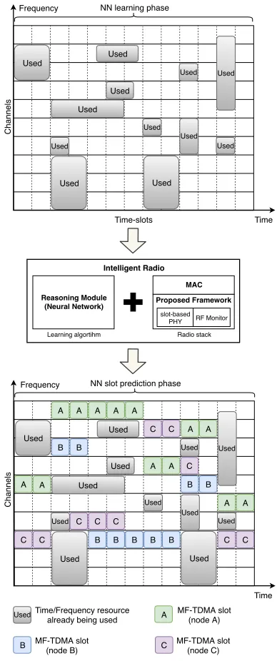
In this section we describe two use cases for the proposed framework. The first one focuses on how the framework may facilitate slot selection in time and frequency domains in order to coexist with other technologies, based on intelligent prediction of the medium usage. The second use case shows how the framework can allow contention-based parameters at MAC level to be optimized when an intelligent upper layer is integrated for specific technologies.
A. Transmission Pattern Prediction
In the unlicensed 5 GHz spectrum band, RATs such as LTE and Wi-Fi use the same spectrum for communications, which often results in cross-technology interference, i.e., interference from spatially close concurrent transmissions that overlap in time and frequency, an event known as collision.
In order to mitigate cross-technology interference, in this use case, the proposed framework is used to implement an intelligent Multi-Frequency Time-Division Multiple Access (MF-TDMA) like network in a congested unlicensed spectrum. Here, the slot-based PHY and the RF Monitor modules are integrated with a MAC layer and a reasoning module featuring a Neural Network (NN) model.
Channels Time-slots Used Used Used Used Used Used Used Used Used Used
Frequency NN learning phase
Used Used Time Time B Used Used Used Used Used Used Used Used Used Used A
B B B B B C C
C C C A A
A A A A C
B
C C A A A A A A
NN slot prediction phase
Used
Used
C C
B B Frequency
Time/Frequency resource already being used
Used A MF-TDMA slot
(node A)
B MF-TDMA slot
(node B) C
MF-TDMA slot (node C) Reasoning Module (Neural Network) MAC slot-based PHY Intelligent Radio Radio stack RF Monitor Proposed Framework Learning algortihm Reasoning Module (Neural Network) MAC slot-based PHY Intelligent Radio Radio stack RF Monitor Proposed Framework Learning algortihm Channels Time-slots Used Used Used Used Used Used Used Used Used Used
Frequency NN learning phase
Used Used Time Time B Used Used Used Used Used Used Used Used Used Used A
B B B B B C C
C C C A A
A A A A C
B
C C A A A A A A
NN slot prediction phase
Used
Used
C C
B B Frequency
Time/Frequency resource already being used
Used A MF-TDMA slot(node A)
B MF-TDMA slot
(node B) C
MF-TDMA slot (node C)
Channels
Channels
Fig. 7. Use case scenario: MF-TDMA free slot prediction.
Use Case: Intelligent RAT Coexistence
collision
Sensing period
CW size increased
COT COT
Idle Time
Idle Time Channel A
Channel B
Channel C
Idle Time
Channel A
Channel B
Channel C
LTE-LAA LTE-LAA
LTE-LAA
Reinforcement Learning Framework PHY LBT
Fig. 8. Use case scenario: Intelligent RAT Coexistence.
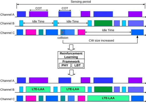
B. Intelligent LTE-LAA and Wi-Fi Coexistence
LTE-LAA enables the deployment of LTE networks in the unlicensed 5 GHz spectrum band. However, when coexisting with LTE-LAA, the performance of Wi-Fi networks primarily relies on how the LTE-LAA parameters are configured, espe-cially parameters such as channel, COT, idle time and CW size that govern the transmission opportunities in LTE-LAA networks.
In order to provide fairer coexistence, LTE-LAA parameters must be dynamically configured based on specific statistics like collision counters, different channel utilizations, i.e., the traffic load present in a channel, etc. In this use case, the proposed framework is used to implement an intelligent LTE-LAA base station (BS). Here, the slot-based PHY and the LBT modules are integrated with a Reinforcement Learning (RL) module, which can feature algorithms like Multi-Armed Bandit or Q-Learning, to maximize the overall capacity per-formance through an efficient coexistence.
The RL module learns how to estimate the activity of Wi-Fi users and consequently adjust the LTE-LAA parameters for several traffic conditions. The main goal is to determine a policy by which the LTE-LAA BS can intelligently choose the optimum channel, COT, idle time and CW size based on collision statistics and measurements taken during the sensing period. Figure 8 shows how the integration of the proposed framework with an RL module can be used achieve efficient RAT coexistence.
VII. CONCLUSIONS
This paper presents a framework that enables experimental research and prototyping for various next generation wireless networks spectrum sharing scenarios. Its high configurability, supported by an interface built upon popular programming libraries (Google protobuf and ZeroMQ), allows engineers and researchers to easily modify it or extend its functions by plugging in new modules implementing novel spectrum sharing techniques and approaches. Additionally, the proposed slot-based PHY is of great importance to combat spectrum
scarcity as it has a pivotal role in providing optimum utiliza-tion of time-frequency resources. These features make it the perfect candidate for an extensive range of spectrum sharing experimentations in real-world or realistic environments such as testbeds aiming at better understanding disruptive spectrum sharing schemes. Two distinctive cases are presented with hints on how the proposed framework could be employed in intelligent spectrum sharing research.
ACKNOWLEDGEMENTS
The project leading to this publication has received funding from the European Union’s Horizon 2020 research and inno-vation programme under grant agreement No. 732174 (ORCA project).
REFERENCES
[1] Federal Communications Commission,Spectrum Policy Task Force Re-port, [available online] https://www.fcc.gov/document/spectrum-policy-task-force, FCC, November 2002.
[2] Gregory Staple, and Kevin Werbach, The End of Spectrum Scarcity, IEEE Spectrum, March 2014.
[3] Andreas Roessler,Impact of spectrum sharing on 4G and 5G standards a review of how coexistence and spectrum sharing is shaping 3GPP standards, IEEE International Symposium on Electromagnetic Compat-ibility & Signal/Power Integrity (EMCSI), October 2017.
[4] Nadine Abbas, Youssef Nasser, and Karim El Ahmad,Recent advances on artificial intelligence and learning techniques in cognitive radio net-works, EURASIP Journal on Wireless Communications and Networking, vol. 2015, no. 1 , pp. 174-194, December 2015.
[5] Seppo Yrjola, and Heikki Kokkinen,Licensed Shared Access evolution enables early access to 5G spectrum and novel use cases, EAI Endorsed Transactions on Wireless Spectrum, December 2017.
[6] J. Mitola,The software radio architecture, IEEE Communications Mag-azine, vol. 33, no. 5, May 1995.
[7] Felipe A. P. de Figueiredo, A Framework for Intelli-gent Spectrum Sensing and Sharing, [online] Available: https://github.com/zz4fap/intelligent-spectrum-sharing, May 2018. [8] Ettus Research LLC, USRP Hardware Driver, [online] Available:
http://files.ettus.com/manual/
[9] Ettus Research LLC, Products, [online] Available:
https://www.ettus.com/product
[10] P. Hintjens,ZeroMQ Messaging for Many Applications, O’Reilly Media, March 2013.
[11] Google,protobuf - Protocol Buffers - Google’s data interchange format, [online], Available: http://code.google.com/p/protobuf/, 2011. [12] DARPA SC2 Website: https://spectrumcollaborationchallenge.com/. [13] DAPRA,Kick-off meeting, The Johns Hopkins University, January 2017. [14] Cristina Cano, and Douglas J. Leith,Unlicensed LTE/WiFi coexistence: Is LBT inherently fairer than CSAT?, IEEE International Conference on Communications (ICC), July 2016.
[15] Houman Zarrinkoub,Overview of the LTE Physical Layer, John Wiley & Sons, January 2014.
[16] Sravanthi Kanchi, Shubhrika Sandilya, Deesha Bhosale, Adwait Pitkar, and Mayur Gondhalekar,Overview of LTE-A technology, IEEE Global High Tech Congress on Electronics (GHTCE), March 2014.
[17] Shao-Yu Lien, Shin-Lin Shieh, Yenming Huang, Borching Su, Yung-Lin Hsu, and Hung-Yu Wei,5G New Radio: Waveform, Frame Structure, Multiple Access, and Initial Access, IEEE Communications Magazine, vol. 55, no. 6, June 2017.
[18] I. Gomez-Miguelez, A. Garcia-Saavedra, P. D. Sutton, P. Serrano, C. Cano and D. J. Leith,srsLTE: An Open-Source Platform for LTE Evo-lution and Experimentation, in Proc. 10th ACM WiNTECH Workshop, October 2016.
[20] ANSI/IEEE 802.11n-2009 ,IEEE Standard for Information technology -Local and metropolitan area networks - Specific requirements - Part 11: Wireless LAN Medium Access Control (MAC)and Physical Layer (PHY) Specifications Amendment 5: Enhancements for Higher Throughput, 2010.
[21] ETSI TR 101.190,Digital Video Broadcasting (DVB); Framing structure, channel coding and modulation for digital terrestrial television -V1.6.1, January 2009.
[22] Gwanmo Ku, and John MacLaren Walsh,Resource Allocation and Link Adaptation in LTE and LTE Advanced: A Tutorial, IEEE Communica-tions Surveys & Tutorials, vol. 17, no. 3, 2015.
[23] 3GPP TS 36.213, Physical Layer Procedures, 3rd Generation Part-nership Project; Technical Specification Group Radio Access Net-work; Evolved Universal Terrestrial Radio Access (E-UTRA). URL: http://www.3gpp.org, May 2016.
[24] Felipe A. P. de Figueiredo, Fabbryccio A. C. M. Cardoso, Jose A. Bianco F., Rafael M. Vilela, Karlo G. Lenzi,Multi-stage Based Cross-Correlation Peak Detection for LTE Random Access Preambles, Revista Telecomunicacoes, vol. 15, 2013.
[25] Janne J. Lehtomaki, Johanna Vartiainen, Markku Juntti and Harri Saar-nisaari,Spectrum sensing with forward methods, in Proc. IEEE Military Commun. Conf., pp. 1-7, Washington, D.C., USA, Oct. 2006. [26] Gen Li, Tan Wang, Qingyu Miao, Ying Wang, and Biao Huang,
Spectrum Sharing for 5G, 5G Mobile Communications, Springer, Cham, October 2016.
[27] X. Wang et al.,Throughput and Fairness Analysis of Wi-Fi and LTE-U in Unlicensed Band, IEEE JSAC, vol. 35, no. 1, pp. 63-78, Jan. 2017. [28] Ruben Mennes, Miguel Camelo, Maxim Claeys and Steven Latre,A Neural-Network-based MF-TDMA MAC Scheduler for Collaborative Wireless Networks, IEEE Wireless Communications and Networking Conference (WCNC), April 2018.
[29] 3GPP TR 36.889, Feasibility Study on Licensed-Assisted Access to Unlicensed Spectrum (Release 13), January 2015.
[30] Mina Labib, Vuk Marojevic, Jeffrey H. Reed, and Amir I. Zaghloul,
Extending LTE into the Unlicensed Spectrum: Technical Analysis of the Proposed Variants, IEEE Communications Standards Magazine, vol. 1, no. 4, Dec. 2017.
[31] Vasilis Maglogiannis, Dries Naudts, Adnan Shahid, and Ingrid Moer-man,An adaptive LTE listen-before-talk scheme towards a fair coexis-tence with Wi-Fi in unlicensed spectrum, Telecommunication Systems, Jan. 2018.