University of Windsor University of Windsor
Scholarship at UWindsor
Scholarship at UWindsor
Electronic Theses and Dissertations Theses, Dissertations, and Major Papers
1-1-1968
Digital computer study of a brushless excited synchronous
Digital computer study of a brushless excited synchronous
machine.
machine.
Dharmendra Kumar Sharma
University of Windsor
Follow this and additional works at: https://scholar.uwindsor.ca/etd
Recommended Citation Recommended Citation
Sharma, Dharmendra Kumar, "Digital computer study of a brushless excited synchronous machine." (1968). Electronic Theses and Dissertations. 6539.
https://scholar.uwindsor.ca/etd/6539
This online database contains the full-text of PhD dissertations and Masters’ theses of University of Windsor students from 1954 forward. These documents are made available for personal study and research purposes only, in accordance with the Canadian Copyright Act and the Creative Commons license—CC BY-NC-ND (Attribution, Non-Commercial, No Derivative Works). Under this license, works must always be attributed to the copyright holder (original author), cannot be used for any commercial purposes, and may not be altered. Any other use would require the permission of the copyright holder. Students may inquire about withdrawing their dissertation and/or thesis from this database. For additional inquiries, please contact the repository administrator via email
SYNCHRONOUS MACHINE
BY
DHARMENDRA KUMAR SHARMA
A Thesis
Submitted to the Faculty of Graduate Studies Through the
Department of Electrical Engineering in Partial Fulfillment
of the Requirements for the Degree of
Master of Applied Science at
University of Windsor
Windsor, Ontario, Canada.
UMI Number: EC52721
INFORMATION TO USERS
The quality of this reproduction is dependent upon the quality of the copy
submitted. Broken or indistinct print, colored or poor quality illustrations and
photographs, print bleed-through, substandard margins, and improper
alignment can adversely affect reproduction.
In the unlikely event that the author did not send a complete manuscript
and there are missing pages, these will be noted. Also, if unauthorized
copyright material had to be removed, a note will indicate the deletion.
®
UMI
UMI Microform EC52721
Copyright 2008 by ProQuest LLC.
All rights reserved. This microform edition is protected against
unauthorized copying under Title 17, United States Code.
ProQuest LLC 789 E. Eisenhower Parkway
PO Box 1346 Ann Arbor, Ml 48106-1346
Approved
j\ Q-cy ■'•s-sr*--*?
Prof. A.Raouf
Dr. P.A.V.Thomas
o / > n ^ d d
i
ABSTRACT
A mathematical model has been developed, for the
simulation of a synchronous machine with brushless excitation.
The model also includes the simulation of Turbine - Governor
connected to the synchronous machine. The model consists of
a set of simultaneous non - linear first order differential
equations in the generalised form suitable for the study of
transient and steady state operation of a synchronous machine.
Using the mathematical model, the behaviour of
a synchronous machine with brushless excitation, during
asynchronous operation and resynchronization has been
studied on a digital computer. Necessary digital programs
for the study have been developed.
ACKNOWLEDGEMENTS
The author is deeply grateful to Dr. 0 . P.Malik,
who supervised this work, for his unfailing and most helpful
advice as well as constant encouragement throughout the
course of the work. .
.
The author also wishes to thank the National
Research Council of Canada for the financial assistance
i i i
TABLE OF CONTENTS
Abstract i
Acknowledgements 11
Table of Contents iii
List of Symbols iv
CHAPTERS
I Introduction 1
II Theory 5
III Digital Computer Simulation 17
IV Digital Simulation Results 22
V Conclusions 3^
Digital Study Figures ' 38
References 62
Appendix I - Runge Kutta Methods for Solution
of Differential Equations 6k
Appendix II - Machine Data 67
Appendix III - Flow Diagram 69
Vita Auctoris 73
LIST OF SYMBOLS
Most commonly used symbols are defined
below. Any symbol not defined below, will be explained where
used in the text. Unless otherwise stated, all quantities are
expressed in per - unit.
Main Symbols ;
p Operator d/dt or no. of phases in the rectifier.
Operator d^/dt^.
e Instantaneous value of voltage,
r Resistance,
L Total self inductance.
1 Leakage inductance.
V Instantaneous Angular Velocity of rotor in
radian per second.
i Instantaneous value of current.
& Load Angle in radians, of synchronous machine,
E Constant or Phasor value of voltage.
F Function.
V se Effective value of a.c. voltage input to rectifier,
t Time in seconds.
V Single Time Constant of the Exciter - Alternator.
T g Synchronous T o r q u e .
V
h . Step Size.
S Step input to a.c. exciter field
K A constant in the Transfer function for the
Exciter - Alternator.
P Power.
T„ Governor Mechanism Time Constant,
O
T^. Turbine Time Constant,
s Slip in Radians per Second.
T P Steady Power that the turbine is set to deliver.
fj_ Instantaneous applied torque.
Synchronous Speed in Radians per Second.
H Machine Inertia Constant in KW sec/KVA.
0 Defined on Page 11.
W Flux linkage.
Subscripts »
Direct Axis
Quadrature Axis
Field winding
Damper winding
Mechanical or Maximum
D i r e c t A x i s m u t u a l
Quadrature Axis mutual
Armature d q f k m m d mq a
INTRODUCTION
1,1 G e n e r a l .
The conventional method of exciting a
synchronous machine is through a D.C.Exciter mounted on the
same shaft as the synchronous machine.
.
1,2In recent years, however, a major step has
been taken by developing brushless excitation system whereby
the need of the ..collector, the collector brushes, the. commutator
and. the commutator brushes has been eliminated. This system
consists- of an a.c. exciter with a rotating rectifier mounted
on the same shaft as the synchronous machine. The output from
the rotating armature of the a.c. exciter is fed along the
hollow shaft to the rectifier whose output is fed to the
P.C. field winding of the synchronous machine.
Selenium Rectifiers were first tried for the 1,2
purpose but their use was not successful . Silicon Diode
R e c t i f i e r s c a p a b l e o f o p e r a t i n g a t r e l a t i v e l y h i g h t e m p e r a t u r e
were then tried and they have been found to be satisfactory.
So far the brushless excitation system has mainly been applied
to aircraft generators and salient pole machines up to about
3 2
1. improved reliability 2. less maintenance and 3* improved
performance.
1.2 Present Work s
The behaviour of a synchronous machine, having
conventional excitation, during asynchronous operation and the
process of resynchronization has previously been studied ,
using a general-purpose analog computer.
In this thesis, the behaviour of the synchronous
machine, with brushless excitation, during asynchronous operation
and the process of resynchfonization has been studied using digita
computer. The digital simulation program developed also takes into
account the speed Governor-Turbine characteristics.
This is believed to be the first time that a digital
program has been developed to study the asynchronous operation
and resynchronization of a synchronous machine with brushless
excitation system.
1.2.1 Assumptions :
To study the behaviour of the synchronous machine
during asynchronous operation and resynchronization, most authors
14-have adopted one or more of the following simplifying assumptions
a) The voltage behind the transient reactance is constant.
b) The variation in speed during the transient process
is small in comparison with the steady-state speed.
c) The effect of all such terms as py>, , py; etc. are
d) The stator resistance of the synchronous machine is
negligible.
The validity of these assumptions, particularly
under asynchronous conditions, is questionable, as the machine
speed can alter considerably from synchronous speed.
In the present thesis, the simulation of the
synchronous machine is by means of the two - reaction theory of 5
Synchronous machines as put forward by Park and presented
6
in a more comprehensive form by Adkins . The digital simulation
of the synchronous machine, as done in the thesis, makes no
further assumptions except those inherent in the two-reaction
theory itself. These assumptions are :
7 a) The machine is ideal, as defined by Park .
b) Symmetrical conditions exist in the system, i.e.,
zero-sequence quantities are equal to zero.
c) Damping circuits can be represented by a single coil
on each axis,
6
1.2.2 Sign Convention s
The voltage impressed on the coil from an
external source is taken as positive.
The positive current is the one measured in the
4
With the above convention, positive power flows
into the circuit from outside, if both voltage and current are
positive.
The convention adopted above corresponds directly
to motor operation and introduces negative quantities for
generator operation.
1.2.3 Per - Unit System i
I
The per-unit system adopted in this thesis is
6
as defined by Adkins .
The advantage of per-unit system is that it
becomes possible to compare machines of different physical
dimensions. Number of turns do not enter the General Machine
Equations. Further, the three mutual inductances on the
direct axis can be assumed to be equal, which makes the
General Machine Equations much easier to deal with.
2.1 Synchronous Machine :
The general machine equations of a synchronous
machine are
'kd
'kq
r f + ^Lmd+
1
f ) P LmdPLmd p r kd+ ( Lmd+
1
k d ) P0 0
iJmdp Lm d p
“•^md^ -•^nd^
0
0
rkq+ m q +J-kq )P
-^mdP
LmdP
0
^mq^ a+ ^ Jmd+ -*-a^ P
LmqP " ^ kmd+^-a^
0 1f
0 ikd
LmqP 1kq
(Lmq+1a )V
ra+ ^ ^Jmq+ -*-a ^ P _ _ i(l _
6
rf 0 0 0 0 if
ekd 0 rkd 0 0 0 ikd
ekq - 0 0 rkq 0 0 ikq
ed 0 0 ^mq^ ra ( L m q + V * id
1
1
0 -(Imd+la )v ra
i iq
(Lmd+1f^ ^md 0 Lmd 0 Pif
i-tad (Lmd+1kd ) o Lmd • 0 Pikd
+ 0 0 0 ^inq
Pikq
i"md i-tad 0 ^ iJmd+ -*-a ^ 0 pld
0 0 ^mq 0 (Lm q +1a)_ _piq _
In. symbolic notation, the above can be written as
i—
i
il
li
'
■ T O r o + 0 ] [pi] ... ( 2. 2 )
•where
DO
'kd
'kq
0
]
DO
M
=
O1
]
=1kd
ikq
id
Tf
0 0 0 0
0 rkd 0 0 0
0 0 rkq 0 0
0 0 iJLriqV
ra
-LmdV -TdndV 0 ” ^ iJmd+ ia)V ra
'md+1f ) Lmd 0 Lmd 0
Lmd ^ iJm d + ikd^ 0 L md 0
0 0 (itaq+i-kq) 0 iqn
Lmd
,T
md 0 0
0 0 i'mq 0 (i'mq
Pif
Pikd
Pikq
Pid
8
Re-arranging the terms, Eqn. 2.2 can be
written as
M [pi] - M
M
[
i
]
or [pi] - W _ 1 [ v ] - [I] ... < *.3 )
-1
The terms of
DO
matrix are denoted by- 1
ajj and the terms of [z] £rJ matrix by bjj , so that
Eqn. 2.3 becomes •
[pi]
-
M
[ 0
-
M
D 1
The actual equation is
pif a ll a l2 a l3 a l U
a l5 ef
Pikd a21 a 22 a 23 a 2^ a 25 ekd
P^kq = a 31 a 32 a 33 a 34 a 35 ekq
P*d a ifl a ^2 a ^3 a 4if a 45 ed
P i q _ a 5l a 52 a 53 a 5it a 55 _ ® q
.
b ll b l2 b 13 b l*f b i5
b 21 b 22 b 23 b 2*f b 25 *kd
b 31 b 32 b 33 b 3^ b 35 ^kq
b 4l b 42 b ^3 H k b 45 id
b 5i b 52 b 53 b 54 b 55 *q
Assuming ekd = ekq = 0 ( Sect. 1.2,1 ),
the following five first order differential equations are ■
obtained :
pif = a 1]Lef + a li4ed + a 1^eq - ( b n if + b 12ikd + b ^ i ^
+ b 1^id + b l5iq )
pikd = a2ief + a 24ed + a 25eq “ ( ^l^-f + t)22ikd + b23ikq
I + b 2ij.id + b 2 5 iq )
pikq = + a 34ed + a 35eq " * b3 1 if + ^ ^ d + b 3 3 1kq .(2.4
+ b ^ i ^ + b ^ i q )
pid = a ^ 1ef + a ^ e d + a ^ e q - ( b/flif + b ^ i ^ a + b^3ikq
+ b4/+id + b45 iq )
piq = a 5lef + a 54ed + a5 5 eq " * ^ l ^ f + b521kd + b 5 3 1kq
+ b 5 4 id + b5 5 iq )
In the thesis, the synchronous machine will be
considered connected directly to an infinite bus. For this
6
case, the following two equations can be written .
ed = E Sin <T
a
m
( 2.5 )
eq =. E m Cos f
Eqns, 2.4 together with Eqns. 2.5 are the basic
equations used to study the asynchronous operation and
10
2.2 Exciter-Alternator and Rectifier i
The rectified voltage of a rectifier may be
8
represented by the Fourier Series
F(0) = Aq + A^Cos p9 + AgCos 2p9 + A^Cos 3P© + ..
+ A mCos mp9 + ... .. + B^Sin p9 + B2Sin 2p9
+ B-^Sin 3p9 + ... + BjjjSin mp9 ... ( 2 . 6 )
Aq represents the mean output steady D.C. voltage
of the rectifier.
O
It can be shown that
A n = 2Vd / ( n 2 - 1 )
&
B ^ = 0where n = mp, m is an integer and p is the
number of phases in the rectifier. The coefficient A n thus
gives the amplitude of the harmonic of frequency n = mp. A n has
a positive or negative sign depending upon the instant of time
in the process of rectification.
The output voltage ripple contains only
harmonics having frequencies which are multiples of both the
supply frequency and the number of rectifier phases,
Q
It can be shown0 that
A0 = v se /” ( p/ n ) Sin ( n /p )
A half wave 3 phase rectifier is taken in the
present studies. For this case, the following can be derived.
Vd = A 0 * 1.17 V se
Since three phase rectification is being
considered, the harmonics present in the D.C. output will be
3rd and its multiples. Therefore,
A 3 = 0.25 Vd
A 6 = 0.0571 vd
A^ = 0.025 Vd and so on.
Harmonics upto the 9th only have been considered
and higher harmonics are neglected since their amplitude is
very small.
In view of the above, Eqn. 2,6 can be written as:
F(6) = Vd + 0.25VdCos36 + O.O571VdCos60 + 0.025VdCos90
i
= Vd ( 1 + 0.25 Cos36 + 0.0571 Cos6© + 0.025 Cos90 )
Assuming that the a.c. supply to the rectifier
is at. a c o n s t a n t f r e q u e n c y o f c y c l e s per second,
0 = w t = 3 l 4 t , Therefore,
F ( 0 ) = Vd ( 1 + 0.25Cos 9^2t +'0.0571Cos 188^1-t + 0.025Cos 2826t )
12
Assuming for the exciter-alternator a single
time constant transfer function of ( K/l+Yp ) ,
K
V - ( s )
se ' « .
1 + V P
+ where S i s the step input to the
exciter-alternator. Therefore,
I .
1.17(K)(S)( l+0.25Cos9^-2t+0.0571Cosl884t+0.025Cos2826t )
P(e) = --- :
---1 + T P
Now, F(0) = e^ , since e^ is the voltage applied
to the field of the main alternator. Therefore,
1.17(K)(S)( l+0.25Cos9^2t+0.0571Cosl88^t+0.025Cos2826t )
e/> = ■' - I--"'—-. '— i .. .... .. ...
i 1 + f p
The above expression, after simplification,
can be written as
1 pef .= _ _ __ ef
1.17(K)(S)(l+0.25Cos942t+0.0571Cosl884t+0.025Cos2826t)
+
'
---Y
.... ( 2.7 )
Eqn. 2.7 is a differential equation of the
first order, the solution of which gives the voltage applied
to the field of the main alternator, from the exciter-alternator
and rectifier combination.
2.3 Turbine - Governor :
9
The Turbine - Governor can be represented by
■ P (s)
P„ = ( 2 . 8 )
( 1 + T p )( 1 + T tp ) 'm
slip s and P .
m
where F(S ) is the steady state relation between
P (s ) can be written as
F (s,) = S + TP . Therefore,
314
S + TP
314
p -
---m
■ ( 1 + Tgp )( 1 + T tp )
The above, after rearrangement, becomes
T T tp2Pffi + ( T + T t )pPm + Pm = ( s/314 ) + TP
Putting pPm = Pm and then simplifying,
pP = _ g w p ‘ _ =-4i- + ™ + TP ... ( 2.9 )
P m T T t m T gT t 3T4
< Tg + T t ) p ,
ra " T 6T
Where pPm = P* ( 2.10 )
Further, the relation between Pm and the
instantaneous applied torque f^ can be derived as^,
I k
or ft ( 2.11 )
The solution of the second order differential
equation represented by Eqns. 2.9 and 2.10 gives Pm< Eqn. 2.11
gives a relation between f^ and Pm .
2.k Synchronous Machine
-Equations for Slip and Load Angle ;
differs from the externally applied torque, if the speed
varies, because of the inertia of the machine, In other words,
Input torque = Output torque + Accelerating t o r q u e .
On the above basis, the following relation
can be derived^..
The torque developed by the synchronous machine
■t
f
t
where V ~ U - p &
Now, - ^md^f + Lmdihd + ( ^md + -*-a ^ ^d
^
^
q “ ^mq^kq ^ ^mq -*-a ^ ^qSubstituting the values of and in the
expression for ft , and simplifying,
Therefore,
?-Eqn. 2.12 Is a second order differential
equation, the solution of which gives slip and load angle.
2.5 Equations for Watts, Vars and Line Current :
The following equations were used for calculating
Watts, Vars of the synchronous machine and the Line Current.
Watts ( ¥ d^q “ ^q ^ d )
Line Current Vars
where and ^ are as defined in Sect. 2,4
2.6 Mathematical Model of
the Brushless Excited Synchronous Machine :
Eqns. 2.4, 2.5, 2.7, 2.9, 2.10 and 2.12 set up
for simultaneous solution on a digital computer form a
mathematical model for the study of asynchronous operation
and resynchronization of a synchronous machine. It may be
pointed out bhat these differential equations are non-linear
since the instantaneous speed V is not constant.
3.1 Choice of the computer technique :
The Computer Program developed has to find
out the solution of the simultaneous non-linear differential
equations mentioned in Sect. 2,6, The solution of differential
equations on a digital computer is a field in which considerable
research is still underway and a single, best method applicable
to all types of differential equation problems has yet to be
discovered. Two of the most commonly used techniques are
the Runge Kutta and the predictor - corrector methods. Both
the categories can further be subdivided depending upon the
type of approximation algorithm used.
The Runge Kutta Methods were used in the present
studies, for the following r e a s o n s ^ !
1) No special starting procedure is required, as the
methods are self-starting.
2) Being self~s:tar.tlng, they permit an easy change in
the step size.
3) A straight-forward computational procedure is
18
k) No modification of the computation is necessary
for non-linear equations or for systems of simultaneous
equations.
3.2 Bunge Kutta Methods used
<■ and Problems Encountered 8
There are various Runge Kutta Methods available
i
I
for the solution of differential equations. The methods
initially considered for programming w e r e ^ ,
1) Basic Runge Kutta Method, 2) Strachey's Process,
3) Boulton's Process and *0 Gill's Process,
The Gill's method was chosen from the above for programming
1 0
due to the following reasons1 s
1) The method is generally more accurate than other
methods d e s c r i b e d .a b o v e .
2) The method results in the economy of computer storage
space. Only three quantities have to be retained at any stage
as against five for Basic Runge Kutta Method and four.for the
other two methods mentioned above.
The Gill's method was successfully programmed
for use in the present studies.
For the present work, it is considered sufficient
if the results are accurate upto the third decimal place.
With this in mind, and also to provide a further check on the
results, it was decided, at a later stage, to try to develop
another program for the solution of the non-linear differential
equations. The Basic Runge Kutta Method was chosen this time.
The program was successfully developed and it was found that
for the accuracy desired, the results agree with those obtained
by the Gill's method. The agreement of the results by two
different methods proves the results to be completely reliable.
In view of the above, it appears that, for the
accuracy of results desired, Basic Runge Kutta Method is
good enough for the present studies. However, Gill's method
still has the edge since, if for some reason, the program
has to be expanded and consequently there is shortage of
computer storage space, Gill's method could provide the answer,
A brief description of the Basic Runge Kutta
Method and Gill's method appears in Appendix I. A flow diagram
of the digital programs is given in Appendix III,
The major problem faced, during programming,
was solution instability. As is only too well known, this can be
a perplexing problem in the numerical solution of differential
equations.
The two major sources of error during numerical
integration are 1) truncation error and 2) rounding error.
Under unfavourable conditions, errors ( which are small
20
for larger and larger values of the independent variable. Thus,
divergence in solution will result.
11
According to McCracken and Dorn , the errors
can be controlled by a proper size of the integration step.
However, it should be realized that a smaller integration step
increases computation time. An optimum value of the integration
step has, therefore, to. be found such that both the error and
the computation time are minimum. In most cases, it is difficult I
to determine the largest acceptable size of the integration
step h theoretically, and a solution is considered reliable
only when it agrees with that obtained at a smaller integration
step1 0 . This is the test of validity of results obtained during
the present studies. Results are compared at intervals h and h/2.
Only if they agree with- each other to the pre-selected degree
of accuracy, are the results accepted. A further proof of the
validity of the results is'that results obtained from two
different Runge Kutta methods give the same results, within the
prescribed degree of accuracy.
The feature of checking the results automatically
with h and h/2 has not been introduced in the c o m p u t e r p r o g r a m .
This was done due to the following reason. The entire program
was run with step h and results obtained. The program was then
rerun with step h/2. The results compared well within the
prescribed accuracy. The results were then compared with the
results from the other Runge Kutta program and these checked
well. Computation time for each study was already running into
many hours. This time would have been doubled if automatic
checking with h/2 had been introduced in the program. This was
not considered necessary in view of the points mentioned above.
All further studies were therefore, performed with step h and
one Runge Kutta program only.
During the digital runs, it was found that
the Basic Runge Kutta method took slightly less time than the
G i l l ’s method. That this can happen, in view of the nature of
10
multiplications in the G i l l ’s Process, is supported by Martin .
All further studies-were, therefore, done by the Basic Runge
Kutta method since the desired accuracy in results was being
CHAPTER IV
DIGITAL SIMULATION RESULTS
k.l General i
During asynchronous operation, e.m.f, will be
induced in the synchronous machine field circuit. Depending
upon the design of the machine and magnitude of slip during
i
asynchronous operation, these vpltages could be quite high,
and the rectifier may be damaged, Short circuiting devices
are available which provide complete protection for the rectifi
12
under these overvoltage transients . This study assumes that
the rectifier is short circuited during asynchronous operation.
The power and electrical torque developed in a
synchronous machine, during asynchronous operation, depend
not only on the load angle, but also on the time rate of change
i
of load angle. Torque ’T ’ can then, as an approximation, be
considered to be made up of a synchronous component and an
asynchronous component.
T = T s .+ Tas
The synchronous component will be present only
when field excitation is present during asynchronous
operation.
4.2 Studies performed :
To study the effect of various parameters on
machine behaviour ( the machine data is given in Appendix II ) ,
during.asynchronous operation and resynchronization, the
following studies were performed s
Study 1 ) Field Resistance = 0,00446 p.u. No excitation during t
i •
asynchronous operation, i.e., a.c. exciter field shorted on
itself. Turbine output = 0.75 p.u.
Study 2 ) Field Resistance = 0,00089 p.u. No excitation
during asynchronous operation. Turbine output = 0.75 p.u.
Study 8 ) Field Rdsiisbance = 0.00446 p.u. No excitation during
asynchronous operation. Turbine-Governor output = 0.75 p.u.
A.C, Exciter-Rectifier combination is not included in this
study, i.e., the machine has conventional excitation ( Sect. 1.1 ),
Study 4 ) Field Resistance = 0,00446 p.u. No excitation during
asynchronous operation. Turbine-Governor output = 1 . 0 p.u.
Study 5 ) Field Resistance = 0.00089 p.u. No excitation
during asynchronous operation, Turbine-Governor output = 1 , 0 p.u.
Study 6 ) Field Resistance = 0,00446 p.u. Field excited during
asynchronous operation. Turbine-Governor output = 1.0.p.u.
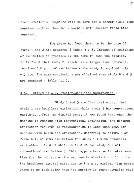
4.3 Pulsation in various quantities
during asynchronous operation :
performed above are given in Pigs. 4.1 to 4.24. It will be
observed from these figures that, during operation with the
a.c. exciter field excited, the quantities fluctuate much more
violently than with field short circuited and unexcited.
4.3»1 Slip Pulsations :
Pigs. 4.1, 4.5. 4.9, 4.13, 4.17 and 4.21 give
the variation of slip with respect to load angle, for the various
studies performed. Figs. 4.2, 4.6, 4.10, 4.l4, 4.18 and 4.22
give slip variation with respect to time.
Prom the figures mentioned above, it can be seen
that in most of the cases studied, the machine went through
brief intervals of synchronous motion during each slip cycle.
At these intervals, the machine tended to lock, but after a
brief interval of synchronous motion, went again into the
next slip cycle.
Prom the graphs, it is found that the magnitude
of slip pulsation is inversely proportional to the mean slip.
Thus, at a mean slip of - 0.765 %, the variation is between
-1.57 % a n d 0 . 0 4 8 %, Pig. 4.1, a n d a t a m e a n slip of -0.605 %,
the variation is between -1.9 % and O.706 % % Fig. 4.5.
The effect of reduction in field resistance,
for the same p.u. power, is to increase the magnitude of slip
pulsations and decrease mean slip.
This can be verified from Pigs, 4.1 and 4.5 and also from
Pigs. 4.13 and 4.17. In the first instance, as the field
resistance was changed from 0.00446 p.u, to 0.00089 p.u., the
magnitude of slip pulsations changed from -1.57 % to -1.9 %
and from 0,048 % to 0,706 %. The mean slip dropped from - O.765 %
to - O.605 %< In the second instance, with the same change in
the field resistance, the magnitude of slip pulsations changed
from -2.04 % to -2.6 % and from -0.045 % to 0.65 %• The mean
^lip dropped from -1,05 % to -0.975 %• The increase in slip
pulsations is due to the fact that with reduction in field
resistance, the asynchronous torque component produced by the
shorted field circuit is increased with a resultant decrease in
mean slip. Due to the asymmetry of the rotor field circuit,
this torque is not constant but pulsating. Thus, the higher
proportion of pulsating torque increases the magnitude of
slip pulsations.
A comparison of Figs. 4.1 and 4.9 shows that,
with Exciter-Rectifier combination in or out, the slip
pulsations are practically the same. Thus, slip pulsations
are practically unchanged, whether there is conventional or
brushless excitation.
It is also seen from the studies performed that
mean slip is higher when turbine power is increased to meet
the increased load demand of the machine. This has to be so
2 6
as increased load demand can be supplied only by an increase
in mean sli p . .
4.3.2 Pulsation in Current :
Figs. 4.3, 4.7, 4.11, 4,15. 4.19 and 4.23 show
the fluctuations in field current and line current under
various modes of operation.
With reduction in field resistance, the amplitude
i
of field current increases. This can be seen by comparison of
Fig., 4.3 with Fig. 4.7 and of Fig. 4.15 with Fig. 4.19. With
field excited, the amplitude is further increased and pulsations
are at slip frequency. With field unexcited, they are at twice
the slip frequency.
Due to the large reactive-power demand of the
machine, the line current during asynchronous operation is high.
The pulsations are more violent in the field excited case than I
the unexcited one. The magnitude of line current is also
directly dependent on the power output.
4.3.3 Pulsations in Watts and Vars ■.
Figs. 4.4, 4.8, 4,12, 4.16, 4.20 and 4.24 show
the fluctuations in watts and var.s during various conditions of
asynchronous operation.
Pulsations in both the quantities follow the
same pattern as that of slip. The magnitude of variation
depends directly on the output of machine and slip. The field
excited case produces more violent fluctuations than the
unexcited one.
Comparison of asynchronous operation
with different field excitations ;
■-3T
In the present work, only two modes of field
connections are considered s
i. Field excited
ii. Field unexcited and shorted.
In the case of field excited synchronous machine,
the following points are observed when compared to the field
unexcited case :
a) The pulsations in various quantities are at slip
frequency and are more violent than the unexcited case. Thus,
there are greater chances of the entire system getting disturbed.
b) For the same turbine power, the slip pulsations are
higher. This is because magnitude of pulsation depends directly
on the value of the synchronous component of the torque.
2 8
4.5 E f f e c t of R e c tifier-Exciter c o mbination
on Asynchronous operation :
A comparison of study 1 and 3. Sect. 4.2, shows
that pulsations in various quantities during asynchronous
operation is the same whether brushless excitation or
conventional excitation is there.
4.6 Resynchronization :
With the synchronous machine operating in a
steady asynchronous state, different values of excitation
voltages were applied to the a.c. exciter field to find the
minimum excitation required for resynchronization for a certain
run. After obtaining the minimum magnitude of excitation
required, the instant of voltage application was delayed
so as to obtain the maximum value of the load angle at which
the excitation must be applied or boosted to achieve
synchronism.
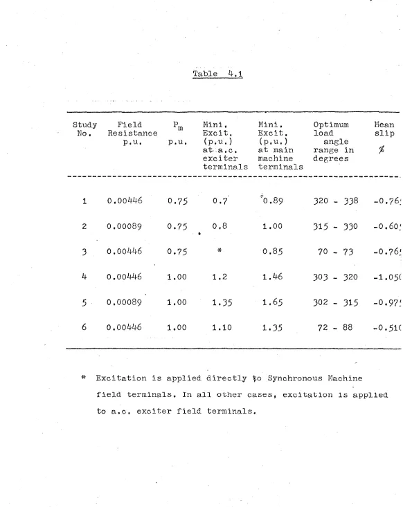
T a b l e 4.1 g i v e s the v a l u e s of minimum excitation
for resynchronization and farthest load angle at which time the
machine would still resynchronize, for the various studies
performed. Column 4 of Table 4.1 gives the excitation voltage
applied to the a.c. exciter field terminals. Column 5 gives the
corresponding voltage that appears at the main machine field
Table ^-.1 Study No. Field Resistance p.u. Pm p.u.
M i n i , E x c i t .
(p.u.) at a . c . exciter terminals
M i n i , E x c i t .
(p.u.) at main machine terminals
Optimum load
angle range in degrees
Mean slip
%
1 0.00446 0.75 0.7 "0.89 320 - 338 -O.7 6:
2 0 . 0 0 0 8 9 0.75 0 . 8
• 1 . 0 0 315 - 330 -0.6 0'
3 o.oo446 0.75 0.85 70 - 73 -0.76'
4 0 . 0 0446 1 . 0 0 1 . 2 1.46 303 - 320 -1.05C
5 0.00089 1 . 0 0 1.35 1.65 302 - 315 -0.97'
6 o.oo446 1 . 0 0 1 . 1 0 1.35 72 - 88 -0.51C
* Excitation is applied directly Synchronous Machine
field terminals. In all other cases, excitation is applied
3P
terminals. It takes some time for the voltage at machine
terminals to build up to this final figure, due to the time
constant of the a.c. exciter ( Sect, 2-,2,),.The table also
gives the value of mean slip for each study. As mentioned
earlier, study 3 ( Sect, b.2 ) has conventional excitation
4'
( Sect. 1.1 ) while all other studies have brushless excitation..
FjUrther, study 6 has field, excited and the magnitude of
! '
excitation of the a.c. exciter during asynchronous operation
is 0,9 p.u. All other studies have a.c. exciter field unexcited.
It was possible to obtain only a range for the value of farthest
load angle. This was because the digital computer prints output
only at preselected machine time intervals. Thus, i*e synchronization
can be performed, during digital study, only at the load angle
values printed out,
k.6,1 Effect of Field Resistance ;
When the machine field resistance r^ is varied,
the field, time constant is changed. Due to the field time
constant, the field current does not attain its full value
i m m e d i a t e l y at the i n s t a n t o f s w i t c h i n g . F o r a m a c h i n e w i t h
larger field time constant, it will take more time to reach the
full magnitude of field current. A larger time constant field
would thus require the excitation to be switched in much earlier
than the field w i t h a smaller time constant. This can also be
put in an alternative form, that, for the same instant of switching
field, excitation required will be more for a larger field time
constant machine than for a machine with smaller field time
constant.
The above has been shown to be the case if
study 1 and 2 are compared ( Table ^.1 ). Instant of switching
of excitation is practically the same in both the studies.
It is found that study 2, which has a larger time constant,
requires 0.8 p.u. of excitation while study 1 required only
0.7 p.u. The same conclusions are obtained when study k and 5
are compared ( Table k-.l ).
k,6.2 Effect of A.C. Bxciter-Rectifler Combination t
Study 1 and 3 are identical except that
study 1 has brushless excitation while study 3 has conventional
excitation. From the digital runs, it was found that when the
machine is running with conventional excitation, the minimum
excitation required to resynchronize is less than that for
machine with brushless excitation. Referring to column 5 of
Table ^.1, minimum excitation for study 1 ( with brushless
e x c i t a t i o n ) is O.89 w h i l e it is O.85 f o r study 3 ( with
conventional excitation ). This happens because it takes some
time for the voltage at the machine terminals to build up in
the brushless excited case, due to the a.c. exciter time constant.
3 2
For the same reason, the farthest load angle is more in
study 3. The difference is quite significant in this case,
4.6.3 Mode of Field Connection ;
In this thesis, two modes of field connection
during asynchronous operation have been studied, i. Field
shorted and unexcited ii. Field excited. Effects of these
modes of operation on resynchronization are now discussed.
■t
For this purpose, studies 4 and 6 are
compared. For study 6, which has field excited during
asynchronous operation, it is found that the minimum value of
excitation required for resynchronization is less than that
for the field unexcited case. This happens because the time
required for the field to be fully effective is less in the
excited case. Therefore, a lesser excitation suffices to bring
the machine in synchronism. It should be noted that, in study 6,
the field excitation during asynchronous operation is quite
high. In fact, it is more than 80 % of the value required for
resynchronization. Also, due to the reasons mentioned above,
the o p t i m u m a n g l e o f r e s y n c h r o n i z a t i o n is s i g n i f i c a n t l y m o r e
in the field excited case.
A. 6. A Effect of Power Output :
As the power output is increased, the
magnitude of mean slip to produce the required induction
torque is also increased. Thus, there is an increase in the
additional stored kinetic energy in the rotor. The additional
energy must be pumped out to establish synchronous conditions.
This means that more excitation would be needed to bring the
machine back into synchronism as- the power output is increased.
This is indeed the case as can be seen from the figures for
CHAPTER V
CONCLUSIONS
5.1 A review of results i
Asynchronous operation and resynchronization
of synchronous machines has been studied by many investigators
Most of these authors have adopted one or more simplifying
assumptions ( S e c t . 1.2,1 ). These assumptions are not valid
for modes of operation of the synchronous machine being studied.
In the present work, no additional assumptions are made, except
5 6
those inherent in the two - reaction theory itself-" .
A mathematical model has been developed to
study the behaviour during asynchronous operation and
resynchronization, of a synchronous machine with brushless
excitation system. Representation of a turbine - governor
is also included in the mathematical model.
The mathematical model has been simulated
on a digital computer. Runge Kutta Methods have been used for
the simulation. It has been shown that, for an accuracy upto
third decimal place, Basic Runge Kutta Method is good enough
for the present studies.
Using the digital program developed,
a number of studies were made to study the effect of various
parameters on machine behaviour during asynchronous operation
and resynchronization. A summary of the more important
conclusions arrived at, is given below.
5 . 1 »1 Asynchronous operation ;
1, Asynchronous operation with field unexcited produces
less disturbance in the system than the field excited case.
2, Pulsation in various quantities is practically the
same whether the machine has conventional excitation or
brushless excitation,
5.1.2 Resynchronization ;
1. When the field is excited during asynchronous state,
lesser excitation is needed to resynchronize the machine than
i
that required when the field is unexcited.
2. When the machine is running with conventional ..
excitation, the minimum excitation required to resynchronize
is less than that for a machine with brushless excitation.
Also, the optimum load angle at which the machine would still
synchronize is more when the machine is conventionally
36
5.2 Further Work t
5.2.1 Effect of Rectifier on
asynchronous operation. :
To protect the rectifier against overvoltage
transients, short circuiting devices are available which
short circuit the rectifier under asynchronous condition
( Sect, k.l ). In the present studies, it has been assumed that
the rectifier is protected by the above device.
Such protection, against asynchronous
operation, is not always required, as, for example, if the
12 asynchronous operation is for not more than a few cycles
If the rectifier is thus allowed to remain in circuit during
asynchronous operation, asymmetry is introduced in the field
circuit, due to the difference in forward and backward resistance
pf the rectifier. This may considerably affect the operational
characterestics of the machine and would be worth further
investigation.
5.2.2 Step length in Digital Program :
The digital computer studies were done on
IBM 1620 computer. As this is only a medium sized computer,
the time required for each run was in terms of many hours.
For this reason, the feature of automatically checking the
results with half the previous step size was not incorporated
in the program. In the present studies, this could he done
for the reasons already mentioned in Section J.2. However,
it+is suggested that this feature be incorporated in the
digital program for further studies, if a faster digital
11X
trttt ifi:
[+Bx
^ o
in:
-.tt±
•J35 V3d 'SQVV. N! d IIS
40
^ r r r —n rrrrrrrrrrr;
-H- -! • i H-{ M H'-f H f-:
.TV.
Til
trt
T.t 4’
i-Thr
44
-11'
trr
TC
Vn;d)±N9V}tfi? 9A//7
(77V)XA/2*/*rt:> <77=?/;*
H
.
CkV5 ^
ij±i
ffilUt
k2
H+it
rPrtBr>: vi Q£
lj:.n:
.tit
&ri
:ttr
TTT
}3s *3d '.sav'd; Ni <jns
h-H:
4i
-i-i-at
■*r-r
Tt-t
Tt+l
hv±-irfcr
tif tit]
xix
+U‘
nd)xNdyvno cni/x
(id) XNayyao i n h.irr
Csl O N N o
335 v a d ' s a v b Ni d I I S
(•n-d) j . N 3 w n o s u n
( O d ) X N V W n O 0131 j
tr' ”
P ' t l u i C fT-fti
Si-fU- n
i h i t i n
m m
. :j\hj.\
Kjtjin
m u N
(IIIhH -I
rmjrtiih
hrH-H
lyx-ri ,.f!...;ii.!:.
Vnd) JLN3ddno ~ 3n h
( n d ) x N a a v n o a~>3t j
4.li|
m
ij±S±£±:ili
th i £LU:f|r ! ' -:T!7jtp M-!|
■ f t # i::±.
■trfiu
RRTR'fj
r;j ;
-M-+ -M-+: trf
111:
I+f
:iif.
_J±
tffi
t±i-j
tttt-ittf
i:: H
J-f
P 3 5 i / 3d - s a w , A// . dl ? $ ■ ITTTTT
c\
TH-il l:
Tn
n . t
n . l :
T] n;
rx;50
s < i y y a / / «y / *7 s
S
N cM CM O
^('Od) JLA/3\ddno 0 73IJ ('fid) X.N3ddnO 3 N H
i ; ' " : : ' . ' ' • ' 1 \ ’ ' * ■ 1 •I... ■ ■ ■ ‘ - • __ ^ : _
J. . • . ' • 1
f;'?
' r i T^r r uTnf T- r :F
O
-
:
1
:T;Tr:T : f
H — '- H - - t ' f ---11 ; : t"1 '■■■■■• f i-: - -■ ! • • r - ‘ !•;--.••< - i — •■-•> H i ■] •• — - ^ - r - , ...;. ,-.-r . i }--- . --- ; , .. .. . ; , • . . - •
| | i f r ^ p F i ] T | 7 i n i j j ^ n T R j f r i T i r i | r ^ l :^TTTriTrF^'-rr ^:*T^^:^^
i'
R e p ro d u c e d w ith p e rm is s io n o f th e co p yrig h t o w n e r. F u rth e r re p ro d u ctio n p ro h ib ite d w ith o u t p e rm is s io n .
T
/
M
E
'
//
V
S
e
c
s
f*
:t! ’ ■'•i/i ‘
‘-±H -fcV,-.7
: -rr:l:i.U4: ;.!:
Si
(•n-j) s'nva
Vn-d) sj-jLVfA
■til
ll-i
trr
v» OC
oa
5;;v
3d 'sav'd Nt dns
©
(•n d) X N 3 V V 0 0 Q 1 3 U ( • n d ) x u a n d no 3n i i
62
REFERENCES
/ 1. Ferguson R.W., Herbst R . , -Miller R . W . : 'Analytical Studies
of the Brushless Excitation System', T r a n s . Amer. Inst.
Elec. Engrs., i960! 7 8, Pt.IIIB, PP 1815-1821.
v 2. Whitney E.C., Hoover D.B. , Bobo P.O.: 'An Electric Utility
Brushless Excitation System', ibid., PP 1821-1828.
I
3. Twardzicki A., Coleman R.W.T.: 'Brushless Salient - Pole
A.C. Generators. I', Electrical Times ( GB ), Vol. 152,
No. 8, PP 269-272 ( Aug. 24, 1967 ).
4. Malik O.P., Cory B . J . : 'Study of asynchronous operation and
resynchronization of synchronous machines by mathematical
models', Proc. IEE, Vol. 113, No. 12, Dec. 1966, PP 1977-1990.
5* Park R . H . : 'Two - reaction theory of synchronous machines,
1 Pt.I', Trans. Amer. Inst. Elec. Engrs., 1929, Vol. 48, P 716.
6. Adkins B . : 'The general theory of electrical machines'
( Chapman and Hall, 1964 ).
7. Park R.H.: 'Definition of an ideal synchronous m a c h i n e ',
Gen. Elec. Rev., 1928, Vol. 31, P 531.
•8. Rissik H . : 'Mercury Arc Current Convertors', ( Sir Isaac
Pitman & Sons, Ltd., 1935 ) PP 278 - 2 8 9.
9. Sudan R.N.: 'Digital Computer Study of the resynchronizing
of a Turboalternator', Trans. Amer. Inst. Elec. Engrs,,
1961, Vol. 79, Pt.III, PP 1120 - 1129.
10. Martin D.W.j 'Runge Kutta Methods for Integrating Differential
1 Equations on High Speed Digital Co m p u t e r s ’, Computer Journal.,
1958, Vol. 1, PP 118 - 123.
1
! '
11. McCracken D.D., Dorn VI.S.; 'Numerical Methods and Fortran
Programming', John Wiley and Sons, Inc., 1965, PP 328 - 329*
12. Rosenberry G.M.s 'Brushless D.C. Excited Rotating Field
Synchronous Motor', Trans. Amer. Inst. Elec, Engrs., i9 6 0,
64-a p p e n d i x I
RUNGE KUTTA METHODS
Nomenclature
tQ = initial value of t.
h = step size
tn = nh + tQ
m = the total number of first order simultaneous
equations that must be solved,
( .1 = 1, ... , m ) = the value of any one of the
If the values of the dependent variables in the
m first order differential equations are given at t = tn ,
the following algorithm is used to find their numerical values
at tn+1 = tn + h »
dependent variables at t = tn .
• • • •
1 0
Basic Runge Kutta Method s
(i) (i)
(i)
(i) (i) (i) (i) (i)
where A Yn
(i) (i) (1) (2) (m)
and kQ = f (■ t ^ , Y^ t Y^ , . . . > f Yj^ )
(i) (i) (1) k ' 15 (m)
k^ = f (tn+(h/2), Yn + ^ h, ... f Y n + g
(1) , .
(i) (i) (1) k x _ v (“ ) k l . ,
k 2 = f (tn+(h/2), Yn + ~ L — h, Y n + — — h)
2 ^
(i) (i) (1) (1) (m) (m)
k^ = f (tn+ h # Y n + k 2 h, ... f Y n + k 2 h)
and the superscript i = 1,2,3» m serves
to indicate the m first order differential equations.
Gill Method10
I f th e v a lu e s o f th e dependent v a r ia b le s in the
m f i r s t o rd e r d i f f e r e n t i a l e q u a tio n s a re g iv e n a t t = t n , .
th e fo llo w in g a lg o r ith m is used to f in d t h e i r n u m e ric a l
v a lu e s a t t n+^ = t n + h :
( i ) ' ( i ) ( i )
^n+1 = ^n + A Y n
( i ) h r ^ r- ^ r- ^ ( i ) l
where A Yn = —— k0 + 2 ( 1 - 1 / y 2 )k ^ + 2 ( 1 + 1 / v/
2
)k 2 + k^ I( i ) ( i ) (1 ) Cm) and k = f ( t n , Yn , , Y n )
(i) (i)r ( O k * 15 (m) k^m) r
(tn+ (h / 2 ) , Y n + — — h, Y n +
66
(i) (i)
k 2 = f
(1) 1 y (1) 1 (1)
tn+(h/2), Y n +(- | + y | ^ o h, ...
(m) 1 n (m) 1 (m)
, Xn + <- - +/|)k0 h + d - l j k i h
d ) (i)
kj = f
(1 )
-
(1 )
(1 )
tn+h, Yn +(- £)ki h + (1+ -)k2 h, ... 7 ?
(m) . (m)
(m)
,,,., Yn +(~ -)kj h + (1+ ^2 h
v/2 7 2
and the superscript i = 1,2,3,... m serves
to indicate the m first order differential equations.
t. Synchronous Machine
L a m i n a t e d rotor micro - m a c h i n e :
Stator No.
Rotor No.
334819
334818
Base Quantities :
V o 1 tamps 1525 VA
Voltage (phase) 12? Volts
C u r r e n t (phase) 4 Amps
Impedance 31.75 Ohms
Field C u r rent 0.519 A m p s
Synchronous Speed 314 Radians/sec
Parameters in p.u. s
a
a
kd
Lkq
0.007
0.00446
3.64 KW sec/KVA
0
.
0006?7
0.00031
0.000122