Emergency Handling System
Maznah Kamat Anazida Zainal Rashidah Kadir
RESEARCH VOTE NO. 71845
Jabatan Sistem & Komunikasi Komputer Fakulti Sains Komputer & Sistem Maklumat
ABSTRACT
Emergency Handling System
(Keyword : Mobile positioning technology, security, wireless technology)
The current emergency handling services are cumbersome; a caller needs to dial 999 in order to report an emergency. In most occasions civilians are urged to call an emergency centers, which normally not
remembered by many. The distance between the occurrence of the incident and the center remains as the major aspect for instant assistance. An
assistance may not able to reach at soonest time if caller fail to describe his/her exact location. Worst of all the current system hinders handicapped from reporting an emergency. The advancement in wireless technology and infrastructure has amplified the usage of cell phone in our lives, therefore a location-based ah hoc emergency handling system is a value-add to the 999 service.
This research studies the issues in providing an emergency handling system (EHS), which deploys location based technology that will detect the location of a caller and connect to database server that store required data. The system enable user to forward distress message either to police station, rescue team, hospital and etc. The professional application checks an emergency message, view location of an incident and respond to an
emergency request. The system employs CGI+TA technique in determining the locations of caller and the nearest professional within the incident
CHAPTER 1
INTRODUCTION
1.1 Overview
Mobile Positioning System (MPS) and General Packet Radio Services (GPRS) are the two technologies, which are related to Pervasive Computing. Research done by American Telecommunications Consultancy Strategy found almost a quarter (24%) of potential location customers is interested in the emergency services being able to automatically disclose their physical location. Over the last few years, there has been significant technology development for mobile location services support in wireless network.
However, most location-based services are based on GSM network standard. Since GPRS technology has been unfolded, deploying mobile positioning on GPRS bearer, as
proposed in this EHS provides more benefits than before. EHS is developed as a mobile application that enables a registered user to initiate distress request to nearby doctor, simply by pressing three clicks on his mobile phone. He can also attach voice message to describe his distress situation. User’s distress request is sent together with his location information to the nearest doctor and police (if necessary) in a real-time manner. The nearest hospital will be notified by the system as well.
This project is proposed due to the increasing number of death tolls due to late rescue. Today’s scenario in reporting the accident is still considered inefficient. However, most location based services are based on GSM network standard. Since GPRS
technology has been unfolded and keeps progressing, deploying mobile positioning on GPRS bearer, as proposed by EHS, provides much more benefits than before. In fact, with Mobile Positioning System (MPS) and GPRS technology the nearest rescuers can be notified sooner and the death toll can be reduced dramatically.
1.2 Background and Problem analysis
Sometimes we just cannot prevent emergencies, accident, fire, robbery and health problem to be happened around us. When facing these problems, we will try our best to pacify the condition by seeking proper assistance in the soonest time. However, there always exist some constraints that worsen the situation; lack of public facilities such as phone booth or the incident occurs at remote area.
Many callers who report an emergency fail to describe their exact location mainly because unfamiliarity or being too anxious. The situation becomes worse when the victim is unconscious. These problems may delay rescue and cause unnecessary sacrifices.
The distance between the victim and the rescuers remains as the major aspect for instant assistance. Normally, victim will make emergency calls directly to police station or hospital and have to wait for assistance. The stations may be situated far way and the rescuers will not reach them immediately. However, it is much more efficient if we can gain services from the nearest rescuers who are on duty perhaps a few meters away from the victim.
problems. However, how many people will remember the number of nearby emergency centers?
Panic and anxiety of victim when emergency occurred sometimes can not be prevented. People may lose his or her conscious and stunned when facing emergency thus fails to take proper first aid treatment. For some cases like drowning or bleeding, immediate first aid treatment is a must to pacify the condition of the victim. Otherwise, the further aid will become in vain if professionals fail to arrive on time. In addition, victim always worries about whether the rescuers are coming immediately after the emergency request is made. Victim’s frantic emotion will certainly increase his or her pain.
Any information that is transferred over wireless link is susceptible to
interception. Abusing the usage of emergency number is a common problem faced by many call centers. To ensure that the emergency request is genuine, a user of mobile terminal is required to be authenticated and validated. An important issue the system should handle is the action that can be taken if a mobile phone is lost or stolen. If nothing is done, anyone who is holding the phone will be able to make a phony emergency
request and the owner has to be accountable to the call.
Handicapped user, particularly dumb and deaf always has difficulties when making emergency request via telephony system. Accessibility must be enhanced in telephony system, especially mobile phone that provides text-based data transferring such as SMS, to allow disabled people make emergency request.
1.3 Project’s Vision
This project aims to develope a value-add emergency handling system that able to handle an emergency calls automatically without an operator assistance.
1.4 Project’s Objectives
In this project, a design and prototype of an emergency handling system which handle emergency request from cellur users was developed. The software also enable handicapped user to send a distress message for an assistance without having to call a center. In addition the location of the caller is automatically detected which enable an assistance to reach the site at soonest time.
To achieve the goal of the project, the following objectives were outlined:
i. To apply Mobile Positioning System (MPS) on GPRS transmission.
ii. To develop EHS capable of initiating request and response via mobile phone and revealing caller’s location.
iii. To produce user-friendly yet secured mobile application.
1.5 Project’s Scopes
i. Mobile positioning system will be developed using an emulator.
ii. Application delivered to mobile phones as a downloadable and upgradeable application.
iii. Forward the distress calls to nearest doctors and the nearest hospitals.
CHAPTER 2
LITERATURE SURVEY
2.1 INTRODUCTION
In this chapter we present a survey on the evolution of emergency handling system, position location technique, comparison of several implementations of wireless E-911 and wireless security. The study provides us an excellent background and challenges in designing the value added emergency handling system.
2.2 Evolution of emergency handling process
An emergency due to injury, illness, fire or crime occurs without being anticipated and it can strike anyone, anytime, anywhere [Osha]. When facing such emergency, one will try to seek proper assistance in the soonest time while first aid should be available within 3-4 minutes. To enable emergency personnel to reach an emergency site, an effective
emergency communication is vital [Osha].
implemented quickly. In 1968, AT&T announced that it would establish the digits 9-1-1 as the emergency code throughout the United States [Northwest Allegheny].
A caller has to go through the following procedures when requesting for an assistant [Emergency911callhandling]:
i. State clearly the kind of assistance needed: Police, Fire or Medical
ii. Stay on the phone and answer all questions and follow directions instructed by the dispatcher. Typical questions that will be asked are as follow:
a. Name, address and phone number b. What is happening
c. If it is a crime, the caller will be required to describe the suspect and the direction the suspect is heading
iii. Give specific location
iv. Caller is require to stay on line until emergency personnel arrives to the scene.
In Malaysia, 999 is designated as the emergency telephone number. In case of fire and rescue operation, one may dial 994. The procedure of handling emergency call is equivalent to what is being practice in USA. After dialing the emergency number, the caller will be connected to the operator on duty. Based of the information gathered, the operator will determine which assitance should be send (police, fire brigade etc).
The concept of a universal emergency telephone number has been around for many years. England was the first country to establish a universal emergency telephone number. Ever since 1937, 9-9-9 has been used to put an individual in contact with
emergency service personnel [Northwest Allegheny]. [emerge_no_worldwide] lists most of emergency numbers around the world. The three-digit number was chosen because it meets public requirement; it is brief, easily remembered, and can be dialed quickly [Northwest Allegheny]. In addition, it is a unique number, never having been authorized
All the above mentioned fixed-line emergency telephone number provides only a voice connection to a predetermined emergency center. Having the basic emergency number was a major step towards decreasing emergency service response time, on the other hand the technology did not yet have the ability to tell the emergency responders who was the caller or from where the call was originating. The general procedure for handling emergency request enables the emergency responders to gain basic information such as callers’ names, fixed static addresses and phone numbers. But with the enhance 911 (E-911), the emergency dispatchers that takes a call will automatically receive the basic information displayed on the computer screen. This enhanced 911 system maximizes the dispatching efficiency of emergency assistance to the public in times of crisis even if the caller is unable to communicate.
The significant of wireless devices in today’s world has intensely amplified, yet the rapid proliferation of wireless phones has reduced the efficacy of the E-911 system. This is due to lacking in the current mobile communication networks, inability to provide emergency dispatchers with automated caller location or identification information. This has lead to dramatic and detrimental outcomes for some users who were unable to describe where they were or were physically unable to communicate. If systematic improvements aren't made soon, the life-saving capabilities of our emergency
communications system will be severely limited. The proliferation of wireless phones
2.3 Location-based System
The emerging positioning technologies have enabled the design of an application called Location-Based Services with the capability to pinpoint the geographical location of a mobile subscriber and provide the user with relational information according to the location determined. The mobile positioning market is driven by both legal and commercial concerns. Many governments already require or will soon require that emergency service operators have positioning systems in place to allow tracing of emergency calls. The technology also creates numerous new business opportunities that companies want to capitalize on.
Based on features, requirements and functionality, most popular location based services can be classified into three classes; Location Information, Traffic and Tracking Information and also General [Nicky et al 2002]. For example the mobile E911, Police and Ambulance as well as Rescue Service belong to General class. Provisioning location-based services for either business or emergency can be achieved by deploying mobile positioning techniques such as CGI+TA, GPS or E-OTD.
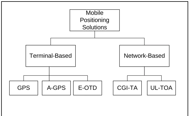
2.3.1 Positioning techniques for Cellular Phones
Mobile Positioning
Solutions
Network-Based Terminal-Based
GPS A-GPS E-OTD CGI-TA UL-TOA
Figure 2.1 Current Mobile Positioning Technologies
In June 1996, the Federal Communications Commissions (FCC) of USA had mandated a ruling that requires all mobile network operators in USA to provide location information on all calls to “E911”, referred as Wireless E-911 [2].
Research conducted by the American telecommunications research consultancy, Strategy, has found a quarter of potential location customers are interested in the
emergency services being able to automatically reveal their physical location [3]. Over the last few years, there have been significant technology developments for mobile location services support in wireless network. However, most location based services are based on GSM network standard. Since GPRS technology has been unfolded and keeps progressing, deploying mobile positioning on GPRS bearer provides much more benefits than GSM.
2.3.1 Global Positioning System (GPS)
GPS consists of 24 U.S. Government satellites encircling the earth, plus three back-ups in the air, which transmit a constant data signal; any device tuned into its frequency receives this signal. Most people will be familiar with 'classic' GPS technology, such as the personal devices that are now widely available and used in activities such as yachting and hiking as well as vehicle navigation systems. GPS now can achieve around 5m to 40m accuracy provided there is a clear view of the sky.
2.3.2 Assisted-Global Positioning System (A-GPS)
The main drawback of GPS is that satellite signals are relatively weak and may not provide adequate coverage to all environments. The GSM network can provide assistance information that gives integrated GPS receivers better coverage than
standalone GPS receivers. A-GPS or network assisted GPS uses fixed GPS receivers or location measurement units that are placed at regular intervals, about 300 km to collect assistance data. Assistance data makes it possible for the receivers to make timing measurements from the satellites without having to calculate the location. With satellite ephemeris and differential GPS correction provided by location measurement units, accuracy within 10m to 20m will be achieved.
2.3.3 Enhanced Observed Time Difference (E-OTD)
125m and not reliant on weather. E-OTD is becoming the de facto standard for Enhanced-911 Phase II implementation among U.S.
2.3.4 Cell Global Identity + Timing Advanced (CGI+TA)
The CGI identifies the cell in which the mobile terminal is located. A cell can be a circular or triangular sector. The TA parameter is an estimate of the distance, in
increments of 550m, from the mobile terminal to the base station. The accuracy depends on the size of the cell and varies from 10m (a micro cell in a building) to 500m (in a large outdoors macro cell). The estimated location is reported in terms of longitude, latitude and an uncertainty shape within which the mobile terminal located. For services that require proximity, this is the inexpensive and useful method.
2.3.5 Uplink Time of Arrival (UL - TOA)
UL-TOA works similarly as E-OTD, the difference being that UL-TOA data is measured. The base station of UL-TOA measures the time of arrival of a signal from a mobile
terminal. The base stations note the time difference and combine it with absolute time reading using GPS absolute time clocks. The UL-TOA positioning method works with all existing mobile terminals or legacy terminal but needs costly monitoring equipments to be installed virtually at all base station. Accuracy typically varies between 50m (rural) and 150m (urban).
2.4 Case Study : Enhanced – 911, Matsushita UTMS Emergency Call System
The most similar systems that exist or being developed currently in the market are the E-911 from United States and the Matshusita’s UTMS Emergency Call System.
2.5.1 Enhanced – 911
The FCC from USA had mandated that all mobile network operators in USA must provide location information on all calls to 911 [2]. The FCC mandated that by 1 October 2001, all wireless 911 calls must be pinpointed within 125 meters, 67% of the time. The purpose of E-911 is similar to EHS, to improve the ability and reliability of wireless emergency services. There are a number of rules and regulation regarding system E-911 to make the emergency calling system more reliable and secure. Since E-911 is strongly supported by both government and private organizations, the system is nearly perfect in the sense of functionality and deployment. However, E-911 is available for subscribers in USA only.
2.5.2 Matsushita UTMS Emergency Call System
2.3 Securing Wireless Mobile Computing
The convergence of mobile communication networks and Internet has enabled numerous ubiquitous Internet applications to be developed; m-commerce for example is the most popular. Security issues in the ubiquitous environment include confidentiality,
authentication, integrity, authorization, non-repudiation, and accessibility [Security issues in Mobile eCommerce]. Depending on the type of data and the cost of possible loss, modification, and stolen data, a security strategy must be devised and implemented.
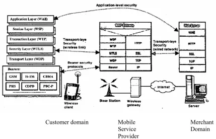
The use of wireless infrastructure such as in m-commerce application as illustrate in figure 2.2 may involve several parties; customer domain, mobile service provide and merchant domain [Security issues in Mobile Commerce using WAP]. Securing such an application can be achieved by deploying different levels of security mainly at bearer, transport and application level [Securing wireless Data: System Architecture
Challenges] as illustrated by figure 1. The bearer level provides network access domain security, which include user authentication, basic confidentiality and integrity. At bearer level, wireless network security is inefficient because it is easily hacked even though network access domain security is imposed [Securing wireless data: system
architecture challenges].
Transport as well as application level/layer security issues can be addressed by mobile middleware such as WAP. WAP provides security at transport level using Wireless Transport Security Layer (WTLS), [Ghosh and Swaminatha, “M-commerce Security”, Communications of the ACM, Feb 2001], which is similar to SSL in wired Internet. The end-to-end security issues are important in ubiquitous environment as multiple networks, devices, applications and software will exist and inter-operate. Secure WAP-based application at transport level is normally designed as a two stages model. At the first stage application will be encrypted from mobile device to WAP gateway, then decrypted and encrypted again into SSL between the gateway and the Web server. Decrypted data from WTLS cause the data to be in a clear text form, this present a
Since WAP version 1.2.1 does not necessarily result in an end-to-end security [Wired vs Wireless Security:The Internet, WAP, and iMode for E-Commerce], other
technology should be chosen.
Application layer security provides application-to-application and
application_user-to-application_user protection. It also enables additional security function not available at lower layer such as non-repudiation to be employed.
Figure 2.2: Security Protocol in a wireless data network [Securing wireless security data : system architecture challenges]
Customer domain Mobile Merchant
Service Domain
CHAPTER 3
METHOOLOGY
3.1 Introduction
This chapter describes the software process model adopted during the project
development. The hardware and software used during the project development are also presented. At the end of the chapter, we state some assumptions and limitations of the research.
3.2 Development Model
Development model used for developing EHS is Evolution Prototyping. The processes including developing trial system or experiment in short time sequence for evaluating by end users. In other words, prototype is an early version of a system or some of its functional parts that can be examined by end users. The purpose of this method is to detail and define system model interactively until user’s requirements were met.
3.2.1 Requirement Prototyping
3.2.2 Evolution Prototyping
Evolution prototyping is a system development methodology that can be fully
implemented. It used the similar techniques as requirement prototyping, except evolution prototype would not be thrown away. Prototype developed will be reconstructed to meet user’s specifications from time to time until a real system completed.
The objective of this method is to produce a functional system for end user. Starting from user’s requirements, prototype was built and followed by user’s evaluation until user’s specifications were met. Phases of evolution prototyping methodology are listed as below:
i. Determining user’s and system requirements:
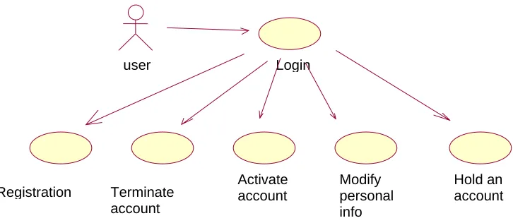
This phase clarifies fundamental requirements of user and system. User’s requirements of EHS are determined through brain storming, case studying and reviewing users’ opinion. The core user’s requirements are user friendliness, sufficient yet consistent information and effective error handling. EHS is model using UML technique as illustrated in figure 3.1, 3.2 and 3.3. We identified users to the systems to be the individual reporting the emergency and the professional (emergency personnel).
Figure 3.1: Use case for web portal module
user Login
Modify personal info Registration Terminate
account
Activate account
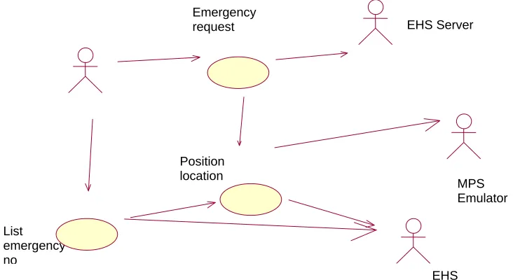
Figure 3.2: Use case for wireless module (end user)
Position location
List emergency no
EHS database
MPS Emulator Emergency
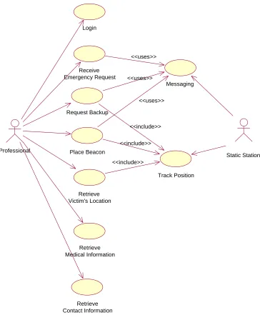
Figure 3.1: Use case diagram of Professional module
ii. Developing functional prototype:
A workable prototype system is developed based on requirements. The prototype may be immature but contains all the basic functions defined. The prototype is developed modularly based on object-oriented concepts. The modules include
Login
Retrieve Medical Information
Retrieve Contact Information
Receive Emergency Request
Retrieve Victim's Location
Place Beacon Static Station
Professional
Messaging <<uses>>
<<uses>>
Track Position <<include>>
<<include>> Request Backup
<<uses>>
user’s data management, positioning, messaging and Servlet handling. The distinguishing modules are integrated to furnish a functional system. The prototype is released to acquire user’s feedback. The system development is explained in section 4.3.
iii. Examining and evaluating functional prototype.
Execute and analyze the prototype to ensure that it fulfills the requirements defined. Sample data is input and the output is examined. The system
implementation is detailed in chapter iv. The prototype is then evaluated in terms of performance, stability and security. The analysis is discussed in section 5.5.
iv. Defining information required and modifying system.
If the prototype is rejected, the loop of the development will be restarted. Before restarting the loop, every method of the system is debugged to determine and fix all possible frauds.
3.4 Hardware Requirements
The most important hardware is PC or workstation to act as Server. Server is responsible for request and response handling, positioning and data management. The client device can be genuine device or emulator.
3.4.1 Server
PC or workstation with a specification: Pentium III 500 MHz processor or above can be used to serve as Web server, database server and application server. High
for storage. More processing power, memory and storage mean the system can support more users.
3.4.2 Client
Java-enabled mobile phones supporting GPRS transmission are ideal to be employed as client devices. EHS is a real time and interactive application based on J2ME platform and GPRS transmission, mobile phone with above features is necessary for the best performance. The clients are simulated using software due to expensive cost.
3.4.3 Mobile Positioning Center
The positioning gateway works as mediation device between PLMN and location service client. The MPC is responsible for revealing user’s physical location using specific positioning procedure. MPC can be simulated via software. MPC provides many benefits including security, independent of positioning procedures, free, support standard phones and easy to develop using provided API.
3.4 Software Requirements
3.4.1 Java™ 2 Software Development Kit (J2SDK) v1.4.0
Java programming provides portabilty and security. Since Java is object-oriented and platform independent, it is easier to develop Java application. Java is popular and evolving as a powerful programming language covering every requirements of
developers. Free JDK can be reviewed and downloaded at [9].
3.4.2 JavaTM 2 Micro Edition (J2ME) Wireless Toolkit 1.0.4
J2ME is specially designed for targetting handheld and embedded market. J2ME also provides security measurements via KSSL package. Since EHS is a mobile phone application, J2ME is ideal for developoing EHS. As JDK 2, J2ME toolkit is offered by Sun Microsystems without any charge at [15].
3.4.3 Forte For Java ME (Mobile Edition)
Forte For Java is an additional software package for J2ME. Forte provides a modular environment to increase application development productivity by enabling ability to edit, compile and execute Java application. Application development in J2ME become easier using Forte [16].
3.4.4 Ericsson MPS SDK 5.0
3.4.5 WMA Reference Implementation (RI)
Sun Microsystems has come up with a WMA reference implementation (RI) for PC emulators so that developers can create WMA applications independent of any actual phone or live network. The RI provides a transport mechanism that emulates SMS over the host PC's TCP/IP ports. All SMS messages are routed as datagram messages to host ports specified by the RI's runtime properties [13].
3.4.6 Windows 98, 2000, XP
Commonly used operating system, Windows is used as the main platform for project development. Since most software and emulators are supported by Windows OS, project development is much easier by eliminating complicated OS reconfiguration.
3.4.7 MySQL Database Server
The MySQL database server is the world most popular open source database. Its standard architectures makes it fast and easy to customize. An extra driver is required to communicate with MySQL database server using JDBC. [21]
3.4.8 Orion Application Sever
3.5 Assumptions
The EHS project involves several most updated technologies such as mobile positioning, GPRS, Java Servlet and mobile computing. Thus, some assumptions must be made to fully implement EHS system due to instability of the technologies:
i. Mobile phone supports MIDlet provisioning which capable of browsing, locating, transferring and installing a MIDlet suite on the device [11].
ii. MPC will provide comprehensive and accurate location information based on signal sent by subscribers.
iii. The normal users and professionals have already registered for EHS. In other words, database of EHS has contained their accounts and data.
iv. Location services are provided by the GPRS service providers.
3.6 Limitations
Despite the potential and capabilities of EHS, it remains constrained by the following limitations:
i. Lack of government rules and regulations to protect the reliability of EHS services. EHS is exposed to the misuse of some users by simply making fallacious request.
of 5-40 meters. Accuracy can be enhanced by deploying Bluetooth technology but not reasonable in cost. Thus, direct communication line is established between user and responding professional.
iii. Mobile data transmission is always a problem for rural area subscribers. Deploying EHS in rural area needs more adaptations and modifications.
iv. Battery life
Unfortunately, battery technology does not progress on par with mobile phone technology. Processing high bandwidth data certainly demands more battery power. User will be burden and frustrated if the battery of handset need to be charged in very short interval. This issue should remains as the main problem to be driven off.
CHAPTER 4
DESIGN AND IMPLEMENTATION
4.1 Introduction
In this chapter we present the design and integrated implementation of Emergency Handling System.
4.2 Architectural design
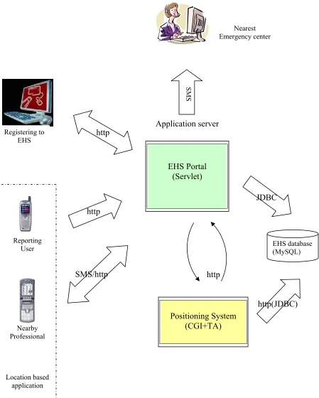
EHS is designed based on WWW client/server model. End users may activate the client process, which can be a midlet or web application. Where as the sever side consists of several sub-components; EHS portal, positioning system and database. Architectural design of EHS is shown in Figure 4.1. EHs portal plays an important role in EHS system; it is the main engine that controls the interaction between end users, the positioning system and database via http or SMS protocol.
4.2.1 EHS Portal
SMS/http Reporting
User
Nearby Professional
Location based application
Application server
http
http(JDBC)
Figure 4.1: Architectural design of EHS
EHS database (MySQL) Nearest
Emergency center
Registering to EHS
Positioning System (CGI+TA) http
http
SMS
JDBC EHS Portal
MIDP mandates a HTTP communication protocol which is suitable for MIDP client to interact with Servlet. A client-server paradigm offloads complicated
computation from the limited capabilities of the MIDP device to more capable server environment. In EHS, sub-modules that require managing client-server request and response are mainly retrieving location information, contact and medical information. The core and complicated task is processed at server side while the client simply handles input and output.
Some general settings have to be done before a client can communicate with server processes. The settings include setting request method and HTTP headers:
//url is changed according to process called
String url = “http://127.0.0.1/servlet/getContactInfo;”
HttpConnection conn = (HttpConnection) Connector.open (url); conn.setRequestMethod(HttpConnection.POST);
// or conn.setRequestMethod(HttpConnection.GET); conn.setRequestProperty(“User Agent”,
“Profile/MIDP-1.0 Configuration/CLDC1.0 ”); conn.setRequestProperty(“Content-Language”, “en-US”);
conn.setRequestProperty(“Accept”, “application / octet-stream ”); conn.setRequestProperty(“Connection”, “close”);
// set this is request method is POST
conn.setRequestProperty("Content-Type", "application/x-www-form-urlencoded");
After the initial settings, the application or MIDlet is ready to communicate with server. The task includes composing request and listening for response. All
communications between client and server are based on stream or binary format. The structure of the codes is described as follow:
//…
// composing request
DataOutputStream os = new DataOutputStream(conn.openOutputStream( )); os.write(data); // write request into output stream
os.flush(); os.close();
// read response from server via input stream byte [] data;
int len = conn.getLength();
InputStream in = conn.openInputStream( ); if (len != -1){
int total = 0;
data = new byte[len]; while (total < len) {
total += in.read (data, total, len - total); }
} else {
ByteArrayOutputStream tmp = new ByteArrayOutputStream( ); int ch;
while ( (ch = in.read( )) != -1) { tmp.write (ch);
}
data=tmp.toByteArray(); }
in.close();
// …… process input based on output requirements.
At the server side, request and response are handled by Servlet. The Servlet gets the parameters from the request body. The Servlet then sets an output stream and sends the data back to requesting client. The structure of the process is coded as follow:
// an example of get user’s contact information servlet
// the servlet gets msisdn as parameter and search for user’s contact information from // database record
public void doGet(HttpServletRequest req, HttpServletResponse res)throws ServletException, IOException {
String msisdn= req.getParameter("msisdn") ; PrintWriter out = res.getWriter();
try{ Class.forName("org.gjt.mm.mysql.Driver"); theConnection = DriverManager.getConnection("jdbc:mysql://127.0.0.1:3306/ehs", "",""); Statement theStatement=theConnection.createStatement();
String sqlQuery = “select * from contact where mobileTel='"+msisdn+"'"; ResultSet theResult=theStatement.executeQuery(sqlQuery);
//Fetch all the records and print in table while(theResult.next()){
out.print(theResult.getString("name"));
out.print("MTEL" + theResult.getString("mobileTel")); out.print("HTEL" + theResult.getString("homeTel")); out.print("ADD" + theResult.getString("address"));
out.print("EMNAME" + theResult.getString("egContact")); out.println("EMTEL" + theResult.getString("egTel")); }
theResult.close();//Close the result set theStatement.close();//Close statement
theConnection.close(); //Close database Connection }catch(Exception e){
out.println(e.getMessage());//Print trapped error. }
}
Communication between users of EHS is based on J2ME Wireless Messaging API. Wireless Messaging API (WMA) is an optional package enabling applications to send and receive short text message or binary message over wireless environment. Since the application is not implemented in real network, WMA Reference Implementation (RI) is used to simulate the wireless messaging environment.
format. If a professional places a beacon, the beacon message will be broadcast to nearby user as wireless message as well.
The sending and receiving of wireless short message defined by WMA is fairly simple. The MIDlet that successfully opens a message connection will be eligible to send message to designated user. The destination of wireless message sent is based on phone number and port:
// establishing message connection at port 9999 String url = “sms://9999” ;
MessageConnection conn = (MessageConnection) Connector.open(url); public void sendSms (String message, String destination){
try {
TextMessage msg = conn.newMessage (conn.TEXT_MESSAGE); msg.setPayloadText(message);
msg.setAddress (destination); conn.send(msg);
} }
conn.close();
The fundamental sending method above can be amended to broadcast message. The only change is from single destination to a string of destination addresses:
// establishing message connection at port 9999 String url = “sms://9999”;
MessageConnection conn = (MessageConnection) Connector.open(url); public void broadSms (String message, Vector destinations){
try {
TextMessage msg = conn.newMessage (conn.TEXT_MESSAGE); msg.setPayloadText(message);
for (Enumeration e = destinations.elements() ; e.hasMoreElements() ;) { msg.setAddress ((String) e.nextElement());
} } }
conn.close();
The receiving message process is handled by an extra thread simultaneously. The receiving method will block all the processes until a message is received. The connection for receiving message is opened mainly based on port number:
// establishing message connection at port 8888 String url =”sms://8888”
MessageConnection conn = (MessageConnection) Connetor.open (url); public void run (){
while (true){ try{
Message receiveMessage = conn.receive( ); //blocks until receive message if (receiveMessage instanceOf TextMessage){
TextMessage msg = (TextMessage) receiveMessage; String message = msg.getPayloadText();
// show, broadcast or forward message…… }
} } }
4.2.2 Location Processing
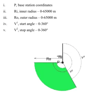
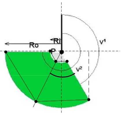
This module is the foremost component of the EHS system. The fundamental position data is provided by MPC taken from Ericsson’s Mobility World [1]. The solution of MPC is based on CGI+TA technique and the position data generated consists of:
iv. V1, start angle – 0-360° v. V2, stop angle – 0-360°
Figure 4.3.2: Position Data from MPC
The user is expected to stay within the arc area. The next step is to convert the position data to readable location information. The following steps explain the processes:
i. Get the position data, including base station’s coordinates, inner and outer radius, start and stop angle. (Refer Figure 4.24)
ii. Calculate the coordinates of several points within the arc area using trigonometry formula. The detail of the calculation is explained later.
iii. Match the coordinates of the points determined with coordinates assigned for each location. The location which has been matched for the most time
indicates the user’s location.
This module is the foremost component of the EHS system. The fundamental position data is provided by MPC taken from Ericsson’s Mobility World [1]. The solution of MPC is based on CGI+TA technique and the position data generated consists of :
i. P, base station coordinates ii. Ri, inner radius – 0-65000 m iii. Ro, outer radius – 0-65000 m iv. V1, start angle – 0-360° v. V2, stop angle – 0-360°
Figure 4.16 Position Data from MPC
The user is expected to stay within the arc area. The next step is to convert the position data to readable location information. The following steps explain the processes:
iv. Get the position data, including base station’s coordinates, inner and outer radius, start and stop angle. (Refer Figure 4.24)
vi. Match the coordinates of the points determined with coordinates assigned for each location. The location which has been matched for the most time
indicates the user’s location.
4.3.1.1 Coordinates Calculation
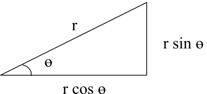
Based on the position data, an arc is built for representing user’s position. The position data is to be matched with the related map to obtain user’s location. By applying trigonometry formula, coordinates for several matching points within the arc area can be determined, refer Figure 4.25 and Figure 4.26.
Figure 4.17 Trigonometry Formula
The matching points (L1, L2, L3, L4, L5 and L6) within the arc area:
ө
r
r cos
ө
Figure 4.18 Matching Points within arc Area
The coordinates of a specific point is calculated as below:
For instance, the coordinates (x,y) of L1 is calculated as follow: Coordinate x of a specific point
= coordinate x of P (base station) ± distance from vertical line = xp ± distance from vertical line
= xp ± r (cos ө)
Coordinate y of a specific point
= coordinate y of P ± distance from horizontal line = yp ± distance from horizontal line
Coordinates x of L1 = xp + Ro [cos (V1 – 90°)]
= xp + Ro [cos V1 cos 90° + sin V1 sin 90°]
= xp + Ro [cos V1 . 0 + sin V1 . 1]
= xp + Ro sin V1
Coordinates y of L1 = yp – Ro [sin (V1 – 90°)]
= yp – Ro [sin V1 cos 90° - cos V1 sin 90°]
= yp – Ro [sin V1 . 0 – cos V1 . 1]
= yp + Ro cos V1
There is an important condition that will affect the calculation that is in which sector of the circle the point is located. However, a generic formula can be derived without considering where the point is located:
x = xp + r sin ө y = yp + r cos ө
To examine the formula, the distinguishing points from all different sectors are calculated.
Table 4.7 Coordinates Calculation Diagram Calculation
x = xp + r cos (90° - ө)
= xp + r (cos 90° cos ө + sin 90° sin ө)
= xp + r (0 . cos ө + 1. sin ө)
= xp + r sin ө
y = yp + r sin (90° - ө)
= yp + r (1 . cos ө + 0 . sin ө)
= yp + r cos ө
x = xp + r cos (ө - 90°)
= xp + r (cos ө cos 90° + sin ө sin 90°)
= xp + r (cos ө . 0 + sin ө . 1)
= xp + r sin ө
y = yp - r sin (ө - 90°)
= yp - r (sin ө cos 90° - cos ө sin 90° )
= yp - r (sin ө . 0 - cos ө. 1)
= yp + r cos ө
P
r
x y
x = xp - r cos (270° - ө)
= xp - r (cos 270° cos ө + sin 270° sin ө)
= xp - r (0 . cos ө + (-1) . sin ө)
= xp + r sin ө
y = yp - r sin (270° - ө)
= yp - r (sin 270 cos ө - cos 270° sin ө )
= yp - r ((-1) . cos ө - 0. sin ө)
= yp + r cos ө
x = xp - r cos (270° - ө)
= xp - r (cos 270° cos ө + sin 270° sin ө)
= xp - r (0 . cos ө + (-1) . sin ө)
= xp + r sin ө
y = yp - r sin (270° - ө)
= yp - r (sin 270 cos ө - cos 270° sin ө )
= yp + r cos ө
As long as the angle (V1, V2) and radius (Ri, Ro) is provided, a generic formula can be applied to obtain the coordinate of a specific matching point. The matching points are to be compared with the coordinates covering a specific location. For this prototype, only six matching points are going to be compared. The accuracy of the map matching will increased if more matching points are determined and compared. The algorithm of calculating the coordinates (refer 4.18) is as follow:
// xp = base station’s coordinate x
// yp = base station’s coordinate y
// Ri = inner radius // Ro= outer radius // V1 = start angle // V2 = stop angle
xL1 = xp + Ro sin V 1
yL1 = yp + Ro cos V 1
xL2 = xp + Ri sin V 1
yL2 = yp + Ri cos V 1
xL3= xp + Ro sin [ V1 + (V2-V1)/2 ]
yL3= yp + Ro cos [V1 + (V2-V1)/2 ]
xL4= xp + Ri sin [ V 1
+ (V2-V1)/2 ] yL4= yp + Ri cos [V1 + (V2-V1)/2 ]
xL5= xp + Ro sin V 2
yL5= yp + Ro cos V
2
xL6= xp + Ri sin V 2
yL6= yp + Ri cos V
4.3.1.2Map Matching
To translate the position data to understandable location information, the matching points are taken to compare with coordinates of the areas. The location
information is predefined and stored in database, refer Table 4.21. The name of a location is returned if the coordinate of the matching point matches the area. The snippet of the map matching is shown as follow:
public String mapLocation ( String coordinateX, String coordinateY){
/*
//To make connection to database
// Class.forName("org.gjt.mm.mysql.Driver"); // connetion theConnection =
DriverManager.getConnection("jdbc:mysql://127.0.0.1:3306/ehs", "",""); */
//SQL Statement to retrieve location that covers a point.
//(upLeftX, upLeftY) and (lowRightX, lowRightY) define an area String sqlQuery ="SELECT name FROM Location WHERE " +"upLeftX <='"+mPointX+"' AND " +"upLeftY >='"+mPointY+"' AND "
+"lowRightX >='"+mPointX + "' AND " + "lowRightY <='"+mPointY+"'"; try{
//insert query result or each record of location into vector while (theResult.next()){
s = theResult.getString (“name”); }
}
theResult.close(); theStatement.close(); return s;
}
The location’s name returned for each matching point is collected and compared. The location which matched for the most time is estimated as user’s location. The comparison process is shown as follow:
// the returned results are collected in Vector // records are compared among each other.
// the most referred location’s name is decided as user’s location
public String getLocation (Vector locations){
// Vector “locations” is an array of location names
// Vector “locations” is cloned to prevent any changes to the original Vector Vector temp = locations.clone();
while (! temp.isEmpty()){ counter = temp.size();
String str = temp.firstElement(); while(temp.contains(str){ temp.remove(str); }
temp.trimToSize();
counter = counter – temp.size(); if (counter > max){
max = counter; location = str; }
return location; }
4.2.3 Security Implementation of EHS
Figure 4.xx illustrates the various layers of employing security protocol in order to achieve secure wireless data communications [Figure 1, Securing wireless data: system architecture challenges]….
EHS require higher level security mechanism due to inefficiency of network access domain security. In addition, EHS adopts end-to-end security to ensure secure data transmission between end user device and server at the same time avoiding the possibility of WAP gap problem. Hence, EHS is implemented by deploying Java technology. Java provides Cryptography classes in a package called Bouncy Castle Crypto API. The package is a lightweight API of equivalent to JCE 1.2.1 and it provides authentication tool version 1 and version 3 X.509. EHS deployed MD5 hashing
Figure to illustrate the security process of EHS
CHAPTER 5
5.1 Introduction
5.2 Result
There are several core modules that collaborate with each other to accomplish a task, namely location processing, Servlet handling and wireless messaging.
5.2.1 EHS Portal
Figure 5.1: Management of user account
start
end
Login regsitration
Main page Activate account
Edit user profile Deactivate account
5.2.2 Requesting for an emergency assistance
A user can easily send a distress message for a specific assistance simply by selecting the menu without having to communicate with an intermediary as in the manual 999
emergency services. Prior to making an emergency call, the user is required to login once and the session will be kept alive until deactivated by the user.
Figure 5.2: Sending a distress message
5.3 Professional module
The application server will forward the distress message sent by a victim to the professional nearby the incident vicinity. The professional is appointed to receive
emergency request, retrieve victim-related information, request backup and place beacon.
5.3.1 Login
The login process will determine user’s authority and accessibility. Invalid user will be prompted an error message whereas valid user will proceed to system main menu. The login process is illustrated in Figure 5.3 below:
User login to EHS Select emergency
service Display nearest station Login
succeed
Figure 5.3 Login Process
5.3.2 Handling emergency request and reply
The professional will receive an alert indicating emergency request from nearby victim. The emergency request is sent as wireless message format. The professional has to check his or her message inbox to read the emergency message. The professional can choose to reply or retrieve victim’s location, contact and medical information. The process is illustrated in Figure 5.3.
a) Login Succeed
Alert
Check Message
view
Menu Reply
view location
contact info
medical info
Figure 5.4 Emergency Request and Reply
5.3.3 Request Backup
request backup
view location view
contact info send
request
Figure 5.5 Request Backup
5.3.4 Place Beacon
Figure 5.6 Place Beacon
5.4 Mobile Network Simulation
EHS system was tested on simulated environment, whereby MPC Map Tool creates simulated mobile network for use with the MPC Emulator. By loading or scanning a map, defining phone routes and population areas, MPC Map Tool automatically generates a mobile network that used to demonstrate positioning methods.
This project uses the map of Johor Bahru to simulate the mobile network (refer Appendix C). The population areas are defined approximately as dense urban, urban, suburban or rural area. To enable detection of mobile phone users, the phone routed are to be declared. The phone routes represent mobile phone user’s movement in the cellular network.
After declaring the routes and areas, a cell pattern is generated as illustrated in Figure 5.1. MPC Map Tool calculates the location of the base stations and the cell shape to match the capacity demand in the area. A cell is represented by a hexagon with the base station as a red dot.
CHAPTER 6
DISCUSSION, CONCLUSION AND RECOMMENDATIONS
6.1 Introduction
6.2 Discussion
6.3 Conclusion
REFERENCES
“Planning and Responding to Workplace Emergencies”, Osha Fact Sheet,
http://www.osha.gov/OshDoc/data_General_Facts/factsheet-workplaceevergencies.pdf
callflow.gif http://north-van.rcmp-grc.gc.ca/e911.htm
“WAP Security”, http://www.perfectxml.com/Conf/Wrox/Files/howell1text.pdf “Understanding WAP Security”, http://www.techsupportalert.com/pdf/b1423.pdf “ATTACKS AGAINST THE WAP WTLS PROTOCOL”,
http://www.cc.jyu.fi/~mjos/wtls.pdf.
“Security Issues in Mobile Commerce using WAP". White Paper WPSE-R4-001,
Phone.com, Jan. 2000, http://www.dat.ruc.dk/~ncjuul/papers/BledWAP3.pdf
“Wired versus Wireless Security:The Internet, WAP and iMode for E-Commerce
”, http://www.acsac.org/2001/papers/61.pdf
Need to be downloaded
http://security.dso.org.sg/publications/wireless/WAP_security.pdf
“Security in a Wireless Mobile Health Care System”, http://www.research.att.com/~rjana/Marti-Delgado.pdf
“Secure Mobile e-Client”
http://www.intel.com/business/bss/solutions/blueprints/pdf/utimaco_eclient.pdf “ENSURING MOBILE SECURITY WITH AVANTGO TECHNOLOGY
“http://www.avantgo.com/doc/mbiz/AvantGoMobileSecurityWhitePaper.pdf
“Wireless Security:
http://www.stratvantage.com/publications/geneerwirelesssecurity.pdf
“Windows Mobile-Based Devices and Security: Protecting Sensitive Business Information”, http://techlibrary.wallstreetandtech.com/data/
Wired versus wireless security: the Internet, WAP and iMode for E-commerce Ashley, P.; Hinton, H.; Vandenwauver, M.;
Computer Security Applications Conference, 2001. ACSAC 2001. Proceedings 17th Annual , 10-14 Dec. 2001
Pages:296 – 306
2 The advantages of elliptic curve cryptography for wireless security Lauter, K.;
Wireless Communications, IEEE [see also IEEE Personal Communications] , Volume: 11 , Issue: 1 , Feb. 2004
Pages:62 – 67
3 Facing the challenge of wireless security Miller, S.K.;
Computer , Volume: 34 , Issue: 7 , July 2001 Pages:16 – 18
4 The advantages of elliptic curve cryptography for wireless security Lauter, K.;
Wireless Communications, IEEE [see also IEEE Personal Communications] , Volume: 11 , Issue: 1 , Feb. 2004
5 Securing wireless data: system architecture challenges Ravi, S.; Raghunathan, A.; Potlapally, N.;
System Synthesis, 2002. 15th International Symposium on , 2-4 Oct. 2002 Pages:195 – 200
6 System design methodologies for a wireless security processing platform Ravi, S.; Raghunathan, A.; Potlapally, N.; Sankaradass, M.;
Design Automation Conference, 2002. Proceedings. 39th , 10-14 June 2002 Pages:777 – 782
7 Performance of a handset-assisted positioning method for GSM Villier, E.; Lopes, L.; Ludden, B.;
Vehicular Technology Conference, 1999 IEEE 49th , Volume: 3 , 16-20 May 1999 Pages:1967 - 1972 vol.3
8 Cellular position location techniques a parameter detection approach Estrada, R.; Munoz-Rodriguez, D.; Molina, C.; Basu, K.;
Vehicular Technology Conference, 1999 IEEE 49th , Volume: 2 , 16-20 May 1999 Pages:1166 - 1171 vol.2
Mobile positioning technologies in cellular networks: an evaluation of their performance metrics
Adusei, I.K.; Kyamakya, K.; Jobmann, K.;
MILCOM 2002. Proceedings , Volume: 2 , 7-10 Oct. 2002 Pages:1239 - 1244 vol.2
9 2 Mobile positioning technologies and location services Wang, S.S.; Green, M.; Malkawi, M.;
Radio and Wireless Conference, 2002. RAWCON 2002. IEEE , 11-14 Aug. 2002 Pages:9 – 12
10 GSM mobile positioning simulator Wylie-Green, M.P.; Wang, P.;
IEEE , 10-11 April 2000 Pages:5 pp.
11 GSM-based mobile positioning using WAP Wong, C.L.C.; Lee, M.C.; Chan, R.K.W.;
Wireless Communications and Networking Conference, 2000. WCNC. 2000 IEEE , Volume: 2 , 23-28 Sept. 2000
Pages:874 - 878 vol.2
12 Mobile positioning technologies and location services Wang, S.S.; Green, M.; Malkawi, M.;
Radio and Wireless Conference, 2002. RAWCON 2002. IEEE , 11-14 Aug. 2002 Pages:9 – 12
13 The security issues and countermeasures in Mobile IP Wang Haitao; Zheng Shaoren;
Info-tech and Info-net, 2001. Proceedings. ICII 2001 - Beijing. 2001 International Conferences on , Volume: 5 , 29 Oct.-1 Nov. 2001
Pages:122 - 127 vol.5
14 153 Authentication of mobile users Molva, R.; Samfat, D.; Tsudik, G.;
Network, IEEE , Volume: 8 , Issue: 2 , March-April 1994 Pages:26 – 34
15 Secure mobile commerce
Schwiderski-Grosche, S.; Knospe, H.;
Electronics & Communication Engineering Journal , Volume: 14 , Issue: 5 , Oct. 2002
Pages:228 – 238
16 Security considerations for distributed Web-based e-commerce applications in Java
Lindquist, T.E.;
System Sciences, 2002. HICSS. Proceedings of the 35th Annual Hawaii International Conference on , 7-10 Jan. 2002
17 “A taxonomy of indoor and outdoor positioning techniques for mobile location services”. ACM SIGecom Exchanges archive
Volume 3 , Issue 4 Winter, 2003 table of contents Mobile commerce
Pages: 19 - 27
Year of Publication: 2002
18 A flexible framework for using positioning technologies in location-based services
Ranchordas, J.; Lenaghan, A.;
EUROCON 2003. Computer as a Tool. The IEEE Region 8 , Volume: 2 , 22-24 Sept. 2003 “Location Awareness and LBS Part1”,
http://www.symbian.com/developer/techlib/papers/messaging/LocalAwareness_LB S_01.pdf
19 Developing location-based services from a GIS perspective Stojanovic, D.H.; Djordjevic-Kajan, S.J.;
Telecommunications in Modern Satellite, Cable and Broadcasting Service, 2001. TELSIKS 2001. 5th International Conference on , Volume: 2 , 19-21 Sept. 2001 Pages:459 - 462 vol.2
20 Using SMS to deliver location-based services Krishnamurthy, N.;
Personal Wireless Communications, 2002 IEEE International Conference on , 15-17 Dec. 2002
Pages:177 – 181
21 Wireless location privacy protection Schilit, B.; Hong, J.; Gruteser, M.;
Computer , Volume: 36 , Issue: 12 , Dec. 2003 Pages:135 – 137
Communications Magazine, IEEE , Volume: 36 , Issue: 4 , April 1998 Pages:66 – 71
23 Juha Mynttinen, “End-to-end security of mobile data in GSM”, Seminar on Network Security, 2000, http://www.hut.fi/~jmynttin/netsec/paper.pdf
24 “Wireless Mobility Application Security in the Enterprise”,
http://www.vaultus.com/news/documents/WHITEPAPER_Security.pdf
25 Deitel et al, “Internet & World Wide Web: How to Program 2nd Edition”, Prentice Hall inc., 2002.
26 Elista Basita, “Mobile Emergency: The other 911”, http://www.wired.com/news/wireless
27 Nicky Boertien and Eric Middlekoop, “Location Based Services”,
https://doc.nl/dscgi/ds.py/Get/File-23319/location_based_services.pdf, Virtuele Haven Consortium, May 2002.