University of Windsor University of Windsor
Scholarship at UWindsor
Scholarship at UWindsor
Electronic Theses and Dissertations Theses, Dissertations, and Major Papers
7-11-2015
Design of a Control System for a Reconfigurable Engine Assembly
Design of a Control System for a Reconfigurable Engine Assembly
Line
Line
Hamid Tabti
University of Windsor
Follow this and additional works at: https://scholar.uwindsor.ca/etd
Recommended Citation Recommended Citation
Tabti, Hamid, "Design of a Control System for a Reconfigurable Engine Assembly Line" (2015). Electronic Theses and Dissertations. 5329.
https://scholar.uwindsor.ca/etd/5329
This online database contains the full-text of PhD dissertations and Masters’ theses of University of Windsor students from 1954 forward. These documents are made available for personal study and research purposes only, in accordance with the Canadian Copyright Act and the Creative Commons license—CC BY-NC-ND (Attribution, Non-Commercial, No Derivative Works). Under this license, works must always be attributed to the copyright holder (original author), cannot be used for any commercial purposes, and may not be altered. Any other use would require the permission of the copyright holder. Students may inquire about withdrawing their dissertation and/or thesis from this database. For additional inquiries, please contact the repository administrator via email
Design of a Control System for a Reconfigurable Engine Assembly Line
By
Hamid Tabti
A Thesis
Submitted to the Faculty of Graduate Studies through the Department of Industrial and Manufacturing Systems Engineering
in Partial Fulfillment of the Requirements for the Degree of Master of Applied Science
at the University of Windsor
Windsor, Ontario, Canada
2015
Design of a Control System for a Reconfigurable Engine Assembly Line
By
Hamid Tabti
APPROVED BY:
______________________________________________
J. Wu, Outside Program Reader Electrical & Computer Science
______________________________________________ A. Djuric, Program Reader
Wayne State University, Cross-appointed to IMSE
______________________________________________
H. ElMaraghy, Advisor
Industrial & Manufacturing System Engineering
iii
DECLARATION OF ORIGINALITY
I hereby certify that I am the sole author of this thesis and that no part of this thesis has been published or submitted for publication.
I certify that, to the best of my knowledge, my thesis does not infringe upon anyone’s copyright nor violate any proprietary rights and that any ideas, techniques, quotations, or any other material from the work of other people included in my thesis, published or otherwise, are fully acknowledged in accordance with the standard referencing practices. Furthermore, to the extent that I have included copyrighted material that surpasses the bounds of fair dealing within the meaning of the Canada Copyright Act, I certify that I have obtained a written permission from the copyright owner(s) to include such material(s) in my thesis and have included copies of such copyright clearances to my appendix.
iv
ABSTRACT
Today’s automotive manufacturing environment is dynamic, not long ago,
plants produced engines for decades, with minor modifications warranting slight
manufacturing line rework. Conversely, today’s changing trends require machines
and complete engine line overhauls rendering initial setups obsolete. Automakers
compete to satisfy government regulations for best mileage and also lower
manufacturing cost, thus the adoption of Reconfigurable Manufacturing Systems
(RMS). Information Technology (IT) and Controls are growing closer with the line
of demarcation disappearing in manufacturing. Controls are benefiting from
opportunities in IT, hardware and software. Component-based software suitable for
RMS modularity and plug-and-play hardware/software components has gained
decades of popularity in the software industry. This thesis implements distributed
controls imbedding component-based technology and IEC 61311-3 function block
standard for automotive engine assembly, which will contribute to these
developments. The control architecture provides reconfigurability which is lacking
in current manufacturing systems. The research imbeds: 1- Reconfigurability -
Fitting RMS-designed hardware towards new manufacturing, 2- Reusability -
Building software library for reuse across assembly lines, and 3- Plug-and-Play -
v
DEDICATION
vi
ACKNOWLEDGEMENTS
First, I would like to express my sincere gratitude to Ford Motor Company
for their continuous and generous support to complete this Master thesis. Special
thanks go to Mr. Mike Bastian, Controls Manager at Ford Motor Company for his
support, help and interest in the research. The years I spent at the IMSE center of
the University of Windsor were a great enlightening learning experience for me. I
certainly refined my knowledge of manufacturing systems and acquired an edge to
explore research and development opportunities while applying my experience on
the reality of the plant floor against academic principles. The research in this
thesis was inspired by the organization needs and enhanced by academia’s
perpetual constructive feedback.
I would like to express my genuine gratitude to my supervisor, Dr. Hoda
ElMaraghy, and to my supervisory committee members, Dr. A.Djuric and Dr. J.
Wu. I believe that my supervisor provided me with her best of assistance, advice,
and guidance to getting my research done. Dr. ElMaraghy’s vision, experience,
and directions were essential to establish the major frame to this work. Special
thanks go to Dr.Waguih ElMaraghy as well, for support, help and constructive
criticism allowing me to stay the course of completing this research.
I am also very grateful to my collaboration all along with other researchers at the
IMSE laboratory. I had indeed the opportunity to work with highly talented and
extremely intelligent researchers, from whom I learned a lot. The combined
academic-industrial fertile research environment I worked in hosted the research
reported in this thesis
Finally I would like to thank my wife for patiently sacrificing her time as in
providing full attention to our five children, which in particular allowed me to stay
late at the university, after working hours and over weekends, progressing with my
vii
whom while away encouraged me to persevere in completing this degree. This
thesis is offered to my wife, my children, my late mother, my father, my siblings,
whom committed much of their time not to say their entire lives help shaping the
viii
Table of Contents
DECLARATION OF ORIGINALITY ... iii
ABSTRACT ... iv
DEDICATION ...v
ACKNOWLEDGEMENTS ... vi
LIST OF TABLES ... xi
LIST OF FIGURES ... xii
LIST OF ABBREVIATIONS/SYMBOLS ... xiv
1 Introduction ... 1
1.1 Engine Assembly Overview ... 1
1.2 Engine Assembly Layouts ... 1
A Single Loop Layout: ... 1
B Multiple Loops Layout: ... 1
1.3 Engine Assembly Station Types ... 3
A Manual Assembly Stations: ... 3
B Automatic Assembly Stations: ... 4
1.4 Engine Variants ... 5
1.5 Enablers for Reconfigurability in Engine Assembly Lines ... 6
1.6 Motivation for Research... 8
1.7 Objectives and Problem Statement ... 9
Literature Survey ... 10
2.1 Traditional Control Architectures ... 10
2.1.1 Centralized Architecture ... 10
2.1.2 Hierarchical Architecture ... 11
2.1.3 Heterarchical Architecture ... 11
2.2 Holonic Manufacturing Systems (HMS) ... 12
2.3 RMS Controls System State-of-the-art ... 14
2.3.1 Open Control Architecture Systems ... 14
ix
2.4.1 Object Oriented Programming (OOP): ... 15
2.4.2 Unified Modeling Language (UML) ... 15
2.4.3 Petrinets (PNs): ... 15
2.4.5 Agent-based methodology ... 16
2.5 Component-based Software Technology (CBS) ... 16
2.6 Industrial Control in Automotive Sector: State-of-the-art ... 17
2.7 Summary ... 18
3.1 System Engineering to Design Controls Software ... 20
3.2 Design Steps for Engine Assembly ... 21
3.2.1 Design of Assembly Process ... 21
3.2.2 Design of Mechanical Machinery and Tooling ... 22
3.2.3 Design of Controls Hardware System ... 22
3.2.4 Design of Controls Software System ... 23
3.3 Controls Software Design Process ... 25
3.3.1 Software Requirements Definition ... 26
3.3.2 Controls Hardware Identification ... 27
3.3.3 Control Software Design ... 28
3.3.4 PLC Functions in Production Machine ... 29
3.4 Component-based Software Technology ... 30
3.4.1 Software Components Definition ... 30
3.4.2 Software Component Characteristics ... 31
3.5 Summary ... 31
4. Component-based Approach to Machine Controls Software ... 32
4.1 Decomposition of Controls System ... 33
4.1.1 Decomposition of Controls System using Cladistics ... 34
A STEP 1 – Identification of Control System Components ... 34
B STEP 2 – Building DSM to Capture Data Relationships ... 35
C STEP 3– Cladogram Generation using Phylip Software ... 36
D STEP 4 – DSM Matrix Rearrangement ... 37
E STEP 5 – Calculation of Modularity Index ... 37
4.2 Conceptual Design of PLC Logic using Axiomatic Design ... 41
x
4.3 Control Logic Programming Language ... 44
4.4. Function Block Development ... 45
4.5 Function Block Testing ... 47
4.6 Machine Logic Testing ... 47
4.7 Engine Assembly General Controls Hardware ... 48
4.8 Formalization of Controls Software Modularity Method ... 49
4.9 Summary ... 49
5 Case Study 1: Manual Workstation Program Generation ... 50
5.1 Motor Control FB Development ... 50
5.2 Design Matrix for Motor Control FB ... 50
5.3 Motor Control FB Development ... 54
5.4 Manual Work Station Program Building ... 54
5.5 Case Study 2: Addition of Stop to Work Station ... 55
5.5.1 Re-configurability Capability ... 55
5.5.2 Addition of New Module to Machine ... 57
5.6 Summary ... 60
6 Conclusions ... 61
6.1 Contributions ... 62
6.2 Research Significance ... 62
6.3 Industrial Significance ... 63
6.4 Limitations ... 64
6.5 Future Work ... 64
REFERENCES/BIBLIOGRAPHY...65
APPENDICES ...72
Appendix A: Motor Control Flow Chart Figures ... 72
Appendix B: PLC Program for Manual Station in Figure 4.1 ... 74
Appendix C: PLC Program for Manual Station in Figure 5.8 ... 78
xi
LIST OF TABLES
Table 3.1: Hardware and Software Characteristic Requirements for RMS System
Table 4.1: BOM for Manual Work Station
Table 4.2: Original DSM Matrix
Table 4.3: Rearranged DSM Matrix
Table 4.4: Granularity Level 1
Table 4.5: Granularity Level 2
Table 4.6: Granularity Level 3
Table 4.7: Granularity Level 4
Table 4.8: Granularity Level 5
Table 4.9: Survey on Mechatronic Components in an Assembly Line
Table 5.1: Motor Control FB Decomposition FR1- DP1
xii
LIST OF FIGURES
Figure 1.1: Single Loop Assembly Line
Figure 1.2: Three-loop Engine Assembly Line
Figure 1.3: Manual Work Station
Figure 1.4:Automatic Assembly cell - Hirata Assembly Systems
Figure 1.5: Engine Variants through a Typical Engine Assembly Line
Figure 1.6: Enterprise PC Distributed Control System
Figure 1.7: Distributed Control System Hardware
Figure 2.1: Centralized Architecture System Sample
Figure 2.2: Hierarchical Controls System Sample
Figure 2.3: Heterarchical Controls System Sample
Figure 2.4: Holonic System Layout (Bussmann and Sieverding, 2001)
Figure 3.1: IEEE Vee Model for Software Systems Engineering Process
Figure 3.2: Network of PLCs in an Engine Assembly
Figure 3.3: Design Framework Extended from Yien and Tsang (1996)
Figure 3.4: Design Methodology Phases
Figure 3.5 PLC Rack Connected to Field Sensors and IT
Figure 4.1 Modular Design for Manual Workstation
Figure 4.2: Phylip Software and Cladogram Outputs
Figure 4.3: Manual Station Cladogram with Levels of Modularity
Figure 4.4 Four Axiomatic Design Domains
Figure 4.5: Zigzagging between Domains in Axiomatic Design
Figure 4.7: TREE - FR-DP zigzagging
xiii
Figure 4.9: Sequential Flow Chart for a Manual Work Station
Figure 5.1: FR1 - DP1 Motor Design Matrix
Figure 5.2: FR1X DR1X Motor Design Matrix
Figure 5.3 Complete Motor Design Matrix
Figure 5.4: Function Block Library for created Function Blocks
Figure 5.5 Manual Station the FC program.
Figure 5.6 Reconfigured Manual Work Station
xiv
LIST OF ABBREVIATIONS/SYMBOLS
IPA Application Programming Interface
ASRS Automatic Storage and Retrieval Systems
AGV Automatic-Guided Vehicles
AD Axiomatic Design
BOM Bill of Materials
CBS Component-based Software Technology
CAD Computer-aided Design
CAFE Corporate Average Fuel Economy
CR Customer Requirements
DM Design Matrix
DFM Design for manufacturability
DP Design Parameters
DARTS Design Approach for Real-Time Systems
DS Docking Station
FPS Ford Production System
FR Functional Requirements
FB Function Blocks
FBD Function Block Diagram
FC Function Call
HMI Human Machine Interfaces
HMS Holonic Manufacturing Systems
xv
I/O Input/output
ISO International Standard Organization
IL Instruction List
IEEE Institute of Electrical and Electronics Engineers
LD Ladder Diagram
LLD Ladder Logic Diagrams
MODICON Modular Digital Controller
NHTSA National Highway Traffic and Safety Administration
NBS National Bureau of Standards
OMAC Open Modular Architecture Controls at GM Powertrain
OOP Object Oriented Programming
OSE Open System Environment
OAC Open Architecture Control
PN Petrinet
PLC Process Logic Controller
RFID Radio Frequency Identification
RMS Reconfigurable Manufacturing Systems
RTSM Real-Time Specification Methodology
RAC Reusable Automation Components
SFC Sequential Function Charts
ST Structured Text
UML Unified Modeling Language
1 CHAPTER 1:
Engine Assembly Lines and Machines
1 Introduction
This chapter focuses on automobile engine manufacturing plants. It presents different
layouts for engine assembly and stations composing production lines. The need for
Reconfigurability is also discussed.
1.1 Engine Assembly Overview
An engine assembly line is a complex manufacturing system composed of a few hundred
stations linked with a conveyor on which pallets travel from station to station. Each
station performs an assembly operation by adding a component or a subassembly to the
engine manufactured. The process begins by loading an engine block to an empty pallet,
then parts are added in sequence till final assembly; it ends by offloading the finished and
tested engine to a shipping rack.
1.2 Engine Assembly Layouts
The layout chosen for an engine assembly depends on production volumes. Two different
layouts are common in the industry, single and multiple loops.
A Single Loop Layout: This type of layout is better suited for low volume
lines, where cycle time is long and disturbances resulting from downtime have
little effects. An example of a single layout for engine assembly is shown on
Figure 1.1.
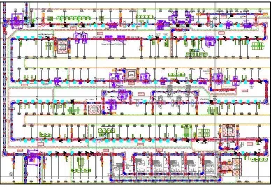
B Multiple Loops Layout: An engine assembly is divided into multiple
loops, usually three or four. A first short block loop consists of engines without
cylinder heads and timing component. A second long block loop may encompass
two loops for an engine before dressing. A later or final dress loop installs wire
harness and vacuum hoses. Figure 1.2 illustrates an example of multiple loop
2
Figure 1.1: Single Loop Engine Assembly Line (from J.A. Krause Machinenfabrik GmbH)
3 1.3 Engine Assembly Station Types
There are two types of engine assembly stations: 1- Manual and 2- Automatic.
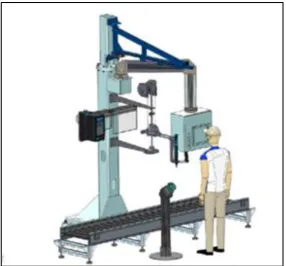
A Manual Assembly Stations: Today’s engine assembly lines involve 150 to 180
workers performing manual tasks using specific tools for each station (powered
equipment like rundown tools, or manual ones to handle parts for assembly). This
type of station is the most flexible, as operators adapt easily to any situation. A
human has better dexterity than any machine or robot; he or she also learns and gains
experience by helping detect potential anomalies and developing solutions. An
example of a manual station is shown on Figure 1.3.
Figure 1.3: Typical Manual Work Station used in assembly line
Each manual station is built as a module, fitted with a Human Machine Interface
(HMI) controlled by a Programmable Logic Controller (PLC), while hosting tooling
4
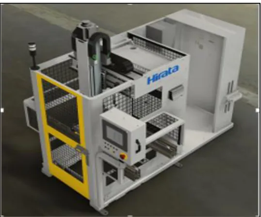
B Automatic Assembly Stations: These stations include fully automatic machines
which complete tasks without operator intervention, and semi-automatic stations
where machines perform portions of an assembly leaving the remainder for operators
to complete by unloading or loading the assembly in progress to other machines for
performing complementary tasks. Automation is usually assigned to repetitive and
tedious tasks which are difficult on operators. Engine assembly lines include many
types of automatic stations such as:
Robotic Cells: Typically consisting of an industrial six-axis robot
performing tasks, for instance a material handling function such as
pick and place;
Conveyors: Properly fitted with stops and controlled by PLC to
move pallets from station to station;
Buffers: Usually used to store pallets in process;
Elevators: Properly placed to transfer pallets over lines between
loops;
Bolt and Dowel Feeders: Automatically embedded to sort bolts or dowels and feed them to machines for install and rundown;
Poke Yoke: Relied upon to assure Quality Control (QC) functions,
in terms of simple probing or vision system detecting assembly
errors;
Test Stations: Introduced at certain stages of an assembly to check
functionality throughout production, for leaks, compression,
running torque, or complete engine also called Cold Test using an
electrical drive to test the produced engine at certain speeds;
Rundown Stations: Automatically inserted to run down bolts for
instance, to specification;
Press: Crafted to consistently press dowels into an engine block or
cylinder head following a specified depth and/or force;
Room Temperature Vulcanizing (RTV) Applications: Engineered
5
Vision systems are used to guide presence and location of RTV -
An example of an automatic station is shown on Figure 1.4.
Figure 1.4:Automatic Assembly Cell (Hirata Assembly Systems,
http://www.hirata.co.jp/en/)
Automatic stations are more complex than manual stations; they are also built as
modules with each machine hosting PLC and HMI.
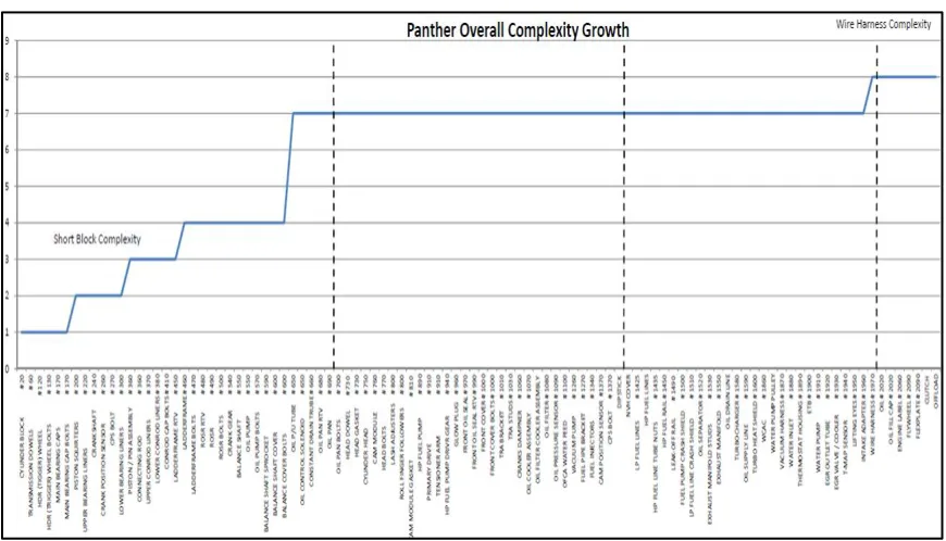
1.4 Engine Variants
A typical engine assembly line is designed to run many variants, usually 2+1; where +1
refers to a future engine within the same family yet to be designed. An example of an
existing line is illustrated on Figure 1.5. Note that beginning with one engine block could
result in multiple engine derivatives. The first stations on the short block handle one part
type while stations in the first and final handle all engine derivatives. Derivatives
multiply by adding more engine blocks to the production line, and could reach 15 to 20 at
any point in the life cycle of the manufacturing system. Consequently the +1 variant
forces the engine assembly designers to implement the RMS paradigm to facilitate
6
Figure 1.5: Engine Variants through a Typical Engine Assembly Line
1.5 Enablers for Reconfigurability in Engine Assembly Lines
Many characteristics of Reconfigurable Manufacturing Systems (RMS) are implemented
in the design of new assembly lines in order to manage perceived complexities resulting
from variants and future products. A new engine line needs hardware and software
enablers to produce required variants. Hard enablers typically used in engine assembly
lines are listed below:
a) Nested Pallet: Designers use adaptor plates with two faces to handle
potentially completely different engine blocks when running multiple
engine blocks on a same pallet: Each face is designed with proper locators
for a given block, to rotate when another block type is produced;
b) Modular Station: Modularity is an RMS characteristic allowing relocation
of stations if required, while duplicating stations and installing them in
parallel for volume increases;
7
c) Space Protect: Spaces are left for future stations handling +1 variety with
conveyors to insert strategically throughout a line in order to
accommodate additional stations.
d) Manual Stations: Operator stations are most flexible: Humans handle any
assembly with proper tooling.
e) Industrial Robots: Fitting a six DOF robot in an assembly cell with a
changeable end effector provides necessary flexibility to handle multiple
variants.
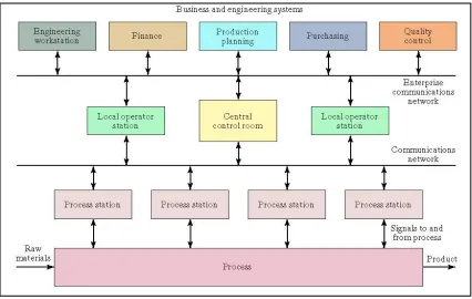
Today’s trends in controls software evolve towards modularity to accomplish desired
architectures. Figure 1.6 shows an example of Enterprise PC distributed Control System.
Figure 1.6: Enterprise PC Distributed Control System (MGroover, 2000)
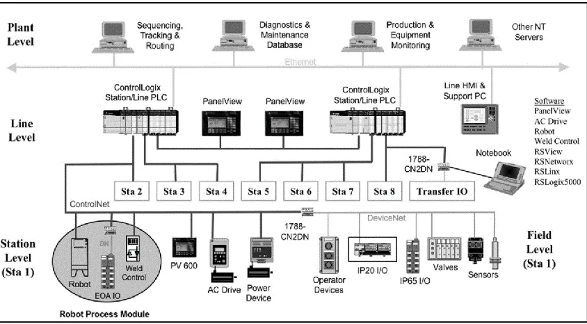
A controls system of an engine assembly line is complex and composed of hardware
elements connected through a communication bus. Figure 1.7 depicts typical hardware
for a distributed control system. Such hardware multiplies by at least a hundred for a
8
Figure 1.7: Distributed Control System Hardware (http://ab.rockwellautomation.com)
1.6 Motivation for Research
In current automotive assembly circles, control software is usually customized to each
machine; similar machines could have different pieces of control logic. Programmers
usually use experience from previous projects. They consider similar machines coded in
the past then modify the associated coding to suit the new machinery. The result is
always a tailored program that is rigid, station specific, and inflexible to change in case of
machine hardware modification. This approach triggers high costs and decreases
innovation. Control systems need to adopt the latest developments in IT for increased
effectiveness while responding quickly to reconfigurability requirements. Modularity is
an essential ingredient in controls software to translate from station to station.
According to Chan et al. (2000), Object-oriented Programming (OOP) is the dominantly
used software technology in the design of manufacturing controls; Mehrabi et al. (2002)
believes that OOP is also the choice for RMS controls. Agent-based technologies are very
effective in dealing with unexpected events. Agents could be added or replaced with ease,
leaving the built system flexible and adaptive (Ferber, 1999) (Kendall, 2000).
Agent-based systems are not an exception to the rule. In spite of many desirable features, they
9
system performance. A potential problem for large systems is deterioration of
performance from excessive required communications between agents. Component-based
software technology became widely popular because of ease of development and
integration. Component-based software architecture provides reconfigurable software
coding for RMS controls, and is able to adapt to physical changes in manufacturing.
1.7 Objectives and Problem Statement
It is imperative to seek designs of reconfigurable controls to build true RMS lines
producing families of products with many variants of engines. The possibility of reusing
the same coding with minimal interventions makes this as important as the development
of the manufacturing system hardware. The literature is unfortunately limited in applying
reconfigurable control to automotive manufacturing. Very few publications are found on
engine assembly manufacturing, because of the proprietary nature of such undertakings
by each manufacturer.
This research aims at studying and developing a modular control architecture using newly
emerged information technologies - such as component-based software technology and
IEC 61311-3 Standard - towards building function blocks for controls. The proposed
software architecture offers all RMS characteristics of modularity, flexibility, and
robustness. Features used in coding the control methodologies used in this thesis include:
• Reconfigurability: Coding suited for RMS designed hardware, which considers modularity and ease of adaption to new manufacturing scenarios.;
• Reusability: Software collecting a library of components to reuse across entire assembly lines;
• Robustness: Programming which maintains system operability to counter malfunctions;
• Immunity to Disturbances: Controls handling machine malfunctions/errors yet retaining production, and
• Plug and Play: Software components (function blocks) which are easy to assemble, to build control systems for Reconfigurable ManufacturingS systems.
10 CHAPTER 2
Literature Survey
Controls’ architecture design should mimic the hardware design of a system. Evolutions
in manufacturing paradigms and innovations of the microprocessor and Information
Technology (IT) further transformed controls in manufacturing. The latter introduced
hardware, software solutions and advanced algorithms for machines and systems while
the former dictated controls’ architecture. This chapter presents literature related to
controls architecture and software.
2.1 Traditional Control Architectures
(Diltis et al. (1991) traced the evolution of controls’ structures for Automated
Manufacturing Systems (AMS). Three main controls’ architectures were presented: 1-
Centralized, 2- Hierarchical, and 3- Heterarchical. The authors also reviewed
characteristics, advantages, and drawbacks of each of the topologies.
2.1.1 Centralized Architecture
This appears to be widely used in continuous process controls, to concentrate planed and
processed information in a single decision node. The architecture requires powerful
processing to handle large amounts of recourses. Advantages include simplicity of central
startup, shutdown, and program archiving. Coding is extensive and difficult to develop
and maintain, making codes unsuitable for Reconfigurable Manufacturing Systems
(RMS). Figure 2.1 presents an example of centralized architecture.
Figure 2.1: Centralized Architecture System Sample Control
ler
11 2.1.2 Hierarchical Architecture
The International Standard Organization (ISO) and National Bureau of Standards (NBS)
establish hierarchical controls models (Bauer et al., 1994). Both are similar from top to
bottom, but differ in the number of stages. The former breaks the organization into six
levels: 1- Enterprise, 2- Plant, 3- Area, 4- Cell, 5- Station, and 6- Equipment, while the
latter into five levels: 1- Facility, 2- Shop, 3- Cell, 4- Station, and 5- Equipment. This
architecture is recognized for its efficiency and robustness, due to an easy structure.
Figure 2.2 demonstrates an example of hierarchical architecture.
Figure 2.2: Hierarchical Controls System Sample (http://ab.rockwellautomation.com)
2.1.3 Heterarchical Architecture
Heterarchical architecture consists of a distributed control system, grouped independently
but cooperating as “agents”. Tasks are performed by exchanging information among agents. Duffie and Prabhu (1996) presented major works and design principals relating to heterarchical controls to promote extensibility, self-configuration, and adaptation, to real-time events such as in equipment failures. Figure2.3 shows an example of heterarchical
12
Figure 2.3: Heterarchical Controls System Sample
2.2 Holonic Manufacturing Systems (HMS)
Koestler developed the Holon concept, inspired by social organizations and living
organisms. He was inspired by the hybrid form of modules or components in actual these
systems. Koestler (1969) defined Holons as self-contained wholes of subordinated parts,
related inversely. The HMS consortium arranged Koestler’s proposal into a series of
concepts for manufacturing systems. The objective was to enable production outcomes
according to Holonic organisms and societies in life that have similar characteristics in
terms of stability in adversity, and adaptability and flexibility to fluctuations (Van
Brussel et al., 1998). Valckenaers et al. (1994) define HMS as:
Holon: An autonomous and cooperative block for manufacturing, such as in
transformation, transportation, storage, data validation, and actual objects like
date and processing components - A Holon can be part of another Holon as well.
Holarchy: A series of Holons readily cooperating for a target or purpose, setting fundamental rules to associate Holons and establishing freedoms.
Farid (2004) surveyed HMS literature related to architectures, methodologies, protocols,
algorithms, and interactions. He also highlighted open research challenges and
roadblocks to industrial adoption. Babiceanu et al. (2006) reviewed the public domain as
well, and included development and applications of Holonic systems.
Control ler Control ler Control ler
13
The HMS concept combines best features of hierarchical and heterarchical organizations
(Diltis et al., 1991), in academic circles. However applications in industry are scarce,
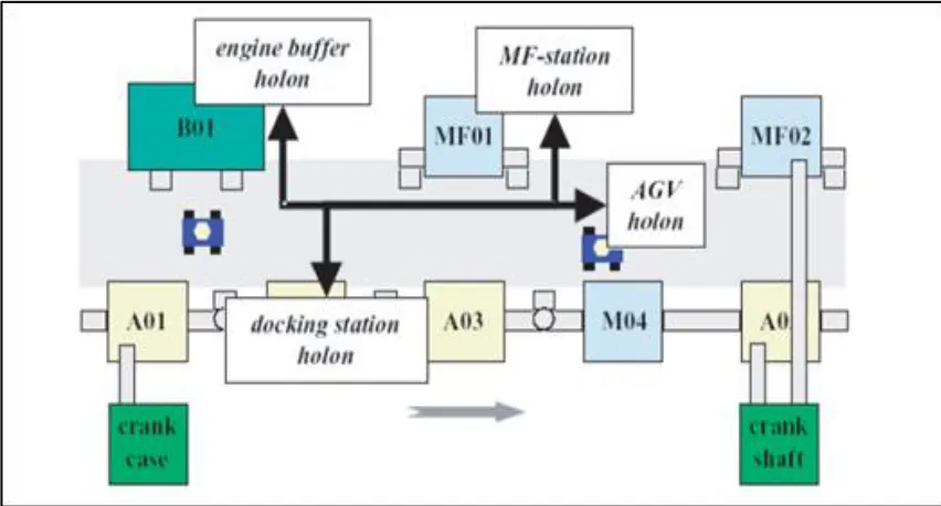
with a single study by Bussmann and Sieverding (2001). The latter applied the Holonic
paradigm for Mercedes-Benz V6 and V8 engines. The study consists of: 1- Introduction
of flexible buffers to decouple production line, 2- Addition of concurrent multi-functional
stations for machine backup to overcome potential breakdown or production scalability,
and 3- Development of Holonic controls for assembly, as in a Holon per Docking Station
(DS Holon), per Manufacturing station (MF Holon), per Engine Block buffer (EB
Holon), and Automatic-guided Vehicle (AGV Holon). Figure 2.4 shows the resulting
layout. The new assembly profile and control system contrasted an existing assembly
system based on simulation and plant data. Results showed the new layout to deliver a more robust and scalable system.
14 2.3 RMS Controls System State-of-the-art
Mehrabi et al. (2000) presented two main characteristics for RMS withmost influence on
systems’ software architecture:
a- Modularity: To guide design components of all systems, codes, and supporting
platforms, as modular, and
b- Integrability: To design with readiness for new technology introduction into
components and systems.
Software design modularity and integrability co-exist. The former enables scalability and
simplicity in software design. The latter facilitates plug-and-play concepts.
Open-architecture controllers proved essential for reconfiguration in manufacturing (Proctor, 1998) (Koren, 1999).
2.3.1 Open Control Architecture Systems
The IEEE Guide POSIX Open System Environment (OSE) defines “an open system” in section 2.2.2.28 as one that imbeds general specifications and standards related to interfaces, as well as services and supporting formats, to rightfully create application software in terms of:
Portability with minimal changes across supplier systems;
Interoperability with applications to in-house and third-party systems as well, and
Interaction with operators facilitating portability.
Pritschow et al. (2001) indicate that software fulfilling IEEE’s requirement should
satisfy: 1- Vendor neutrality, 2- Consensus drivability (interest group), 3- Standards-basis (National/international), and 4- Free availability.
Since 1990, several research projects (OSACA/HUMNOS, OMAC, OSEC, OCEAN, ORCOS, JOP) have targeted Open Architecture Control or OAC for machines (Brecher et
al., 2010) (Pritschow et al., 2001) (Katz et al., 2000) (West, 2003). The Unified
15
for Real-Time Systems (DARTS) and Real-Time Specification Methodology (RTSM) to propose UROCA. One relevant project, the Open Modular Architecture Controls at GM Powertrain (OMAC), was adopted by all major automakers. Publication Motors (1996) describes OMAC’s concept architecture and standard Application Programming Interface (IPA) as externally linked to various OMAC building blocks. A generic PC running Windows operating system is recommended for hardware platform; Profibus DP and Interbus are selected for networking and specify flowchart/IEC 61131-3 compatible languages for programming.
2.4 Control Software Development for RMS
Design and implementation research for RMS control software is common in literature. All modelling methodologies and programing languages are implemented as controls to reduce the gap with IT.
2.4.1 Object Oriented Programming (OOP): OPP is a software technology
established to design production controls, and is popular in academia (Grabot and Huguet, 1996) (Howard et al., 1998). Ka et al. (1998) highlighted a simulation
framework based on objects to develop and evaluate multi-agent manufacturing
architectures. Chan et al. (2000) established a similar architecture to design and
implement reconfigurable controls. Holons, in Holonic manufacturing systems, are often programmed as objects using OOP.
2.4.2 Unified Modeling Language (UML): UML is an open smulation
language used to create abstract models for systems. Advantages of UML diagrams include simplicity and standardization. Huang et al. (2001) designed modular real-time control system architectures based on UML. Panjaitan and Frey (2007) combined UML and IEC 61499 in a distributed control system.
2.4.3 Petrinets (PNs): A PN is a modeling script in distributed control system
16
allowed Petrinets in PC software to control systems. Lee and Hsu (2000) designed logics with Petrinets, as Ladder diagrams for industrial PLCs
2.4.5 Agent-based methodology: Some developers consider agents as objects;
others differentiate between agents and objects even if commonalities are shared. Both approaches however envision using objects and agents together in developing software systems (Odel, 2002). Cândido et al. (2007) described a multi-agent implementation to manufacturing floor controls, with plug-and-play and system reconfiguration. Shop floor components were identified for improved adaptability and interaction to environmental requests. Monostori et al. (2006) introduced agents and multi-agent systems in coding for manufacturing applications. Their comprehensive survey emphasised methodological issues and agent deployment in industrial systems. Agent technologies and manufacturing evolutions were to proceed together. Vrba et al. (2011) presented methodologies to design agent-based control systems, related tools supporting implementation and validation, and agent applications for industrial systems. Metzger and Polakow (2011) surveyed technical applications in automating continuous industrial processes. Analysis of the literature followed main trends in research, such as based supervisory controls shifting interests to low-level agent-based control algorithms.
2.5 Component-based Software Technology (CBS)
17
reviewed software engineering in industrial automation, standards and norms, as well as models and methods and strategies to develop industrial software. The survey was geared to academia not industry. Mahmood et al. (2007) presented an extensive literature survey
where many facets of CBD were presented in the software development field, including
risks, benefits, selection and identification methodologies, in addition to means and tools
of development. The survey concluded that CBD still requires support and research to
achieve a full potential and economically viability.
2.6 Industrial Control in Automotive Sector: State-of-the-art
Clearly, PLCs are widespread in the Automotive Industry. They were introduced when General Motors (GM) looked for a robust replacement of the relay logic. A first commercial PLC by Bedford Associates was the Modular Digital Controller (MODICON) (Segovia and Theorin, 2012). Both PLC hardware and programing have since evolved throughout the manufacturing industry. Initially PLCs were programmed using Ladder logic, consisting of a structure similar to the relay logic which simulated electrical wiring control circuits. Today, PLC programing follows the IEC 61131-3 Standard and five programming languages (Karl-Heinz and Tiegelkamp, 2010):
1. The Ladder Diagram (LD): A graphical language widespread in automotive
plants throughout North America due to\ simplicity of use by maintenance staff for troubleshooting and adjustments;
2. The Function Block Diagram (FBD): A graphical language used to
encapsulate pieces of logic for reuse where the logic itself can be written in Ladder or other languages;
3. Structured Text (ST): An advanced programming method resembling Pascal in
PCs, used for implementing complex algorithms to control uncommon machinery;
4. Instruction List (IL): A language similar to machine language when
programing microprocessors, that uses registers and basic logic instruction, and
5. Sequential Function Chart (SFC): More of a sequencing tool than a
18
Programmers use more than one of the IEC 61133-3 languages to write a PLC program for a complex machine. Ljungkrantz et al. (2010) studied controls coding for PLC programming in two Swedish automotive companies, Volvo and Saab. They reported that: 1- PLC programs are mainly written in Ladder diagrams and SCF, frequently as reused function blocks, and 2- Although function blocks were adopted, their behaviors were lightly detailed. Di Giovanni et al. (2013) described a methodology for automatic generation of Ladder Logic Diagrams (LLDs). The five-step method relies on a unique model generated from the entire manufacturing process specifications. Lee et al. (2006) overviewed frameworks for automatic generation of PLC codes. The project was not implemented, in spite of cooperation with Ford Motor Company, mainly because of a need for manual intervention to adapt and integrate coding with existing programs.
Ryssel et al. (2009) proposed a methodology that generates function blocks based on web
technologies. The approach faced hurdles for adoption in the Automotive Industry, the
major being a need for high programing skills - not readily the case among maintenance
personnel in production plants. Breslin et al. (2010) introduced another methodology that
promotes the use of Semantic Web Computing (SWC), and aside from similar shortfalls
encountered by Ryssel et al., the authors agree that the methodology needs to mature
before any further expansion. Ljungkrantz et al. (2010) proposed a framework called
Reusable Automation Components (RAC). The methodology offers verification tools for
programing, applied only to basic examples so more development is required to satisfy
industry requisites. Hirsch (2010) proposed the use of SysML technology which was
implemented using IEC61499 Standard on a modular manufacturing cell, but such
technology remains challenging for plant personnel to support and use. Many of the
presented concepts induce a paradigm shift in software controls’ development methods
rooted in the industry thus the resistance to adoption.
2.7 Summary
19
20 CHAPTER 3
System Engineering Approach to Control Software Design
The primary objective of this research is to design a reconfigurable software control
system for an engine assembly line. Because of the design complexity of such a
manufacturing system, requiring teams of engineers to work concurrently to create a
reliable production line following multi-phase processing, an effective and systematic
methodology remains greatly needed.
3.1 System Engineering to Design Controls Software
Over the past few decades new paradigms were introduced, like Flexible manufacturing,
Changeable manufacturing, Reconfigurable manufacturing, in response to manufacturing
systems and controls system’s continuous increases in complexities. Limitations in
programming languages readily understood by shop floor personnel when creating
control systems in the manufacturing industry remain current. Academia is more
advanced regarding controls modeling and coding methodologies, but they are yet to
demonstrate efficiency when implemented on bigger scales in industrial settings.
Controls must be included as an integral part of systems engineering design.
Traditionally complex software used systems engineering for design, testing, and
implementation. Many systems engineering methodologies and approaches are widely
used in software engineering literature, such as the Vee model, Waterfall or Linear
model, the Spiral or Incremental model (Kossiakoff, 2011). Each approach has
applications, benefits, and limitations. The Vee model was chosen in this research, due to
simplicity of use and most importantly testing before coding which saves time as defects
are identified at early stages. In addition, system and user requirements are clear and do
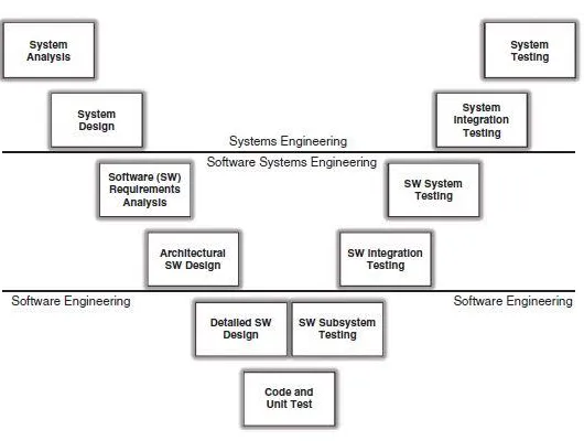
not change during the life cycle of a project (Sage and Cuppan, 2001). Figure 3.1
presents the traditional Vee model as per the Institute of Electrical and Electronics
Engineers (IEEE) for software engineering. Some steps shown on the graph do not apply
to developing the model in this thesis, because of specificity of controls logic software.
The Vee model consists of two main steps: 1) A top to bottom design, starting with the
definition of software requirements and design parameters, then 2) A bottom-up design,
21
Figure 3.1: IEEE Vee Model for Software Systems Engineering Process (Kossiakoff, 2011)
3.2 Design Steps for Engine Assembly
With product design reaching a specific millstone, manufacturing teams get involved in
reviewing product design for manufacturability (DFM) prior to beginning the design of
manufacturing system. Subsequently, many teams join efforts and work concurrently to
design an engine assembly line. The main steps of such an undertaking are:
3.2.1 Design of Assembly Process
Assembly sequence and precedence graph are first defined (Henrioud et al., 2003).
Product differentiation is always delayed in processing, for a family of engines
(AlGeddawy and ElMraraghy, 2010) Tasks are identified and assigned to multiple
stations, requiring manual operators, or semi-automatic to fully automatic operations,
depending on the complexity of operations, ergonomics, and safety factors. Process
designers tend to allocate repetitive and most demanding operations to automatic stations,
to prevent operators’ injuries. Quality assurance test stations are also identified and
strategically located throughout an assembly process. Every engine manufacturer uses its
specific internal processes; for example Ford Motor Company uses Ford’s Production System (FPS), and Toyota uses Toyota’s Production System (TPS) - both encompass all
production philosophy and influence the design of assembly process, and assembly line
22
3.2.2 Design of Mechanical Machinery and Tooling
Machine designers start conceptualizing an associated assembly system upon completing
the process design. They begin with an assembly line layout, conveyor system, and
pallets to use in producing an engine. A conveyor system includes “pallet rotates” and “pallet transfers”. Some engine assembly systems are equipped with Automatic Guided
Vehicles (AGVs) for part deliveries and pallet transportations to add parts routing
flexibility to the line. Mechanical designers use the same base design and footprint for all
manual stations and tooling. Automatic stations are more complex to design and
depending on the operation a designer has few options. Robotic cells using industrial
robot arms are most common stations for flexibility, but dedicated machines offer
specialized tasks such as dowel or cup plug presses, more repeatable and reliable when
built on rigid structures. Part and pallet transfers for long distances require the use of
gantries. Test stations are semi-automatic with operator interventions to connect an
engine to test probes using electrical wires or air hoses, but at times they can be fully
automatic. Buffers and Automatic Storage and Retrieval Systems (ASRS) are also part of
an engine assembly system. Finally, mechanical parts, like tools, are designed by tooling
engineers for the engine assembly line. These range from a simple hand tool an operator
uses for a determined task, to a complex end effector of a robot arm.
3.2.3 Design of Controls Hardware System
Controls engineering teams work with machine designers to comprehend intended
functionality and determine sensors for controls system, such as limit switches, speed
sensors, proximity switches, temperature sensors, etc. Other items to design include
actuators, like valves for pneumatic cylinders, servo motors, contactors, and relays. Such
electrical components are controlled by PLCs. The mechanical assembly system dictates
a controls’ architecture. A distributed controls system best fits a RMS system. All stations have the same functionality of processing a part from a controls system’s
perspective where each station is fitted with a Process Logic Controller (PLC) that
orchestrates physical devises (actuators) and is responsible for the station’s functionality.
A communication routine is also chosen for networking the PLCs. Each PLC
manufacturer has proprietary protocols. Profinet is a main protocol dominantly used for
23
an engine from station to station. Each pallet has a tag storing all production data for the
engine carried over, and each station is also equipped with a reader/writer to scan tag
data, determine required tasks, and update tags with status of operations (failed or
successful). Tags hold serial numbers identifying engines as well.
3.2.4 Design of Controls Software System
Controls run from PLCs that scan all field sensors (inputs) for statuses, and execute logic
program, and updates outputs to actuate all field actuators. All station PLCs are
networked in an engine assembly system. Figure 3.2 highlights a grouping of PLCs
communicating through Ethernet switches to exchange production data.
Figure 3.2: Network of PLCs in Engine Assembly
Designing controls begins with thorough reviews to understand process and functionality
of each station. A station’s functionality is decomposed into basic steps to follow while
executing related tasks. The PLC logic mainly sequences steps to control statuses of
machines, set before the commencement of coding (control logic writing). Programing
language, machine interface, and machine interlock signals are chosen, and then a
program structure is set prior to coding. Presently more than 90% of logic programmers
24
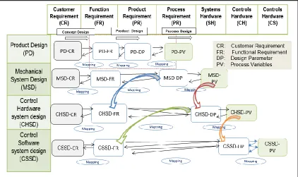
The process of engine assembly design is multi-phase. Figure 3.3 illustrates the
Axiomatic Design (AD) model encompassing the four steps presented. It is worth
mentioning that such steps are not completely sequential, as teams work simultaneously,
yet interface constantly to accommodate changes and alleviate roadblocks potentially
facing project’s life cycle.
Figure 3.3: Design Framework Extended from Yien and Tsang (1996)
The last step of controls software system design is of primary importance in this thesis.
Control Software System Design (CSSD-FR) denotes functionality of software modules
and originates from Control Hardware System Design (CHSD-DP) or controls hardware
modules in Figure 4.3. Any CSSD-DP reflects on the structure of controls system, the
interaction of Input/output (I/O) and their statuses with program running. Process
Variables PVs for CHSD-PV enable software design parameters and constrain CSSD-DP,
25 3.3 Controls Software Design Process
This research focuses on the design of controls, using systems engineering and Axiomatic
Design. The systematic design process is decomposed into a set of sequential activities:
1. Define user requirements for controls system;
2. Identify a controls hardware system;
3. Design a controls software system according to users’ requirements (this is the
most important step, to decompose in tasks);
4. Code and test Function blocks
5. Combine Function Blocks to form a machine program and test protocol;
6. Deploy machine programs and test the assembly line, and
7. Integrate and validate the system for the production line.
It is possible to shift back and forth between steps while designing a system, especially
when testing fails. Experience confirms that changes to well-structured software are
effortless, a matter of altering a few lines of code. Unfortunately experience also
confirms the contrary, with unpredictable outcomes. A simple software change usually
requires a complete retest of system (Blanchard et al., 1990). Figure 3.4 shows design
phases that form the present research’s methodology.
26 3.3.1 Software Requirements Definition
At this stage, customer requirements are documented, in terms of enumerating system’s
roles. The RMS controls system sought in this research must not only integrate the
software, but the hardware system as well. By analogy to characteristics defined for an
RMS system by Merhabi et al. (2000), five traits are proposed in reconfigurable control
systems to enable integration to physical RMS. Such properties are to embed in the
designed controls system for system re-configurability:
a) Modularity: System components should be modular and easy to build upon in a
larger coherent system. The main enabler is the standard interface for control
components. Modularity is achieved for controls software, using subroutines,
databases, and Function Blocks that interface with one another.
b) Integrability: Integrating modules and components rapidly, with abilities for
new technology assimilation, is quite important. Therefore a controls system
should be designed with an open architecture.
c) Diagnosibility: The potential to identify anomalies quickly for corrections and
resuming operations is crucial. Controls software should have fault messaging
displays on Human Machine Interfaces (HMIs) besides faults’ storage on servers
for historical tracing.
d) Convertibility: Transforming functionality of existing systems to allow for
quick product changes is key. A controls system should thus track each model to
produce, by identifying each product with a Radio Frequency Identification
(RFID) tag or a barcode to scan.
e) Customization: The ability to respond to changing production capacity and
flexibility within a product family falls under customization. A controls system
should orchestrate speeds of different motions within machines and transport
systems such as conveyors to cope with volume demand and product variants.
27
Table 3.1: Hardware and Software Characteristic Requirements for RMS System
RMS Characteristic
Customer requirements
(CR)
Hardware characteristic Control software characteristic
Modularity -Modular machines
-Modular system
-Use of subroutines
-Use of function blocks
Integrability -Using ISO components same foot
print, can be interchangeable
-Open architecture
Diagnosability -Use sensors for feedback on all
actuators
-HMI to display faults
-Server to store faults
Convertibility -Flexible tooling,
-Changeable end effectors
-Flexible layout
-Use RFID technology for tools and
end effector identification
Customization -Ability to scale production volume
-Ability to run a family of product
variants
-Use variable speed control on
transport system
-Use servo slides for motions
-Use RFID technology to identify
variants
3.3.2 Controls Hardware Identification
By analogy to human anatomy, controls hardware represents the nervous system. A
controls hardware system is usually dictated by mechanical design. Configurability,
entailing modularity of design for system and individual machines, as a main
characteristic, is to build from the ground up. Using reconfigurable machines definitely
helps establish a reconfigurable system. Selected field sensors and actuators must assure
good functionality of equipment and safe use of machinery. Safety of operators is crucial
in manufacturing and controls industry, and is incorporated in many Government
regulations such as OSHA in North America or the Machine Directive and ISO Standards
in Europe. Safety requirements are well documented and guidelines should be followed
28
machines such as “machine is ready for part”, “machine cycle done”, etc., are defined and
standardized. All engine assembly lines use RFID to track product evolution during
production; stations are equipped with readers and pallets with tags. Figure 4.5 shows a
typical machine with PLC, sensors, and interfaces.
Figure 3.5: PLC Rack Connected to Field Sensors and IT
3.3.3 Control Software Design
An objective in controls development is the ease of rewriting or modifying software each
time a Reconfigurable Manufacturing System changes, thus the need for a reconfigurable
controls program. Major automotive manufacturers plan to run multiple engine
architectures on engine production lines for two reasons: 1) To optimize the enormous
investment required to build a new engine line, and 2) To cope with the short life cycle of
internal combustion engines according to the increasingly stringent regulations for fuel
consumption. An engine life cycle has over last decade been shortened from 10 years on
average to only three years. Automotive manufacturers consequently retool lines every
two to three years. It is challenging to retool a manufacturing facility such as an engine
assembly line in full production, hence, the search for control system flexibility and
29
the capability to build two current products architectures and still able to run a future
model. This is possible by embedding reconfiguration principles in both system software
and hardware. A literature survey within this research field indicates attempts to develop
required logics for RMS using different methodologies and languages. Nevertheless,
none could successfully replace the mature PLC Ladder logic which electricians master.
The methodology chosen for this research is inspired by component-based software
technology, meeting requirements for re-configurability, while being based on Ladder
logic for programming.
3.3.4 PLC Functions in Production Machine
PLCs dominate controls and automation as the brains to a production machine, since their
invention. They have evolved from basic functions as replacements to the relay logic, to
more sophisticated devices, with multiples functions, due to technological advances in IT
and electronics and the constant demand for additional functionality. The major tasks
that a PLC supports are:
a- Operation sequencing: Hardware design of PLCs and physical I/O cards allow
for signal collections from controlled systems and generation of output signals
applying to the system. Inputs are usually discrete signals from different
components of machinery occurring in responding to PLC outputs or external
factors. PLC programs produce desired outputs in right sequence for machines
control.
b- Safety devices monitoring: Every production machine has devices ensuring
safety of operators and preventing damage to components in case of unforeseen
events or malfunctions. Emergency stops, light curtains, safety mats, etc. are
constantly monitored.
c- Error handling: A PLC program should detect any malfunction in a machine
component, and act according to a programmed response to the fault. The
response could be an error message, a controlled shutdown of machine, or other
30
d- HMI messages: The most automated cells in production still require human
intervention to reset a fault from malfunction or simply run a manual cycle for
maintenance: HMI are used to enable such human-machine interactions. They
display cell statuses and faults and other data of interest to production or
maintenance personnel. The function of a PLC is to generate these messages and
send them to the HMI; a PLC also takes inputs from HMI and processes them.
e- Part tracking: PLCs are gaining similar computing power and memory to those
of PCs, due to advances in technology. Tasks are also becoming more complex as
programmers are constantly requested to add new features to satisfy machine
users. Part tracking is an example of task a PLC controls.
f- Data transfer via Ethernet to a corporate network for reports: PLCs are
integral in the corporate network. They are monitored and programmed remotely
from anywhere, with programs uploaded for archiving and data exchange for
production supervision or otherwise, as deemed necessary.
Each of the above functions is programmed in PLCs, based on many function blocks for
each associated task.
3.4 Component-based Software Technology
Component-based software is a mature concept in software engineering, as it aims at
reusing proven coding to ensure savings and guaranty reliability. Databases of built
software components render new program developments a matter of assembling standard
components (Szyperski, 1998). Software components emerge as communication network
boxes linked with connecting wires, similar to physically interconnected hardware
components (Cox and Song, 2001).
3.4.1 Software Components Definition
A software component is an independent entity that executes a predefined task. It is a
standard software element fitting a model with the ability of independent deployment
without modifications (Councill, 1998). A software component is a unit with specified
31 3.4.2 Software Component Characteristics
Coding for Software components should be:
Standard, yet conform to class specifications like interface, meta-data,
programming language, documentation, and means of deployment;
Independent, for launch and composition without needing other specific
components - Components need external services, at instances, in which case they
should be declared and grouped separately;
Composable, interacting with environments with predefined interfaces, yet allowing external components to access information and attributes;
Deployable, to function alone as self-contained entities, and
Documented, for users: Documentation should encompass interface and complete
programming details including syntax and semantics.
Logic function blocks if used correctly, as described in IEC 61131-3, have all of the
above characteristics, and could be geared at developing a component-based controls
system.
3.5 Summary
In this chapter, benefits of using systems engineering in the design of controls systems
for hardware and software are discussed. The Vee model was chosen in this thesis due to
its simplicity. Component-based software was also introduced with advantages
32 CHAPTER 4
Control Software Development Methodology
A methodology to design and develop controls software is presented in this chapter. A
case study “Manual work station”; is detailed, all steps are demonstrated sequentially.
4. Component-based Approach to Machine Controls Software
Distributed architecture accommodates best this proposed research: Each machine is
controlled separately, to run in a standalone mode, and can also be considered as a
module in building an engine assembly line. Machines are mechanically built as modular
as possible, for
Figure 4.1: Modular Design for Manual Workstation
reconfigurability. Controls logic should be modular for each mechanical module. The
granularity of a controls system depends on that of the mechanical design. Granularity
means to what extent to decompose a mechatronic system. Granularity of reconfigurable
controls software must be equal or lower than that of the mechanical design. A
cladogram methodology is used herein to decompose controls software into required
granularity. Figure 4.1 presents a modular design for a manual work station equipped
with all controls hardware. A pragmatic approach should create a system with least
33
modules required within a given system and still remaining able to build any desired
machine configuration (Harrison et al., 2007). In practice, special attention should be
made to the desired functionality for reuse, while maintaining modularity.
Mechanically, a manual station as that on Figure 4.6 decomposes into:
1. A conveyor body;
2. A pallet stop, and
3. An electric motor.
Controls wise the station can be decomposed into:
1. A PLC station controller (Controller/Brains);
2. An electrical motor control (Output 1);
3. A pallet stop control (Output 2);
4. A HMI for operator interface (Output3/Input 4);
5. A RFID antenna for pallet identification (Output4/Input 5);
6. A proximity switch to detect presence (Input 1);
7. A proximity switch to detect any stop raised state (Input 2);
8. A proximity switch to detect stop lowered state (Input 3);
9. Feedback to indicate motor running (Input4);
10.A feedback for motor faulted (Input5), and
11.A feedback for stop faulted (Input 6).
4.1 Decomposition of Controls System
Distributed controls architecture for hardware system is chosen for this research, to allow
creation of modular controls system satisfying RMS needs. Moreover, PLC
programming should follow components-based software technology as a prerequisite to
satisfy RMS principals, hence, the need to decompose the controls system into optimum
granularity. It is possible to create more complex products varieties by defining a finite
number of basic production tasks. A production system can be seen as a set of controls
components with devices in control of basic tasks, then combining the basic mechatronic
components can result in complex assemblies. Basic mechatronic components can be
34
reconfiguring simple components (Harrison et al., 2007). A cladogram could be used to
granulize controls and decompose it into basic components.
4.1.1 Decomposition of Controls System using Cladistics
Many methodologies are used in the literature to decompose systems. Systematically,
DSM is frequently used in systems engineering for modularization. Systems are dealt
with easily if decomposed into basic elements. Such approach is very effective for
analysis, representation, and modeling (Browning, 2001). An original method was used
by AlGeddawy and ElMaraghy (2013) for system decomposition and optimum
granularity for modular product design. The methodology lends itself very well to the
current research seeking the best granularity of built blocks (Logic Function Block) for
designing complex systems. The manual station of Figure 4.1 is used as a case study to
explain the Methodology which is divided in multiple sequential steps:
A STEP 1 – Identification of Control System Components
Table 4.2 contains all controls hardware components of a manual assembly system.
Associated numbers or letters are used to ease the manipulations. The table shows the
modules for the manual work station in Figure 4.1.
Table 4.1: BOM for Manual Work Station
Number Component Name Symbol
1 An electrical motor control A
2 A pallet stop control B
3 A HMI for operator interface C
4 An RFID antenna for pallet identification D
5 Proximity switches to detect pallet presence E1,E2 & E3
6 A proximity switch to detect stop raised state F1 and F2
7 A proximity switch to detect stop lowered state G
8 A Feedback to indicate motor running H
9 A feedback for electrical motor faulted I