Securing Circuits Against Constant-Rate Tampering
Dana Dachman-Soled and Yael Tauman Kalai
Microsoft Research New England
Abstract. We present a compiler that converts any circuit into one that remains secure even if aconstant fraction of its wires are tampered with. Following the seminal work of Ishaiet al.(Eurocrypt 2006), we consider adversaries who may choose an arbitrary set of wires to corrupt, and may set each such wire to0or to1, or may toggle with the wire. We prove that such adversaries, whocontinuouslytamper with the circuit, can learn at mostlogarithmically many bitsof secret information (in addition to black-box access to the circuit). Our results are information theoretic. Key words: side-channel attacks, tampering, circuit compiler, PCP of proximity
1
Introduction
In recent years, there has been a proliferation of physical attacks on cryptographic schemes. Such attacks exploit the implementation (rather than the functionality) of the scheme. For instance, Kocheret al.[46] demonstrated how one can possibly learn the secret key of an encryption scheme by measuring the power consumed during an encryption operation, or by measuring the time it takes for the operation to complete [45]. Other types of physical attacks include: inducing faults to the computation [5, 7, 46], using electromagnetic radiation [30, 55, 54], and several others [54, 43, 47, 35]. These physical attacks have proven to be a significant threat to the practical security of cryptographic devices. Traditional cryptographic models do not take such attacks into account since they idealize the parties’ interaction and implicitly assume that an adversary may only observe an honest party’s input-output behavior. Recently, a large and growing body of research has sought to introduce more realistic models and to secure cryptographic systems against such physical attacks. The vast majority of these works focus on securing cryptographic schemes against variousleakageattacks (e.g. [11, 38, 49, 31, 37, 20, 51, 1, 50, 42, 18, 17, 24, 39, 34]). In these attacks an adversary plays a passive role, learning information about the honest party through side-channels but not attempting to interfere with the honest party’s computation. However, as mentioned above, physical attacks are not limited to leakage, and include activetamperingattacks, where an adversary may actively modify the honest party’s memory or circuit. The focus of this work is to construct schemes that are secure even in the presence of tampering (we elaborate on related work in Section 1.4).
1.1 Our Results
We show a general compiler that converts any circuit into one that is resilient to (a certain form of) tampering. We consider the tampering model of Ishaiet al.[37]. Namely, we consideradversarialfaults, where during each run the computationally unbounded adversary can tamper with any (bounded) set of wires of his choice.
We note that we cannot hope to get correctness, since the adversary may simply tamper with the final output wire. Thus, following [37], we do not attempt to guarantee correctness, but instead devote our efforts to ensuringprivacy. More specifically, we consider circuits that are associated with a secret state (such as a cryptographic key). We model such circuits as standard circuits (with AND, OR, and NOT gates), with additional secret memory that contains the secret state. The circuit itself is thought of as being public and known to the adversary, whereas the memory content is secret. Following the terminology of [37], we refer to such circuits asprivate circuits. Our goal is to protect the secret state of the circuit even when an adversary may run the circuit on arbitrary inputs while continuously tampering with the circuit.
to tamper with individual wires [37, 25] and individual memory gates [14, 31, 21]. More specifically, in each run of the circuit we allow the adversary to specify a set of tampering instructions, where each instruction is of the form: Set a wire (or a memory gate) to0or1, or toggle with the value on a wire (or a memory gate). However, in contrast to [37], we allow the adversary to tamper with anyconstant fractionof wires and memory gates in the circuit. We note that the tampering allowed in [37] is very local: To be resilient against tampering withtwires per run, they blow up the size of the circuit by a factor of at leastt; thus their overall tampering rate is very small compared to the size of the circuit. As noted by [31], it is impossible to construct private circuits resilient against tampering on wires without allowing feedback into memory, i.e. without allowing the circuit to overwrite its own memory. Otherwise, an adversary may simply set to0 or1 one memory gate at a time and observe whether the final output is modified or not. Thus, the adversary may often learn the entire internal state of the circuit by setting one wire at a time.
Even if we allow feedback, and place limitations on the type of tampering we allow, it is not a priori clear how to build tamper-resilient circuits. As pointed out in [37], the fundamental problem is that the part of the circuit which is supposed to detect tampering and overwrite the memory, may itself be tampered with. Indeed, this “self-destruct” mechanism itself needs to be resilient to tampering.
As in [37], we prove security using a simulation based definition, where we require that for any adversary who continually tampers with the circuit (as described above), there exists a simulator who simulates the adversary’s view. However, whereas [37] give the simulator only black-box access to the circuit, we also give the simulator logarithmic number of leakage bits on the secret state. We note that for many applications, leakage of only logarithmically many bits of the secret key does not break the security of the primitive. This is because an adversary may simplyguessthese bits of leakage on his own.
We also note that our compiler is deterministic, and for deterministic constructions such leakage is necessary. Loosely speaking, this is the case since an adversary can always leak a memory gate of its choice, by checking whether setting that memory gate to 0 affects the functionality of the circuit. We note that if the compiler is deterministic then many of the memory gates contain “sensitive” information. This is not necessarily the case if the compiler is randomized since then the secret state can be secret-shared in memory, in which case each memory gate on its own may contain a truly random bit.
Our Results More Formally We present a general compilerT that converts a circuitCwith a secret states(denoted byCs) into a circuitC˜S˜ with a secret stateS˜. We consider computationally unbounded adversariesAwho receive
access toC˜S˜and behave in the following way:Aruns the circuit many times with arbitrary and adaptively chosen
inputs. In addition, during each run of the circuit the adversaryAmay specify tampering instructions of the form “set wirewto 1”,“set wirewto 0”, “flip value of wirew”, as well as “set memory gategto 1”, “set memory gategto 0”, “flip value of memory gateg”, for any wirewor memory gateg. We restrict the number of tampering instructionsA
may specify per run to be at mostλ·σ, whereλ >0is some constant andσis the size of the circuitC˜S˜. Thus, in each
run,Amay tamper with a constant fraction of wires and memory gates. Again, we emphasize that our result does not rely on computational assumptions and is completely information theoretic. Moreover, our result does not rely on any source of randomness and our compiler is deterministic.
Theorem 1 (Main Theorem, Informal).There exists a universal constantλ > 0and an efficient transformationT which takes as input any circuitCs with private statesand outputs a circuitC˜S˜with private stateS˜such that the
following two conditions hold:
Correctness: For every inputx,Cs(x) = ˜CS˜(x).
Tamper-Resilience: For every adversaryA, which may tamper with aλ-fraction of wires and memory gates inC˜S˜
per run, there exists a simulatorSim, which can simulate the view of Agiven only black-box access toCsand
log(T)bits of leakage ons, whereTis an upper bound on the number of times thatAruns the (tampered) circuit.1
Moreover, the runtime ofSimis polynomial in the runtime ofAandCs.
Intuitively, the theorem asserts that adversaries who may observe the input-output behavior of the circuit while tam-pering with at most aλ-fraction of wires and memory gates in each run, do not get too much extra knowledge over
1
what they could learn from just input-output access to the circuit. More specifically, running the (tampered) circuit poly(|s|)times leaks at mostO(log|s|)bits.
We remark that this relaxation of allowingO(log|s|)bits of leakage was first considered by Faustet. al.[25]. We additionally mention, as we argued previously, that leaking at mostO(log|s|)bits does not compromise security of many applications. This is because an adversary receiving only input-output access to the circuit may simplyguessthe
O(log|s|)bits of leakage, and his guess will be correct with probability1/2O(log|s|)= 1/poly(|s|). Thus, we don’t
lose much by leakingO(log|s|)bits of the secret key.
1.2 Comparison with Ishaiet al.[37]
Our work is inspired by the work of [37]. As in our work, they too consider circuits with memory gates, and consider the same type of faults as we do. Similarly to us, they construct a general compiler that converts any private circuit into a tamper resilient one. However our work differs from their work in several ways.
– The tamper resilient circuits in [37] require the use of “randomness gates”, which output a fresh random bit in each run of the circuit. Alternatively, [37] can get rid of these randomness gates at the cost of relying on a computational assumption. Their computational result, which does not require randomness gates, relies on the existence of one-way functions and considers only polynomially bounded adversaries. In contrast, our compiler and the resulting tamper-resilient circuits are deterministic, and provide information theoretical security.
– As mentioned previously, [37] constructs tamper resilient circuits that are resilient only to local tampering. More specifically, in order to be resilient to tampering withtwires per run, they blow up the circuit size by a factor of at leastt. In contrast, our tamper-resilient circuits are resilient to a constant fraction of tampering anywhere in the circuit, and thus are robust to global tampering.
– In the tamper resilient circuits of [37], there is one gate Gthat has a large fan-out. In practice, however, large fan-out gates do not exist, and instead they are implemented using asplitter, which takes as input the output wire of a gate and duplicates the wire many times. Unfortunately, such an implementation is not resilient to tampering with the output wire ofG(which is the input wire to the splitter), since if this wire is tampered with, then it causes an immediate tampering withallthe output wires of the splitter. In contrast, in our work all the gates of the tamper resilient circuits have constant fan-out (and some gates use splitters).
– One advantage of the tampering model of [37] over our model, is that their model allows for“persistent faults”, e.g, if a value of some wire is fixed during one run, it remains set to that value in subsequent runs. We note that in our case, we cannot in general allow persistent faults across runs of the circuit. However, we allow “persistent faults” on memory gates so if a memory value is modified during one run, it remains modified for all subsequent runs.
– Another advantage of [37] is that their security definition is slightly stronger than ours. They guarantee that any adversary that continually tampers with the circuit (as described above) can be simulated given only black-box access to the circuit, whereas in our security definition, we give the simulator in addition logarithmically many bits of information.
Extending our result to allow for both Leakage and Tampering. Note that so far, we considered adversaries who only tamper with the wires and the memory of the circuit. Our result can be extended to consider adversaries who both tamper and leak. More specifically, we show a general compiler that converts any circuit into one that is resilient against both tampering (in the model described above) and leakage. The leakage model that we consider is OCL (“only computation leaks”) leakage, as defined by Micali and Reyzin [49].
1.3 Related Work
The problem of constructing error resilient circuits dates back to the work of Von Neumann from 1956 [56]. Von Neumann studied a model ofrandomerrors, where each gate has an (arbitrary) error independently with small fixed probability, and his goal was to obtain correctness (as opposed to privacy). There have been numerous follow up papers to this seminal work, including [16, 53, 52, 27, 23, 36, 28, 22], who considered the same noise model, ultimately showing that any circuit of sizeσcan be encoded into a circuit of sizeO(σlogσ)that tolerates a fixed constant noise rate, and that any such encoding must have sizeΩ(σlogσ).
There has been little work on constructing circuits resilient toadversarialfaults, while guaranteeing correctness. The main works in this arena are those of Kalaiet al.[41], Kleitnam et al.[44], and G´al and Szegedy [29]. The works of [44] and [41] consider a different model where the only type of faults allowed are short-circuiting gates. [29] consider a model that allows arbitrary faults on gates, and show how to construct tamper-resilient circuits for symmetric Boolean functions. We note that [29] allow a constant fractionδof adversarial faultsper levelof the circuit. Moreover, if there are less than1/δgates on some level, they allow no tampering at all on that level. [29] also give a more general construction for any efficiently computable function which relies on PCP’s. However, in order for their construction to work, they require an entire PCP proofπof correctness of the output to be precomputed and handed along with the input to the tamper-resilient circuit. Thus, they assume that the input to the circuit is already encoded via an encoding which depends on theoutputvalue of that very circuit. We also use the PCP methodology in our result, but do not require any precomputations or that the input be encoded in some special format.
Recently, the problem of physical attacks has come to the forefront in the cryptography community. From the viewpoint of cryptography, the main focus is no longer to ensure correctness, but to ensure privacy. Namely, we would like to protect the honest party’s secret information from being compromised through the physical attacks of an adversary. There has been much work on protecting circuits against leakage attacks [38, 49, 20, 51, 19, 26, 39, 34]. However, there has not been much previous work on constructing circuits resilient to tampering attacks. In this arena, there have been two categories of works. The works of [31, 21, 14, 48, 40] allow the adversary to only tamper with and/or leak on thememoryof the circuit in between runs of the circuit, but do not allow the adversary to tamper with the circuit itself. We elaborate on these related works in Section 1.4. We note that this model of allowing tampering only with memory is very similar to the problem of ”related key attacks” (see [3, 2] and references therein). In contrast, in our work, as well as in the works of [37, 25], the focus is on constructing circuits resilient to tampering with both the memory as well as the wires of the circuit.
Faustet al.[25] consider a model that is reminiscent to the model of [37] and to the model we consider here. They consider adversarial faults where the adversary may actually tamper with all wires of the circuit but each tampering attack fails independently with some probabilityδ. As in our case, they also allow the adversary to learn a logarithmic number of bits of information on the secret key. However, their result requires the use of small tamper-proof hardware components.
1.4 Related work on Memory Tampering
In this section, we discuss related work in the model where only the memory may be tampered with [31, 21, 48, 40, 14].
Gennaro et al. [31] present a negative result, showing that without the use of secure hardware an attacker can recover the entire secret information stored in the memory (say, a signature key), by sequentially setting or resetting bits of the memory and observing the effects of these changes on the output. Due to this impossibility result, [31] turn to proving security in a model where devices have two separate components: one is tamper-proof yet public (circuitry), and the other is tamperable yet secret (memory). In contrast, our work (similarly to the work of Ishaiet al.[37]) gets around the impossibility result by allowing to feed values back into the memory. As was noted in [37], this form of feedback, which prevails in real-world computing devices, is essential for realizing the strong notion of privacy considered in this work.
certain classes of tampering functions. They also show that non-malleable codes are sufficient for achieving security in the model of [31].
Liu and Lysyanskaya [48] consider both tampering and probing attacks on memory. They show an impossibility result on proving security against adversaries who may both leak and tamper when the circuit does not have access to a source of random bits. Again, unlike our model, they consider only leakage and tampering with memory, and not with the wires of the circuit. Kalaiet al.[40] also consider tampering and leakage attacks, and construct signature and encryption schemes that are secure against adversaries that (continually) tamper with and leak on the secret key.
Choiet al.[14] introduced the notion of Built-in Tamper Resilience, which is a security definition for protocols where some of the parties may be implemented by hardware tokens (and thus may be tampered with). They give some constructions of specific cryptographic protocols satisfying this definition and also prove a composition theorem for their definition. However, as in [31], their model allows only tampering with the memory, but not with the circuit itself.
1.5 Our Techniques
Our conceptual approach is similar to [37]: The tamper-resilient circuit has an “error-detection” mechanism, and if an error is detected then the circuit self-destructs (i.e. the memory is zeroed out). However, our techniques for achieving this are very different.
Recall that our goal is to guarantee security against an adversary who may tamper with aconstant fractionof the wires and memory gates. We begin with the simple observation that circuits inN C0are inherently tamper-resilient. In particular, since each output bit of anN C0circuit is computed by a constant-size circuit (say of sizeσ˜), if we allow
α·1/σ˜-fraction of tampering for some constantα <1, then we ensure that at least(1−α)-fraction of the output bits are exactly correct.
In order to construct a good error-detection mechanism for our tamper-resilient circuit, we need to construct a mechanism that detects errors and is itself resilient to a constant-fraction of tampering. More specifically, we would like to construct a “robust” verifier inN C0for the computation of the original circuit, such that if an error is detected
in the computation, then most of the circuit’s output are set to0. Fortunately, the PCPP (PCP of Proximity) Theorem [4] provides us with exactly such a verifier. Informally, in a PCPP for anNPlanguageL, the verifier is given oracle access to a PCPπand is also given oracle access to an instancez. The verifier tosses logarithmically many random coins and it queries aconstantnumber of bits ofπandz. It accepts ifz∈ Land if the PCPπwas generated honestly, and it rejects (with probability1/2) ifzis far from being in the language (even ifπwas generated maliciously). We refer the reader to Section 2 for details.
Note that for any fixed setting of the random coins, the corresponding verifier is of constant size since it has only a constant number of input bits. Thus, by constructing a separate verifier corresponding to each possible outcome of the random coins and outputting the output bits of all verifiers, we obtain a single (larger) verifier inN C0 with the property that ifzis far fromL then at least a1/2-fraction of the verifier’s outputs are0. Note that the soundness property only holds whenz is ”far” from every string inL. Thus, our transformed circuit has the following basic paradigm: We encode the secret state sand the inputxusing an error-correcting code to obtain S = ECC(s)and
X =ECC(x). We computeb=Cs(x), and we compute a PCPP proofπthat(b, S◦X)∈ LwhereL={(b, S◦X)| ∃s, x : S =ECC(s), X = ECC(x), b=Cs(x)}. Then we verify the proof and self-destruct (i.e. erase all memory)
if any of the output bits of the verifier are0. Additional work is required to go from tolerating a constant-fraction of tampering in the error-detection stage to tolerating a constant-fraction of tampering overall. We elaborate on these in Section 4.2.
We mention that the resulting tamper-resilient circuit has one gate with large fan-out. Additional ideas are needed in order to remove the need of such a large fan-out gate. We elaborate on these in Section 5.
We note that the techniques mentioned so far are used to get resilience only against tampering attacks (and not leakage attacks). In order to get security against both (continual) leakage and tampering, we rely on techniques in the leakage regime, and in particular rely on recent results in the OCL model [49, 39, 34, 33].2 We discuss the details in Section 6.
2
2
PCP of Proximity
In this section, we present necessary preliminaries onPCPof proximities (denoted byPCPP), and state the efficient PCPPtheorem of [4]. A PCP of proximity is a relaxation of a standard PCP, that only verifies that the input iscloseto an element of the language. The advantage of this relaxation is that it allows the possibility that the verifier may read only a small number of bits from the input. For greater generality, the input is divided into two parts(a, z), wherea
is given explicitly to the verifier, andzis given only as an oracle. Thus PCPs of proximity consider languages which consist of pairs of strings, and therefore are referred to aspair languages.
Definition 1 (Pair language).Apair languageLis simply a subset of the set of string pairsL⊆ {0,1}∗× {0,1}∗.
For everya∈ {0,1}∗, we denoteLa={z∈ {0,1}∗: (a, z)∈L}. We usually denote`=|a|andK=|z|.
Definition 2 (Relative Hamming distance). Let z, z0 ∈ {0,1}K be two strings. Therelative Hamming distance betweenzandz0is defined as
∆(z, z0),|{i∈[K] :zi6=z0i}|/K.
We say thatzisδ-farfromz0if∆(z, z0)≥δ. More generally, letS⊆ {0,1}K; we sayzisδ-farfromSif∆(z, z0)≥δ
for everyz0∈S.
Definition 3 (PCPVerifiers).Averifieris a probabilistic polynomial time algorithmV that, on an inputx, tosses r=r(|x|)random coins and generates a sequence ofq=q(|x|)queriesI= (i1, . . . , iq)and a circuitD:{0,1}q → {0,1}of size at mostd(|x|).3
We think ofV as representing a probabilistic oracle machine that queries its oracleπat positionsI, receives theq answer bitsπ|I ,(πi1, . . . , πiq), and accepts if and only ifD(πI) = 1. We write(I, D)←V(x)to denote the queries and circuit generated byV on inputx(and random coin tosses). We callrtherandomness complexity,qthequery complexity, anddthedecision complexityofV.
Definition 4 (PCPPverifier for a pair language [4]).For functionss, δ :N→[0,1], a verifierV is a probabilisti-cally checkable proof of proximity(PCPP) system for a pair languageLwithproximity parameterδandsoundness errors, if the following two conditions hold for every pair of strings(a, z):
Completeness: If(a, z)∈Lthen there existsπsuch thatV(a)accepts oraclez◦πwith probability1. Formally
∃π Pr
(I,D)←V(a)[D((z, π)|I) = 1] = 1.
Soundness: Ifzisδ(|a|)-far fromL(a), then for everyπ, the verifierV(a)accepts oraclez◦πwith probability strictly less thans(|a|). Formally,
∀π Pr
(I,D)←V(a)[D((z◦π)|I) = 1]< s(|a|).
Theorem 2 (Efficient PCPP for Pair-language (Theorem 3.3 of [4])). LetT : N → N be a non-decreasing function, and letLbe a pair language. IfLcan be decided in timeT,4then for every constantρ∈(0,1)there exists a
PCP of proximity forLwith randomness complexityO(logT), query complexityq=O(1/ρ), perfect completeness, soundness error1/2, and proximity parameterρ.
We mention that [4] does not discuss the complexity of constructing thePCPPproof, but the efficiency follows by a close inspection of their construction.
3
For the sake of simplicity we consider only bit queries. 4L
3
The Tampering Model
3.1 Circuits with Memory Gates
Similarly to [37], we consider a circuit model that includes memory gates. Namely, a circuit consists of (the usual) AND, OR, and NOT gates, connected to each other via wires, as well as input wires and output wires. In addition, a circuit may have memory gates. Each memory gate has one (or more) input wires and one (or more) output wires. Each memory gate is initialized with a bit value0or1. This value can be updated during each run of the circuit.
Each time the circuit is run with some inputx, all the wires obtain a0/1value. The values of the input wires to the memory gates define the way the memory is updated. We allow only two types of updates: delete or unchange. Specifically, if an input wire to a memory gate has the value0, then the memory gate is overwritten with the value0. If an input wire to a memory gate has the value1, then the value of the memory gate remains unchanged. We denote a circuitCinitialized with memorysbyCs.
3.2 Tampering Attacks
We consider adversaries, that can carry out the following attack: The adversary has black-box access to the circuit, and thus can repeatedly run the circuit on inputs of his choice. Each time the adversary runs the circuit with some inputx, he can tamper with the wires and the memory gates. We consider the following type of faults: Setting a wire (or a memory gate) to0or1, or toggling with the value on a wire (or a memory gate).
More specifically, the adversary can adaptively choose an inputxiand a set of tampering instructions (as above),
and he receives the output of the tampered circuit on inputxi. He can do this adaptively as many times as he wishes. We emphasize that once the memory has been updated, say fromstos0, the adversary no longer has access to the original circuitCs, and now only has access toCs0. Namely, the memory errors are persistent, while the wire errors
are not persistent.
We denote byTAMPA(Cs)the output of an adversaryAthat carries out the above tampering attack on a circuitCs.
We say that an adversaryAis aλ-tampering adversary if during each run of the circuit he tampers with at most aλ -fraction of the circuit. Namely,Acan make at mostλ· |Cs|tampering instructions for each run, where each instruction corresponds either to a wire tampering or to a memory gate tampering.
Remark.In this work, we define the size of a circuitC, denoted by|C|, as the number of wires inCplus the number of memory gates inC. Note that this is not the common definition (where usually the size includes also the gates); however, it is equivalent to the common definition up to constant factors.
To define security of a circuit against tampering attacks we use a simulation-based definition, where we compare the real world, where an adversaryA(repeatedly) tampers with a circuitCsas above, to a simulated world, where a simulatorSimtries to simulate the output of A, while given only black-box access to the circuitCs, and without
tampering with the circuit at all.
In this work, we give the simulatorSim, in addition to black box access to the circuitCs, the privilege to request logT bits of information abouts, whereTis the number of timesAruns the tampered circuit. More specifically, the simulator, in addition to black-box access to the circuitCs, is also given oracle access to a leakage oracle that takes as input any leakage request, represented as a boolean circuitL:{0,1}k → {0,1}and returnsL(s). The simulatorSim
may query the leakage oracle at mostlogTtimes. We denote the output ofSimbyLeakBBSim,logT(Cs). As noted in
the Introduction, this leakage is necessary if we restrict ourselves to deterministic constructions.
Definition 5. We say that a circuitCsis secure againstλ-tampering adversaries, if for everyλ-tampering adversaryA there exists a simulatorSim, that runs in timepoly(|A|,|Cs|), such that
{TAMPA(Cs)}k∈N≡ {LeakBBSim,logT(Cs)}k∈N,
whereTis an upper bound on the number of times thatAruns the (tampered) circuit.
4
The Compiler
In this section, we present our efficient compilerT, which takes a circuitCs, with memory containing a secrets ∈ {0,1}k, and transforms it into a tamper-resilient circuit.
We describe our compiler in stages:
– First, we present a compiler that takes as input a circuitCsand outputs a circuitC
(1)
S , which we partition into
four segments. We prove thatCS(1)is secure against adversaries that tamper with at most a constant fraction of the memory gates, and tamper with at most a constant fraction of the wires in Segment2, Segment3, and Segment4 of the circuit (and may tamper arbitrarily with Segment1 of the circuit). We refer to such security as security againstlocal tampering.
– Then, we show how to make the size of the memory, and the size of Segments2-4, large enough so that the resulting circuit, denoted byC(2)˜
S , is secure against adversaries who tamper with at most a constant fraction of
the circuitoverall. Namely, we prove that there is a constantλ >0such that the resulting circuit,C(2)˜
S , is secure
against any adversary that for each run of the circuit sends at mostλ· |C(2)˜
S |tampering instructions, where each
tampering instruction is either a wire tampering or a memory tampering.
We note that both constructions have an AND gate (denoted byGcas) which has a large fan-out. In Section 5 we
show how using some additional ideas, one can bypass the need for such a gate.
4.1 The Compiler: First Construction
LetECC(·)be a binary error correcting code which can efficiently correct a constant fraction of errorsδ > 0. We denote the (efficient) decoding procedure byDec.
In what follows we present a compiler that takes as input a circuitCsand outputs a circuitCS(1). The circuitCS(1)
takes as input a stringx∈ {0,1}nand outputs a bitb. In the case of no tampering, we show the correctness property: CS(1)(x) =Cs(x). Moreover, we prove that the circuitCS(1)is resilient tolocal tampering.
Remark.For simplicity we assume thats= 0kis “illegal.” We note that this assumption is not necessary, and is made
to simplify the construction and the analysis.
We next describe the circuitCS(1), which we partition into four segments:
Memory: Encoding Secrets.The encodingS=ECC(s)is placed in the memory ofC(1). Segment1: This segment consists of three sub-segments.
1. Encoding Inputx.The first sub-computation encodes the public inputxusing ECC. Namely, it takes as inputxand outputsECC(x).
We assume without loss of generality that|ECC(x)|=|ECC(s)|. This is without loss of generality since if, for example,|x|<|s|then the encoding procedure will first artificially increasexby appending zeros to it, and then encode; and similarly if|s|<|x|.
2. Circuit Computation.The second sub-computation computes the output bitb=Cs(x). Namely, it takes as inputxandSand outputsb=Cs(x), wheres=Dec(S).
3. PCPP Computation.The third sub-computation computes a PCPP for the following pair language:
L={(b, X◦S)| ∃x∈ {0,1}n, s∈ {0,1}k\ {0k}:X =ECC(x), S=ECC(s), b=Cs(x)}
Namely, it takes as input the pair(b, X ◦S)and outputsπ, which is a PCP of proximity for the statement (b, X◦S)∈ L.
The PCPP we use is one with randomness complexityr =O(log|Cs|), query complexityq =O(1/ρ)for
ρ = δ6,5 perfect completeness, and soundness1/2, where the verifier rejects with probability at least 1/2 statements(b, X◦S), for whichX◦Sisρ-far from the languageLb. The existence of such a PCPP follows from Theorem 2 (see Section 2).
5
We note that the outputs of each of the above sub-computations are used by many other subcomputations. Thus, each output wire of each of the above sub-computations is split into many output wires. These output wires all belong to Segment2, except one output wire (which computes the bitb=Cs(x), and belongs to Segment4).
Segment2: PCPP Verification.This segment consists ofτ ,2r= poly(|Cs|)circuits,C
vi, one for every possible
PCPP verifier. Note that each verifier circuit has constant size, which we denote byσ˜v.6Each verifier circuitCvi
takes as inputqbits from(X◦S, b, π), and outputs a single bitβi. All the output wires of the circuitsCviare fed
as input to a single AND gateGcaswith fan-inτ. Thus, the output ofGcasisV1≤i≤τβi.
LetKbe the number of bits inS, the encoding of the secret inputs. The AND gateGcas(from Segment2) has
fan-out2K, where the firstK of the output wires belong to Segment3and the otherKoutput wires belong to Segment4. We denote the values of the output wires ofGcasby{γj}2jK=1.
Segment3: Error Cascade.This segment contains only the firstKoutput wires ofGcas, which have values{γj}Kj=1.
For everyj∈[K], thej’th output wire ofGcasis fed as input to memory gatej. Thus, ifγj= 0, memory position jis overwritten with a0. Ifγj = 1, memory positionjis unchanged.
Segment4: The Output.This segment consists of the rest of the circuit: The otherKoutput wires ofGcas, which
have values{γj}2K
j=K+1, and a single AND gateGoutwhich has fan-inK+ 1and outputs a single bit.Gouttakes
as input b,{γj}2K j=K+1
(all these input wires are part of this segment), and outputs˜b=b∧V
K+1≤j≤2Kγj
.
We note that Segment4also includes the output wire ofGout, which is the final output of the circuitC
(1)
S (x).
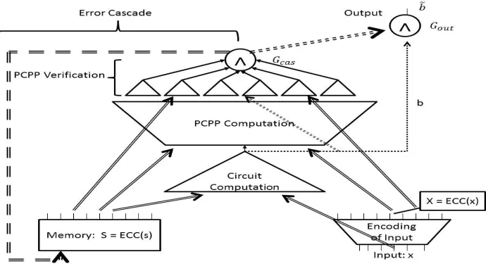
The compiled circuitCS(1)is depicted in Figure 1.
Fig. 1. The compiled circuitCS(1).We show here the Memory and the4segments of the compiled circuit. Note that the encoding
Sand the inputxare fed into the Circuit Computation Stage of Segment1. Additionally, the encodingsSandX are fed into the PCPP Computation Stage of Segment1, and are fed to Segment2(the PCPP Verification Stage) along with the bitb, the output of the Circuit Computation Stage. The outputs ofGcasfeed back into memory (this is Segment3–Error Cascade) and to the final
output gateGout(in Segment4) along with the output bitbof the Circuit Computation Stage. The final output of the circuit is˜b.
The circuitCS(1)is secure against an adversaryAwho may tamper as follows:
– Acan tamper with any number of wires in Segment1of the circuit (which consists of the encoding computation of the inputx, the circuit computationCs(x), and the PCPP computation).
6
– Acan tamper with at mostλ-fraction of the wires in Segment2(PCPP verification),λ-fraction of the wires in Segment3(error cascade),λ-fraction of the wires in Segment4(output segment) and with at mostλ-fraction of the memory gates, whereλ= min{ 1
3 ˜σV, δ
6}.
We call such an adversaryλ-locally tampering, and we denote the output of any such adversary byLocalTAMPA(C
(1)
S ).
Lemma 1. Letλ= min{ 1 3 ˜σV,
δ
6}. Then for anyλ-locally tamperingadversaryAthere exists a simulatorSim, that
runs in timepoly(|A|,|Cs|), such that
{LocalTAMPA(C
(1)
S )}k∈N≡ {LeakBBSim,logT(Cs)}k∈N, whereTis an upper bound on the number of times thatAruns the (tampered) circuit.
In what follows, we give the high-level idea of the proof of Lemma 1, followed by the formal proof.
Proof idea. Fix anyλ-locally tamperingadversaryA. LetTbe an upper bound on the number of times the adversary
Aruns a possibly tampered version of the circuitCs(1). We construct a simulatorSimwith black-box access toCs,
which is allowed to requestlogTbits of leakage on the secrets, and simulates the view ofA.
Simchooses the leakage function to be the functionL :{0,1}k → {0,1}logT, which has the adversaryA
hard-wired into it, and on input a secrets, outputs the largest indexi∗, such that in the first i∗−1 runs of the (possibly tampered) circuit byA, all the (possibly tampered) input wires to the gateGcashave the value1.
After querying this leakage function and receiving an outputi∗,Siminternally emulatesA, by emulating the output of each run of the circuit. Each timeAcalls the circuit with inputxiand a set of tampering instructions, the simulator Simsimulates the run of the (possibly tampered) circuit as follows:
– Simulate the output Xi0 of the (possibly tampered) Encoding Input Segment. Efficiently decode Xi0 to obtain
x0i=Dec(Xi0). Note thatX0
imay be far from a codeword, in which casex0imay be⊥. Also, note that the simulatorSimis indeed
able to carry out the above computation exactly as in the real computation, since this part of the computation does not use the secrets, and sinceSimknowsA’s tampering instructions.
– Ifi < i∗, set all the input wires ofGcasto be1, and set the output of the Circuit Computation Segment to be b0i=Cs(x0i). As we prove in Section 4.1, the fact thati < i∗implies that it must be the case thatx0i6=⊥, and that the output of the Circuit Computation Segment is indeedCs(x0i).
Simulate the outputboutofGout, using the tampering instructions ofA, assuming that the values of theK+ 1
incoming wires (before applying the tampering instructions to these wires) are(1K, b0
i). Returnbout.
Note that it is not necessarily the case thatbout=b0isince the adversaryAmay tamper with some of the incoming
wires ofGoutand may tamper with the output wire.
– Ifi≥i∗, returnbout= 0, unlessAtampers with the output wire, in which caseSimreturnsbif the tamper is “set
tob”, and returns1if the tamper is “toggle”.
We will argue that in this case, even ifAtampers with the input wires toGout, the output ofGoutis always going
to be0, since he cannot tamper with all the input wires (recall that he can tamper with at most aλ-fraction of the wires). Thus, the output wire is always0, unless the output wire itself is tampered with.
Proof of Lemma 1. Fix someλ-locally tamperingadversaryA. LetT be an upper bound on the number of times the adversaryAruns a possibly tampered version of the circuitCs(1). We construct a simulatorSimwith black-box access
toCs, which is allowed to requestlogTbits of leakage on the secrets, and simulates the view ofA. Simchooses the leakage function to be the function
L:{0,1}k → {0,1}logT,
which has the adversaryAhard-wired into it, and on input a secrets, outputs the largest indexi∗, such that in the first
i∗−1runs of the (possibly tampered) circuit byA, all the (possibly tampered) input wires to the gateGcashave the
value1.
– Simulate the output Xi0 of the (possibly tampered) Encoding Input Segment. Efficiently decode Xi0 to obtain
x0i=Dec(Xi0).
Note thatXi0may be far from a codeword, in which casex0imay be⊥. Also, note that the simulatorSimis indeed able to carry out the above computation exactly as in the real computation, since this part of the computation does not use the secrets, and sinceSimknowsA’s tampering instructions.
– Ifi < i∗, set all the input wires ofGcasto be1, and set the output of the Circuit Computation Segment to be b0
i=Cs(x0i). As we later claim, for everyi < i∗it must be the case thatx0i6=⊥, and that the output of the Circuit
Computation Segment is indeedCs(x0i).
Simulate the outputboutofGout, using the tampering instructions ofA, assuming that the values of theK+ 1
incoming wires (before applying the tampering instructions to these wires) are(1K, b0
i). Returnbout.
Note that it is not necessarily the case thatbout=b0isince the adversaryAmay tamper with some of the incoming
wires ofGoutand may tamper with the output wire.
– Ifi≥i∗, returnbout= 0, unlessAtampers with the output wire, in which caseSimreturnsbif the tamper is “set
tob”, and returns1if the tamper is “toggle”.
We will argue that in this case, even ifAtampers with the input wires toGout, the output ofGoutis always going
to be0, since he cannot tamper with all the input wires (recall that he can tamper with at most aλ-fraction of the wires). Thus, the output wire is always0, unless the output wire itself is tampered with.
Before analyzing the output distribution ofSim, we present the following claim:
Claim. For thei’th run of the (tampered) circuit byA, letSi0denote the memory contents, letXi0denote the output of the Encoding Input Segment, and letbidenote the output of the Circuit Computation Segment.7If all the input wires to
Gcashave the value1, then it must be the case that(Xi0◦Si0)isρ-close to some(Xi00◦S00i)for which(bi, Xi00◦Si00)∈ L.
Proof. Recall thatAcan tamper with at most aλ-fraction of the wires in Segment2, and recall that the number of wires in Segment2 isσv = ˜σv·τ (whereσ˜v is the number of wires in each PCPP verifier, andτ is the number of
possible PCPP verifiers). Thus,Acan tamper with at mostλ·σ˜v·τ≤ τ3 wires in Segment2, and therefore can tamper
with at most1/3of the PCPP verifiers. This, together with the fact that all the input wires toGcasare1, implies that
in runi, at least2/3of the PCPP verifiers are not tampered with and output1.
Thus, by the soundness of the PCPP (which is1/2), we must have that(Xi0◦Si0)isρ-close to some(Xi00◦Si00)for which(bi, Xi00◦S00i)∈ L, as desired.
We next argue that the random variableLeakBBSim,logT(Cs), which is the output ofSim, and the random variable
LocalTAMPA(C
(1)
S ), which is the output ofA, areidenticallydistributed. To this end, it is sufficient to argue that the
output of the tampered circuit and the output ofSimare the same for all the runs of the circuit. There are two cases to consider:
Runifori < i∗:In this case,Simsets all the input wires ofG
casto1, which must be correct sincei < i∗.Simalso
sets the output of the Circuit Computation segment to beb0i =Cs(x0i), and simulates the output of the gateGout
exactly is in the real world execution ofA, assuming that the input wires to the gateGouthave the values(1K, b0i),
before applying the tampering instructions to these wires.
Letbidenote the output of the Circuit Computation Segment in the real experiment run byA. The value outputted
bySimdiffers from the value outputted by the tampered circuit only ifbi6=Cs(x0i). We next show that this cannot
be the case.
The fact that all the input wires ofGcasare1 fori < i∗, together with Claim 4.1, implies that for alli < i∗,
(Xi0◦Si0)isρ-close to some(Xi00◦Si00)for which(bi, Xi00◦Si00)∈ L.
This implies, in particular, that for alli < i∗,Xi0andSi0are2ρ-close to the codewordsXi00andSi00, respectively. This follows from the fact thatXi0andSi0are of the same size. The fact that2ρ < δimplies thatx00i =x0i, where
xi00is defined so thatECC(x00i) =Xi00(and in particular thatx0i6=⊥).
We next claim that Si00 = S = ECC(s) for all i < i∗. We note that this claim, together with the fact that (bi, Xi00◦Si00)∈ L, implies that indeedbi=Cs(x00i) =Cs(x0i) =b0ifor alli < i∗.
7
Assume towards contradiction that there is somei < i∗such that Si00 =ECC(˜s)ands˜6=s. Letj < i∗ be the
firstsuchi. Thus,Sj0 andECC(˜s)are2ρ-close. We first argue that it cannot be the case thatj = 1. This follows from the fact that the adversary can tamper with at mostλ-fraction of the memory, and thusS0
1must beλ-close
toECC(s). If it was also2ρ-close toECC(˜s), then it would imply thatECC(s)andECC(˜s)are(2ρ+λ)-close, contradicting the distance property ofECC, since2ρ+λ < δ
3+
δ
6 < δ. Therefore it must be the case thatj >1.
In particular, this implies thatSj0−1andECC(s)are2ρ-close.
The fact thatj < i∗implies that Error Cascade Segment (at the end of runj−1) can overwrite at mostλ-fraction of the memory. Moreover, the adversary in runjcan tamper with at mostλ-fraction of the memory gates. Thus,
S0j−1andSj0 are2λ-close. We conclude thatECC(s)andECC(˜s)are(4ρ+ 2λ)-close, contradicting the distance property of theECC, since4ρ+ 2λ < 4δ
6 +
δ
3 =δ.
Runifori ≥i∗:Suppose that one of the input wires ofGcasis0(and thusGcasoutputs02Kbefore applying the
tampering instructions to these wires). IfAdoes not tamper with the output wire, then it must be the case that the output of the tampered circuit is 0. This is the case since Acan only tamper with λ-fraction of the wires in Segment4, and thus cannot tamper with all theK input wires ofGout (which are all0before applying the
tampering instructions to these wires). IfAdoes tamper with the output wire, thenSimreturnsbif the tamper is “set tob”, and returns1if the tamper is “toggle”. Thus,Simindeed perfectly simulates the output of the circuit in the case where one of the input wires ofGcasis0. Therefore, it suffices to argue that for alli > i∗, one of the
input wires ofGcasis0, assuming this is the case fori∗.
Assume towards contradiction that for somei > i∗, all the input wires ofG
casare1. Letj > i∗be the smallest
such index. Namely, assume that in thej−1’st run one of the input wires ofGcasis0, and yet in thej’th run all
the input wires ofGcasare1.
Again, using Claim 4.1, we have that in thej’th run(Xj0◦Sj0)isρ-close to some(Xj00◦Sj00)for which(bj, Xj00◦ S00j)∈ L. This implies, in particular, thatS0jis at least2ρ-close to some codeword.
However, since in runj −1, one of the input wires ofGcaswas0, we have that at the end of roundj−1, the
memorySj0−1was updated so that at least1−λfraction of the memory gates are overwritten with zeros. This is the case sinceAcan tamper with at mostλ-fraction of the wires in the Error Cascade Segment, where each such wire is used to update a memory gate. This, together with the fact that in runjthe adversaryAcan tamper with at mostλ-fraction of the memory, implies thatS0
jis(1−2λ)-close to0K.
On the other hand, due to the distance property ofECC, any valid codewordSj00can have at most a(1−δ)-fraction of positions set to0.8Thus,S0
jdiffers from any codeword in at least(δ−2λ)-fraction of positions, contradicting
the fact thatδ−2λ≥δ−δ
3 = 2δ
3 >2ρ.
u t
4.2 The Compiler: Second Construction
Note thatCS(1)is secure against any adversary that tampers with only a constant fraction of the memory, and a constant fraction of the wires in Segments2,3and4. We would like to construct a circuit that is secure against adversaries that tamper with a constant fraction of the circuit overall. Namely, we would like our circuit, which will be denoted by
C(2)˜
S , to have the property that there is a constantλ >0such thatC
(2) ˜
S is secure against any adversary that for each
run of the circuit sends at mostλ· |CS(2)˜ |tampering instructions, where each tampering instruction is either a wire tampering or a memory tampering.
We do this by adding enough memory gates, and enough wires to the critical segments: the PCPP Verification Segment, the Error Cascade Segment and the Output Segment, so that the following two conditions hold.
1. Each of these segments, as well as the memory, remains resilient to a constant fraction of tampering.
2. The total number of wires in each of these segments, and the size of the memory, is a constant fraction of the total number of wires in the entire circuit.
More specifically, letσcomp =σcomp(k)be the size of Segment1of the circuitC
(1)
S . We transform the circuitC
(1)
S ,
to ensure that the sizeK = K(k)of the encoding ofsin memory, the sizeσv = σv(k)of Segment2 (the PCPP
8
Verification Segment), the sizeσcas=σcas(k)of Segment3(the Error Cascade Segment), and the sizeσout=σout(k)
of Segment4(the Output Segment), satisfy
Θ(K(k)) =Θ(σv(k)) =Θ(σcas(k)) =Θ(σout(k)) =Ω(σcomp(k)),
without changing the sizeσcompof Segment1, and while keeping each of the above segments (Segments2,3, and4),
and the memory gates, resilient to constant fraction of tampering.
This transformation will allow us to prove security against adversaries who tamper with a constant fraction of the circuit overall. We proceed with the formal construction.
Let
M =M(k) = max{σv(k), K(k), σcomp(k)}.
Letp1(k),M/σv(k), and letσv0(k),p1(k)·σv(k). Similarly, letp2(k),M(k)/K(k), and letK0(k),p2(k)·
K(k). For the sake of simplicity we assume thatp1andp2are integers.9Note that under this simplifying assumption
K0=σv0 =M.
In what follows we give a formal description of our second compiler, which takes as input a (private) circuitCs
and outputs a (private) circuitC(2)˜
S , defined as follows.
Memory: Encoding Secrets.LetECC(g s) = ECC(s)p2(k), where byECC(s)p2(k)we denotep2(k)concatenated
copies ofECC(s). Note thatECCg is an error-correcting code which has the same distance asECC, which is at
least2δ. (The reason the distant ofECCis at least2δfollows from the fact that it can correct up toδ-fraction of errors.) LetS˜=ECC(g s). We denote byS˜(i, j)thej-th bit of thei-th copy ofS. We denote bySthe first row of
the encodingS˜:( ˜S(1, j))j∈[K]. The encodingS˜is placed in the memory ofC(2).
Segment1.This segment, which includes the encoding of the inputx, the circuit computation, and the PCPP com-putation, remains exactly the same as Segment1ofCS(1). In order to keep this segment the same, instead of using
the entire new memoryECC(^S), this segment only uses the first row ofECC(^s), which is exactlyS =ECC(s), the memory content ofC(1).
Segment2: PCPP Verification.This stage consists ofτ0,p1(k)·τnumber of circuits{Cvi,j}i∈[τ],j∈[p1(k)], where
each PCPP verifier fromCS(1) is simply copiedp1(k)times. Namely, for eachi∈ [τ]and eachj ∈[p1(k)], the
circuitCvi,jis simply a copy ofCvi. We note that eachCvi,jonly accesses the first row of memoryS= ( ˜S1,j)j∈[k],
and as before, each verifier circuitCvi,j takes as input a constant number of bits from(X◦S, b, π)and outputs a
single bitβi,j. Note that each verifier circuit still has constant sizeσ˜v.
All theseτ0output wires of the circuitsCvi,j are inputs to the AND gateGcas. This gate hasK
0additional input
wires that belong to Segment 3 below (whereK0 is the number of bits inS˜). The gate Gcas has 2K0 output
wires, and we denote the values on these wires by{γ`,m}i∈[p2(k)],j∈[2K]. The firstK
0output wires (with values
{γ`,m}i∈[p2(k)],j∈[K]) belong to Segment3, and the otherK
0output wires belong to Segment4.
Segment3: Error Cascade.This segment has two parts:
– A circuitCcodei,j of constant sizeσcodefor each bitSi,j˜ ofS˜:1≤i≤p2(k),1≤j ≤K:
Input:S˜(1, j),S˜(i, j).
Output:ψi,j=q( ˜S(1, j)⊕S˜(i, j)).
All these output wires with valuesψi,jare inputs toGcas. Thus, in total,GcashasK0+τ0input wires (τ0from
Segment2andK0from Segment3), and it outputs
^
i∈[τ],j∈[p1(k)] βi,j
∧
^
i∈[ps(k)],j∈[K]
ψi,j
9
This simplifying assumption makes the analysis somewhat cleaner. Without this assumption, we would need to definep1(k),
– The first K0 output wires of Gcas, denoted by (γ`,m)`∈[p2(k)],m∈[K], are fed to the memory gates. More
specifically, for every` ∈ [p2(k)]andm ∈ [K], the(`, m)-th outputγ`,m ofGcasis the input to memory
gate(`, m). Thus, ifγ`,m= 0, memory position(`, m)is overwritten with a0. Ifγ`,m= 1, memory position
(`, m)is unchanged.
Segment4: The Output.This segment of the circuit consists ofK0 output wires ofG
cas, which have the values {γ`,m}`∈[p2(k)],m∈[K+1,2K]. This segment has a single AND gateGoutwhich has fan-inK
0 + 1. This segment
contains all theK0+ 1input wires toGout: The firstK0input wires are exactly theK0output wires ofGcas(with
values{γ`,m}`∈[p2(k)],m∈[K+1,2K]), and the other input wire ofGoutis an output wire of the Circuit Computation
in Segment1, which computes the bitb=Cs(x). The AND gateGouthas a single output wire which is
˜
b=b∧
^
`∈[p2(k)],m∈[K0+1,2K0] γ`,m
.
The final output of the circuitC(2)˜ S (x)is
˜
b.
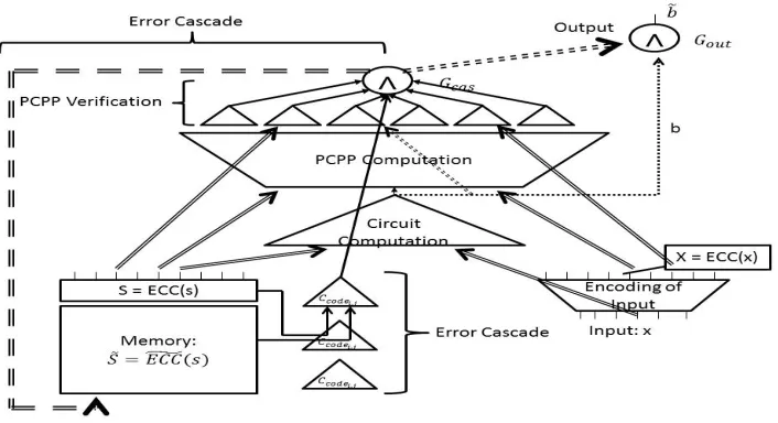
The compiled circuitC(2)˜
S is depicted in Figure 2.
Fig. 2. The compiled circuitCS(2)˜ . We show here the Memory and4segments of the compiled circuit. Note the differences betweenCS(2)˜ andC
(1)
S : First, the encodingS˜=ECCg(s)is placed in memory and the size of memory is increased. Second, the size of Segment2(PCPP Verification), Segment3(Error Cascade), and Segment4(Output), is increased. Third, the constant-size circuitsCcodei,jare added to check consistency of the encoding. The outputs of these circuits are then all inputted toGcas.
Recall that we denote byσ0v=σv0(k)the size of the PCPP Verification Segment inC(2)˜
S , and we denote byK
0the
number of memory gates inC(2)˜
S . We also denote byσ
0
cas =σ0cas(k)the size of the Error Cascade Segment inC
(2) ˜
S
and denote byσ0
out=σ0out(k)be the size of the Output Segment inC
(2) ˜
S . It follows by construction that
Θ(σv0(k)) =Θ(σ0cas(k)) =Θ(σ0out(k)) =Θ(K0(k)) =Ω(σcomp(k)),
as desired.
Let
α=α(k) = min
σ0v(k) σ0(k),
σ0cas(k) σ0(k) ,
σout0 (k) σ0(k)
.
Note thatα(k) =Θ(1).
Theorem 3. Letλ0= min{α 1 3 ˜σv, α
δ
6σcode}. ThenC
(2) ˜
S is secure againstλ
0-tampering adversaries (as defined in
Defi-nition 5).
In what follows we prove Theorem 3. We note that in the proof we use that fact that everyλ0-globally tampering
adversary inC(2)˜
S is also aλ= min{
1 3 ˜σv,
δ
6σcode}-locally tamperingadversary inC
(2) ˜
S .
Proof. We prove the stronger statement that, in fact forλ= min{ 1 3 ˜σv,
δ
6σcode}, it holds that for everyλ-locally
tamper-ingadversaryAthere exists a simulatorSimsuch that
{TAMPA(CS(2)˜ )}k∈N≡ {LeakBBSim,logT(Cs)}k∈N,
whereTis an upper bound on the number of times thatAruns the tampered circuit. This suffices to obtain our theorem since anyλ0-tampering adversary is in particularλ-locally tampering.
We fix anyλ-locally tampering adversaryA, and we construct a simulatorSimwith black-box access toCs, which is allowed to requestlogT bits of leakage.
The leakage functionLchosen bySimis the same function as in the proof of Lemma 1, but with respect to the circuitC(2)˜
S instead ofC
(1)
S . Namely, the leakage function
L:{0,1}k → {0,1}logT,
has the adversaryAhard-wired into it, and on input a secrets, outputs the largest indexi∗, such that in the firsti∗−1 runs of the (possibly tampered) circuit byA, all the (possibly tampered) input wires to the gateGcashave the value1.
The simulator simulatesAexactly as is done in the proof of Lemma 1. Namely, each timeAcalls the circuit with inputxiand a set of tampering instructions, the simulator simulates the output as follows: It simulates the outputXi0
of the (possibly tampered) Encoding Input Segment, and computes the decodingx0i=Dec(Xi0).10
Ifi < i∗, the simulatorSimsets the value of all the input wires ofGcasto be1, and sets the output of the Circuit
Computation Segment to beb0i=Cs(x0i). Then, it simulates the outputboutofGout, assuming that theK0+1incoming
wires (before applying the tampering instructions to these wires) have values(1K0, b0
i).
Ifi ≥i∗thenSimreturns bout = 0, unlessAtampers with the output wire, in which case Simreturns bif the
tamper is “set tob”, and returns1if the tamper is “toggle”.
Before analyzing the output distribution ofSim, we present the following claim:
Claim. For thei’th run of the (tampered) circuit byA, letS˜i0denote the contents of memory, letXi0denote the output of the Encoding Input Segment, and letbi denote the output of the Circuit Computation Segment.11 If all the input wires toGcashave the value1, then the following two conditions hold:
(1) (Xi0◦Si0)isρ-close to some(Xi00◦Si00)for which(bi, Xi00◦Si00)∈ L, whereSi0,( ˜S0i(1, j))j∈[K]is the first row
ofS˜i0.
(2)SupposeSi00=ECC(s∗).12ThenS˜0
iis(2ρ+δ/3)-close to the codewordS˜i00=ECC(g s∗).
10
Note thatXi0may be far from a codeword, in which casex
0
imay be⊥. 11
We emphasize thatS˜i0, Xi0, b0iare the values obtainedafterapplying the tampering instructions of thei’th run. 12
Note that the fact that(bi, Xi00◦S
00
i) ∈ Limplies thatS
00
i is indeed a codeword, and hence there must exists
∗
such that
Proof. We first prove Condition(1), whose proof is essentially the same as the proof of Claim 4.1. Assume towards contradiction that(Xi0◦Si0)isρ-far from every(Xi00◦Si00)for which(bi, Xi00◦Si00)∈ L. Recall thatAcan tamper with at mostλ-fraction of the wires in Segment2. Note that now the size of Segment2isσ0
v = ˜σv·τ·p1 (where
˜
σvis the size of each PCPP verifier, andτ·p1is the number of PCPP verifiers). Thus,Acan tamper with at most
λ·σ˜v·τ·p1≤ p13·τ wires in Segment2. This, together with the fact that all the input wires toGcasare1, implies that
in runi, at least2/3of the PCPP verifiers are not tampered with and output1.
Thus, by the soundness of the PCPP (which is1/2), we must have that(Xi0◦Si0)isρ-close to some(Xi00◦Si00)for which(bi, Xi00◦S00i)∈ L, as desired.
We next prove Condition(2). We start by noting that Condition(1)implies thatSi0is2ρ-close to some codeword
Si00=ECC(s∗). This follows from the assumption that|X0
i|=|Si0|. Assume for the sake of contradiction thatS˜i0is not
(2ρ+δ/3)-close toS˜i00=ECC(g s∗). Then it must be the case that(Si0)p2(k)andS˜i0are notδ/3-close, since(Si0)p2(k)is
2ρ-close toECC(g s∗). Consider theK0wiresψi,jwhich are all inputted to the AND gateGcas. It must be the case that δ/3-fraction of these wires have the value0(before applying the tampering instructions to these wires). Thus,δK0/3 of these input wires toGcashave value0(before applying the tampering instructions to these wires). However,Acan
tamper with at mostλ≤ δ
6σcode-fraction of the total number of wires in Segment3, where the total number of wires in Segment3is
σ0cas=σcode·K0+K0.
Thus,Acan tamper with at most
δK0/6 + (δK0)/(6σcode)< δK0/6 +δK0/6 =δK0/3
of the wires in Segment3. So even after tampering, at least one of the input wires toGcaswill be0, contradicting the
assumption that for everyi < i∗all the (possibly tampered) input wires toGcasare1.
To argue that the output of the simulatorSimis identically distributed to the output ofA, we distinguish between two cases:
Runifori < i∗:In this case, to prove correctness of the simulation we need to prove that in the real run ofA, it holds thatx0i6=⊥and that the output of the Circuit Computation Segment isbi=Cs(x0i).
Recall that for alli < i∗, all the (possibly tampered) input wires ofGcashave the value1. This, together with
Con-dition(1)of Claim 4.2, implies that for alli < i∗,Xi0andSi0are2ρ-close to codewordsXi00andSi00, respectively. The fact that2ρ < δimplies thatx00i = x0i, wherex00i is defined so thatECC(x00i) = Xi00(and in particular that
x0
i6=⊥).
We next claim that S˜i00 = ˜S = ECC(g s)for alli < i∗. We note that this claim, together with Condition (1)of
Claim 4.2 (which guarantees that(bi, Xi00◦Si00)∈ Land thatx00i =x0i), implies that indeedbi=Cs(x00i) =Cs(x0i) for alli < i∗, as desired.
Condition(2)of Claim 4.2 implies that for everyi < i∗,S˜i0is(2ρ+δ/3)-close to some codewordS˜i00=ECC(g s0).
Assume that for somei < i∗,s0 6=s, and letj < i∗be thefirstsuchi. We first note that it must be the case that
j > 1. This follows from the fact thatS˜10 isλ-close toS˜ = ECC(g s). Moreover, the distance between any two
codewords inECCg is at leastδ, and thusS˜10 is(δ−λ)-far from any other codeword, whereδ−λ >56δ is greater
than2ρ+δ/3 = 26δ +δ3 =23δ.
Thus,j > 1. Namely, on the one hand,S˜0jandECC(g s0)are(2ρ+δ/3)-close; and on the other hand,S˜j0−1and
g
ECC(s)are(2ρ+δ/3)-close. This together with the fact that every two codewords are2δ-far (follows from the fact thatECCg can correct up toδerrors), implies thatS˜j0−1andS˜j0 are(2δ−4ρ−23δ)-far, where2δ−4ρ−23δ =
2δ−2δ
3 − 2δ
3 = 2δ
3.
We reach a contradiction by arguing thatS˜j0−1andS˜j0 are δ2-close. At the end of thej−1’st run of the (possibly tampered) circuit, the memoryS˜0j−1 may be updated. We argue that at most λ(K0 +K0σcode)of the memory
gates are overwritten. This is the case sincej−1 < i∗, and thus all theK0 wires updating the memory (which are output wires of Gcas) are1 before applying the tampering instructions to these wires. Note that these K0
wires belong to Segment3of the circuit, a segment which consists ofK0 +K0σcodewires. Since the adversary
λ(K0+K0σcode)of theK0wires that update the memory. Moreover, note thatAcan tamper with the values of
at most aλ-fraction of positions in memory during thej’th run. Thus, all in all,S˜j0−1andS˜j0 differ in at most
λ(K0+K0σ
code) +λK0memory locations, where
λ(K0+K0σcode) +λK0=λK0σcode+ 2λK0 ≤ δK0
6 +
δK0
3 =
δK0
2 (4.1)
(follows from the fact thatλ≤ δ
6σcode).
Thus, we conclude thatS˜j0−1andS˜j0 are δ2-close, in contradiction to the above.
Run ifori ≥i∗:As was argued in the proof of Lemma 1, if one of the (possibly tampered) input wires ofG cas
has the value0then the simulation is correct. Thus, it suffices to argue that indeed one of the (possibly tampered) input wires ofGcashas the value0in each runi≥i∗. Assume towards contradiction that there existsj > i∗such
that in thej’th run all the (possibly tampered) input wires ofGcashave the value1, and yet in thej−1’st run one
of the (possibly tampered) input wires ofGcashas the value0.
Condition(2)of Claim 4.2 states that if in runj, all the (possibly tampered) input wires ofGcashave the value1,
thenS˜0jis(2ρ+δ/3)-close to some codewordS˜j00=ECC(g s00). Moreover,ECCg had distance2δ, and thus any valid
codewordS˜j00can have at most a(1−2δ)-fraction of positions set to0.13 This implies thatS˜0
j can have at most
(1−2δ+ 2ρ+δ/3)-fraction of positions set to0, where
1−2δ+ 2ρ+δ/3 = 1−2δ+2δ 3 = 1−
4δ
3 .
Thus,S˜0
jis43δ-far from0
K0.
On the other hand, the fact that in runj−1, one of the (possibly tampered) input wires ofGcashas the value0,
implies that at the end of roundj−1, at leastλ(K0+K0σcode)of the memory gates are overwritten and set to0. This
is the case since theK0wires updating the memory all have the value0before applying the tampering instructions to these wires. These wires belong to Segment3of the circuit, a segment which consists ofK0+K0σ
codewires.
Thus, the adversary can tamper with at mostλ(K0+K0σ
code)of these wires. In addition the adversary can tamper
with at mostλ-fraction of the memory gates in thej’th run, and thusS˜0jcan have at mostλ(K0+K0σcode)+λK0≤ δK0
2 non-zero memory gates (see Equation (4.1)). Hence,S˜
0
jisδ2-close to0
K0, contradicting the fact that it is4δ
3-far
from0K0.
5
Dealing with Large Fan-out
In practice, circuit gates do not have large fan-out. Rather, gates have a single output wire which is then inputted into a device called asplitterthat replicates the wire many times. We now consider a model where all gates have fan-out1 (possibly feeding into splitters) and where each input and output wire of a splitter may be individually tampered with. It is not hard to see that we can safely replace all gates with large fan-out in our construction with splitters,except
for the gateGcas. Indeed, if we modify the high fan-out gateGcasto have a a single output wire and a splitter then the
adversary can simply set the value of the single output wire ofGcasto1in each run of the circuit, and thus prevent
self-destruct from occuring, which means that security cannot possibly hold.
In order to ensure that each gate has a single output wire (which is possibly fed into a splitter), we eliminate the
Gcasgate altogether, and modify the rest of the circuit. Intuitively, we add an additional matrixM to the memory,
which is initialized to 1 and it ”keeps track” of whether self-destruct has previously occurred. When self-destruct occursM is overwritten by0’s. Moreover, we will show how to construct a circuit on top ofM in such a way that onceM is set to have a large constant fraction of0’s in some run`,M is guaranteed to have a large constant fraction of0foreveryruni > `.
More specifically, we add to the memory a matrixM of sizep2(k)×K=K0with entries all initialized to1. We
use an expander graph to update the memoryM.
13
Recall that we assume thats= 0kis not a valid seed, and thusECCg(0k) = 0K
0
Consider a bipartite expander graph GM of constant degreedon vertex set(Mafter, Mbefore)where|Mafter| = |Mbefore| = K0. For eachi, j, the verticesMbefore
i,j , M after
i,j are identified with memory locationMi,j. Intuitively, the
vertex setMbeforecorresponds to the memory locations and values before some runiandMafter corresponds to the memory locations and values after runihas completed. For every edge between two verticesMi,jafterandMk,`beforeinGM
we connect the output ofMk,`to the input ofMi,j. Ultimately, each memory gateMi,jwill have a constant number
(d) of input wires and will be ”zeroed out” iff at least one of its input wires is set to0. Note that since degreedis a constant, total number of wires added to our previous construction isd·K0 =Θ(K0).
A high-level overview of the construction is presented below. We present the Segments of the circuit in the order in which they are computed. Namely, the output of Segment4is computed before Segments2and3. Details follow.
Memory: Encoding ofsand1string.In addition toS˜=ECC(g s)in memory, where|S|˜ =K0, we add to memory
a matrixMof sizep2(k)×K=K0with entries all initialized to1.
We denote the(i, j)’th position inS˜bySi,j˜ and the(i, j)’th position inM byMi,j.
Segment1.This segment, which includes the encoding of the inputx, the circuit computation, and the PCPP com-putation, remains the same as Segment1ofC(2)˜
S .
Segment 4: The Output. The AND gateGout hasK0 + 1 input wires. The first K0 input wires are the output
wires from each memory gateM(i, j)with valuemi,j. The last input wire is the output wire from the circuit
computation in Segment1 with valueb. The gateGout outputs 2K0+ 1 wires (i.e. a single output wire and a
splitter into2K0+ 1wires) with value:
˜b=b∧
^
i∈[p2(k)],j∈[K] mi,j
.
2K0 of the output wires are inputted to their respective PCPP Verifiers. The remaining wire is the final output value of the circuit.
Segment2: PCPP Verification.We increase the number of verifiers so there are exactlyK0 number of verifiers. Otherwise, this segment remains exactly the same as Segment2ofC(2)˜
S , with the following exceptions:
– Each PCPP Verifier circuitCvi,j takes the input bit˜bfrom the output of gateGout, instead of taking the bitb,
from the Circuit Computation Stage in Segment1.
– The output wires of the PCPP Verifier circuitsCvi,j with values{γi,j}i∈[p2[k]],j∈[K] are not inputted to the
gateGcas, but rather directly to memory gatesM (see Segment3below).
Segment3: Error Cascade.This segment has two parts as before:
– The first part is the same as in the previous construction, except that all the output wires ofCcodei,j with
valuesψi,jare fed into the second part of memory. More specifically, the output wire ofCcodei,j is inputted
to memory locationMi,j. – TheK0 output wires ofC
vi,j, with values(γi,j)are fed to the memory gates. More specifically, for every i∈ [p2(k)]andj ∈[K], the(i, j)’th outputγi,j is the input to memory gateSi,j˜ and for everyi∈ [p2(k)]
andj∈[K], the(i, j)’th outputγi,jis the input to memory gateS˜i,j.
– Finally, we specify the wiring on the memory gatesM induced by the edges of the expander graphGM. For every pair of memory gatesMi,j,Mk,`, there is a wire going from the output ofMk,`to the input ofMi,jiff there is an edge betweenMafter
i,j andMk,`beforeinGM
We now give some intuition for why this construction is secure. The leakage function used by the simulator is now slightly different. The simulator asks for the largest indexi∗, such that in all runsi < i∗, the value of the (possibly tampered) single output wire of the gateGout is the “correct” value; i.e., it isCs(x0), wherex0 is the input extracted
by the simulator, as described in the simulation in the proof of Theorem 3 andsis the original secret.
Note that simulating runsi≤i∗is easy, since knowing the output ofGout, the simulator can perfectly simulate the
final output of the circuit, by observing the tampering instructions that are made to the final output wire of the circuit. For the simulation of runsi > i∗, we prove that for every runi > i∗, it must be the case that at least one (possibly tampered) input wire toGouthas the value0. Once we establish this, again simulating becomes easy since the simulator