IJEDR1502020
International Journal of Engineering Development and Research (www.ijedr.org)103
Finite Element Analysis of Pressure Vessels by
different Elements
1Vidyadhar Reddy Potham, 2Ravikrishnamoorthy.S 1M.Tech Student, 2Assistant Professor(S.G), 1,2
School of Mechanical Engineering, SRM University, Chennai
________________________________________________________________________________________________________
Abstract - This paper presents applicable methods available using finite element analysis (FEA) in the field of study of
pressure vessel. Discontinuity stresses in cylindrical pressure vessel connected to flat and hemispherical heads with internal pressure are determined by using principles specified in American Society of Mechanical Engineers (A.S.M.E) sec VIII division 1. In the present study 3D, axi-symmetric and symmetric models of pressure vessels are analyzed using ANSYS. The three models and the type of elements used are 3D model with solid elements, axi-symmetric model using plane elements, symmetric model using shell elements. Theoretical values obtained by discontinuity analysis are checked with ansys results and best methods in pressure vessel analysis are stated. Contact elements were tested to determine their usefulness in modeling the interaction between pressure vessel cylinder walls and heads. When modeled correctly, contact elements proved to be useful, but the operator also needs to be able to interpret the results properly. Problems such as local stress risers, unrealistic displacements and understanding how to use such data become extremely important in this kind of analysis. This highlights the key to proper use of finite element analysis. The analyst should be able to approximate the solution using classical methodology (hand calculations) in order to verify the solution.
Keywords-Pressurevessel, Finite element analysis,Discontinuity stresses
________________________________________________________________________________________________________
I. Introduction
Cylindrical pressure vessels are widely used in many engineering applications. Power and nuclear plants, and food and petrochemical industries are some examples of applications of such equipments. Pressure vessel cylindrical intersections are defined as the transition between the cylindrical shell and the head, and constitute a critical area, normally the weakest part of the vessel. Due to geometric discontinuities, this region presents high stress concentration levels and it is where failure is more likely to occur. For pressure vessel long life warranty, Pressure Vessels Codes and Standards, such as the ASME Boiler & Pressure Vessel Code or the BS5500 Unfired Fusion Welded Pressure Vessels (BS 5500), among others, establish rules and methods for analyzing the pressure vessels and their components. Other way to evaluate the stress fields is to perform numerical analysis using computational tools (like ANSYS).
A. Discontinuity Analysis:
In the design of pressure vessels, certain regions frequently exist where continuity of the structure cannot be satisfied by membrane forces alone. Such regions are known as discontinuity areas. Determination of discontinuity stresses is an important problem, i.e. the design of pressure vessels. Discontinuity stress can arise from three basic sources:
⇒Geometric discontinuity: abrupt change in radius of curvature and/or thickness of the shell; ⇒Material discontinuity: abrupt change in mechanical properties;
⇒Load discontinuity: abrupt change in load intensity of static loading - line load.
It will be clear that at the junctions, their undisturbed displacements need not correspond with each other and that there is certainly no equilibrium. By introducing so-called edge forces and edge moments on both edges (in total four unknowns), the equilibrium and the continuity in displacement and rotation are restored and these unknowns can be solved from equations describing the equilibrium and continuity. This requires of course knowing the behaviour of both cylindrical shell as well as heads under the action of an edge force and an edge moment. For relatively thin shells, such equations are available based on shell theory in ASME VIII DIV.2.[6]
Having found the edge forces and edge moments, the stresses locally at the junction in both the cylindrical shell as well as in the heads can be determined. For the full details on the equations to be solved, one is referred to Appendix A.[6]
B. Finite Element Analysis:
IJEDR1502020
International Journal of Engineering Development and Research (www.ijedr.org)104
analysis is that it is one of the main activities that can give a designer a quantitative yard-stick as to the efficiency of a load carrying component and the possibility of its failure in service. It is thus a necessary stage in the rational design of most engineering components but it is usually a fairly approximate tool unless the loads and the geometry of the component in question are simple and well defined.In recent times the ability to conduct sophisticated stress analyses has increased dramatically, using for example finite element analysis, giving an understanding of component behaviour under load. However, the design decisions resulting from these analyses are not necessarily obvious. Thus „stress analysis‟ needs frequently to be liberally seasoned with engineering judgment.
C. Element Types
Shell Elements:
These are typically “planar” elements. They are used to model thin structures which will experience bending. It is difficult to model thin structures with 3-D elements, because many are needed through thickness to capture bending behavior.Testing include SHELL63,SHELL93 elements.
Solid Elements:
The eight node brick element SOLID45,twenty node SOLID95 were used for meshing three dimensional model. For axisymmetric model ,plate elements were used. Elements like four node PLANE42,eight node PLANE82,eight node more accurate PLANE183 were used for comparison.
D. Model Types
Three Dimensional Model:
This model is the complete pressure vessel model. One end is pinned along the edge in the Z direction. One node is also pinned in the X and another in the Y direction.
Symmetric Model:
The symmetric model only models half of the pressure vessel. Symmetric boundary conditions are applied along the edges. One end is pinned along the symmetry edge. One node is pinned in the X direction. The model is pinned in the Y direction due to the symmetry of the model.
Axisymmetric Model:
The axisymmetric model takes a two-dimensional cut to model the pressure vessel since it is symmetrical about the Z-axis. Symmetry boundary conditions are applied along the endcaps. One node is pinned in the Y direction to prevent the model from being under constrained.
E. Software used
ANSYS 12.0.1 is used for modeling and analysis purpose.
II. Problem setup
A. Pressure vessel structure:
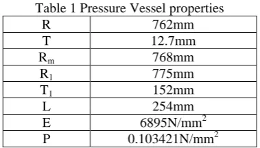
Table 1 Pressure Vessel properties
R 762mm
T 12.7mm
Rm 768mm
R1 775mm
T1 152mm
L 254mm
E 6895N/mm2
IJEDR1502020
International Journal of Engineering Development and Research (www.ijedr.org)105
Fig. 1 Pressure VesselB. Finite Element Model
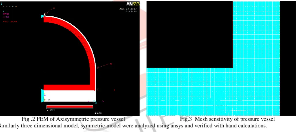
Taking the advantage of symmetry, a half model is prepared and analysis is done using ANSYS software.
Fig .2 FEM of Axisymmetric pressure vessel Fig.3 Mesh sensitivity of pressure vessel Similarly three dimensional model, symmetric model were analyzed using ansys and verified with hand calculations.
C. Modeling the contact behavior
Contact is changing-status nonlinearity. That is, the stiffness of the system depends on the contact status, whether parts are touching or separated. Physical contacting bodies do not interpenetrate. Therefore, the computational platform ANSYS establishes a relationship between the two surfaces to prevent them from passing through each other in the analysis. When the program prevents interpenetration, it said that it enforces contact compatibility Simulation offers several different contact algorithms to enforce compatibility at the contact interface. In the meshing generation, elements called “CONTACT” and “TARGET” are created on the interface of heads and shell, respectively. It internally adds constraint equations to “tie” the displacements between contacting surfaces. This approach is not penalty-based or Lagrange multiplier-based. It is a direct, efficient way of relating surfaces of contact regions which are bonded.
III. Results and Discussion
The axisymmetric model had by far the shortest run time with comparatively small computational error. Even the highly refined axisymmetric model ran in half the time of the fastest shell model. Not surprisingly, run time is proportional to the number of elements for a given element type. In axisymmetric models, when the mesh doubled, run time doubled and when mesh size quadrupled, the run time nearly quadrupled. Symmetric models offered an impressive improvement in run time. For the shell elements run time was reduced by roughly four times in each case.
IJEDR1502020
International Journal of Engineering Development and Research (www.ijedr.org)106
linear model. The solid model was the largest of the initial mesh models. The calculated error for all of the models was roughly the same. Only in one case did the error exceed seven percent. Even with the refined meshes, error did not necessarily improve.Since error between each element is fairly similar the choice of which to use will be dependent on the analysis being run. In cases where the required wall thickness is unknown, shell elements are an excellent choice since the wall thickness can be iterated by simply changing a constant without having to change the model geometry.When the wall thickness is known solid and axisymmetric models can provide greater data resolution. Shells only provide data at the wall edges. Solids allow for meshing inside the wall so the stress distribution can be studied through the wall thickness as well as on the outer surface. However, solid models have extremely high run times and consume large amounts of disk space. Axisymmetric models run considerably faster with no greater error. In fact, an axisymmetric model can be used with much greater resolution than a full solid model, yet will still run in less time and use less disk space.
Shell elements were found to have some unique problems that should be noted. When modeled using symmetric boundary conditions, a small number of elements can result in incorrect stresses along the boundary.
Contact Elements
For contact between the cylinder and heads three-dimensional surface to surface CONTAC172 elements were used. The CONTAC172 works by preventing the two surfaces from passing through each other. An element is generated between both nodes and given stiffness. If the stiffness is too low the outer node will pass through the inner node. However, if the stiffness is set too high the problem will not converge and no solution will be found. Thus, some experience in using these elements is useful
Axisymmetric Model
PLANE 82 ELEMENT
At junction “ O”
Stress(N/mm2) Inner surface Error (%)
Mean surface Error (%)
Outer surface Error (%)
Theoretical ANSYS Theoretical ANSYS Theoretical ANSYS
σt 4.732 4.637 2.007 4.730 4.513 4.58 4.638 4.393 5.077
σl 3.128 3.409 8.98 3.001 3.111 3.66 3.001 2.8111 6.33
σr -0.103 -0.103 0 -.0515 -0.058 9.92 0 0 0
At junction “ M” :
Stress(N/mm2) Inner surface Error (%)
Mean surface Error (%)
Outer surface Error (%)
Theoretical ANSYS Theoretical ANSYS Theoretical ANSYS
σt 6.122 6.479 5.83 5.001 5.683 8.79 4.289 4.883 9.2
σl 4.025 5.178 9.21 3.0789 3.066 .5 .225 .256 11.1
σr -.103 -0.106 1.9 0.05 .051 2 0 0 0
At junction “ L” :
Stress(N/mm2) Inner surface Error (%)
Mean surface Error (%)
Outer surface Error (%)
Theoretical ANSYS Theoretical ANSYS Theoretical ANSYS
σt 16.43 11.941 27.6 1.258 .579 32.2 -3.865 -4.29 8.5
σl 16.97 13.913 18.6 4.258 3.1 22.5 -10.74 -7.7 16.8
σr -.103 -.109 5.8 0.051 -0.049 3.9 0 0 0
3D MODEL:
SOLID 45 ELEMENT:
At junction “ O” :
Stress(N/mm2) Inner surface Error (%)
Mean surface Error (%)
Outer surface Error (%)
Theoretical ANSYS Theoretical ANSYS Theoretical ANSYS
IJEDR1502020
International Journal of Engineering Development and Research (www.ijedr.org)107
σl 3.128 3.43 7.6 3.001 3.077 2.53 3.128 2.722 8.9
σr -.103 -.103 0 0.051 .053 1.96 0 0 0
At junction “ M” :
Stress(N/mm2) Inner surface Error (%)
Mean surface Error (%)
Outer surface Error (%)
Theoretical ANSYS Theoretical ANSYS Theoretical ANSYS
σt 6.122 6.479 5.83 5.001 5.683 13.63 4.289 4.883 2.138
σl 4.025 5.878 6.83 3.0789 3.066 .418 .425 .256 9.76
σr -.103 -0.106 2.919 -0.05 -0.05 0 0 0 0
At junction “ L” :
Stress(N/mm2) Inner surface Error (%)
Mean surface Error (%)
Outer surface Error (%)
Theoretical ANSYS Theoretical ANSYS Theoretical ANSYS
σt 16.43 11.941 21.32 1.258 .979 12.3 -3.865 -4.26 10.99
σl 16.97 13.913 15.26 4.258 3.51 14.35 -10.74 -7.7 28.35
σr -.103 -.109 5.825 -.051 -0.049 3.9215 0 0 0
Similarly errors for symmetric model with shell elements are done .
IV. References
[1] David Heckman, 1998 ” Finite Element analysis of pressure vessel”, university of California, Davis.
[2] C.J. Dekker, H.J. Brink, 2000, “Nozzles on spheres with outward weld area under internal pressure analysed by FEM and thin shell theory”, International Journal ofPressure Vessels and Piping 77, 399-415.
[3] John F. Harvey, “Theory and Design of Modern Pressure Vessels”, Second Edition.
[4] Krishna P.singh,Alan I.soler,” Mechanical design of Heat exchanger and Pressure vessel components”, First edition 1984. [5] Liping Xue, G.E.O. Widera, Zhifu sang, 2007, “Burst pressure prediction of cylindrical shell intersection”, Transactions,
Smirt, Toronto.