IJEDR1403013
International Journal of Engineering Development and Research (www.ijedr.org)2968
Analysis of Pressure Safety Relief Valve using Finite
Element Analysis
1
Mr. M. V. Awati,
2Prof. S. G. Jadhav,
3Vinay G. Patil
1P.G.Student, 2Proffessor, 3Consultant
1Mechanical Department, Veermata Jijabai Technical Institute, Matunga 2
Vaftsy CAE, Pune
________________________________________________________________________________________________________ Abstract - Pressure safety relief valve is the key component in any system where pressure rising could be hazardous to safety of the workers as well as plant. Though electronically operated safety controls are there, but to take care of any malfunctioning in it, mechanically operated relief valve is necessary. In oil refinery sector, safety is of prime important. The clay canisters are used to refine the oil. Sometimes these canisters get clogged and pressure rising may take place. The key requirement of process is to relieve this pressure rise in no time. Conventional valves are unable to fulfill that requirement. This paper focuses on design and analysis of an emergency safety valve by Design by Analysis (DBA) approach. From the data given by the client, suitable valve is designed using FEA. The working environment is hazardous & explosive; hence ASME code is used to design. This valve is a onetime operating valve used as tertiary safety arrangement for critical applications.
Index Terms - Pressure safety valve, Non-linear FEA, Ansys workbench
________________________________________________________________________________________________________
I.INTRODUCTION Background Theory
In any process operating under pressure, safety is of prime importance. Pressure relief valves are provided to protect the equipment against critical pressure. It relieves the pressure exceeded than design pressure. Conventional safety valves are spring loaded safety valves in which pressure is acted on a plate working against the spring force. If the pressure exceeds than spring force, plate goes off the valve seat thus relieving the excess pressure. When pressure becomes normal, spring force pushes plate back to valve seat closing the valve. This process continues to work frequently when pressure change happens.
In fuel refining system, clay canisters get clogged due to surface coalescers or surfactants. Due to this pressure rise takes place which will be hazardous to the system. This paper focuses on design of an emergency shut off valve to handle above mentioned situation. It will open in no time relieving the excess pressure, thus avoiding the damage to the system. This valve will work as a backup arrangement with conventional arrangements.
Operation
When the pressure inside the equipment reaches at critical pressure, the plate is pushed against the CLIP ON‟s which are under preload of spring forces. CLIP ON‟s will break thus relieving the extra pressure through nozzle. Block dia. of safety valve is shown as follows in figure No. 1
Fig.1. Basic block diagram of pressure safety valve Objectives
IJEDR1403013
International Journal of Engineering Development and Research (www.ijedr.org)2969
3) Determining deformations and stresses at critical points.Table1 shows the input conditions of Valve.
Table.1 input condition and operating parameters
Sr.no Parameter Intensity
1 Pressure 0.14 Mpa
2 Valve inlet dia. 50mm
3 Nozzle opening dia. 36mm
4 Spring Nos. 3
5 Operating temp. 70 0 c
II.DESIGNPROCEDURE
Valve Body is designed by using ASME code. It consists of design of flat head, main shell, nozzle and upper and side flanges. As only atmospheric pressure is acting as external pressure, body is designed only for internal pressure. Suitable dimensions are assumed regarding body and nozzle. Non-linear finite analysis is used with suitable boundary conditions. Finally, optimization is done by no. of analysis to maintain maximum stress below the allowable limit.
A.Design of Valve Body
Valve body is designed by using ASME standard. Body is designed only for internal pressure as no external pressure is acting on valve. Material SA 516 gr.70 is selected for all the components except CLIP ON. AISI 309 stainless steel is selected for CLIP ON.
Design of Main Shell
According to ASME Section-VIII, Division-I, UG27, Required Thickness due to Internal Pressure [tr]: tr = P.R
S.E-0.6P
+ Corrosion Allowance tr=
0.1428
138.02
×28
×1-0.6×0.
3
1428
+3
tr =0.0301+3 tr =3.0301 mm
Thickness is modified as 8 mm for manufacturing purpose. All other dimensions are calculated by using ASME code and PV Elite software. Modeling is done in ANSYS workbench as shown in fig. 2
Figure.2 Valve body B. Design of plate
For design of plate, ASME code is used to determine the thickness of the plate Referring ASME section VIII, div-I, page no. 34.
CP
t
d
SE
Where,
C = factor considering the method of attachment (0.20 for fillet welding) d = diameter of the vessel.
IJEDR1403013
International Journal of Engineering Development and Research (www.ijedr.org)2970
E = Efficiency (summation of ligament and joint efficiency)For, 700 C i.e. SA 516 GR70 S = 138 Mpa
0.2*0.14 50
138*1 t
t=0.712 mm
This thickness is calculated only for internal pressure. But beside pressure, additional spring forces are going to act on plate. So it is modified as 4 mm.
C. Design of CLIP ON
CLIP ON‟ is facing shearing load as well as bending load. CLIP ON size is determined by DBA (Design by analysis) approach. It is taken as square cross section of 2 mm.
D. Design of Spring Parameters
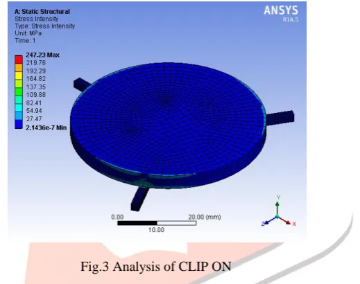
First, we calculated the force required to break the clip on at design pressure. No. of analysis are done in Ansys workbench to determine spring forces. Fig. 3 shows the analysis of CLIP ON.
Fig.3 Analysis of CLIP ON
Fixed support is provided at CLIP ON‟s while pressure of 0.14 Mpa is applied on plate. 3 patches 1200 apart are created to apply the spring forces. By trial and error method spring force is found out such that it will break the CLIP ON‟s.
It came as 134 N.
Spring deflection is assumed such that it will match suitably with body dimensions. It is assumed as 53.5 mm. Spring stiffness „K‟ becomes,
K=
Force
Deflection
K=13453.5 K=2.5 N/mm.
Other parameters of the spring are selected from a manufacturer. Details are given as follows Table 2. Spring parameters.
Type Helical tension spring
Stiffness 2.5 N/mm
Material ASTM A913-50
Outside Diameter 12.9 mm
Wire Diameter 2.8 mm
Spring Hook ASTM A441
Manufacturer Zhuji Angke
Free Length 42.5 mm
Maximum Deflection 82.5 mm (206.2 N)
III.NON-LINEAR ANALYSIS
IJEDR1403013
International Journal of Engineering Development and Research (www.ijedr.org)2971
1. Displacement is given to plate so that it will engage with the clip on and valve will be in closed position.2. Pressure of 0.14 Mpa is applied on plate. 3. Displacement is deactivated.
4. Displacement is given as 0 mm and contact between clip on and plate is killed by EKILL command.
5.
Pressure is applied on nozzle, shell, simulates the opening of the valve. Nozzle loads are also applied and stresses are calculated.A. Model
Valve body is modeled in ANSYS workbench 14.5.7. Parametric modeling is done so that at any stage change in one parameter will imply on whole assembly.
B. Meshing
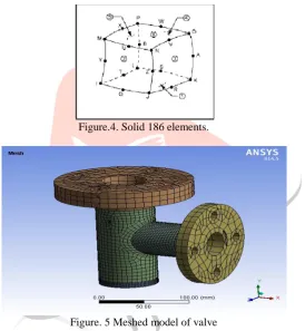
Meshing is done by using hex element with different sizes for different component. Fig. 5 shows Meshed model of valve Description of the element used for meshing
SOLID186 is a higher order 20 node hexahedron structural solid element. The element has any spatial orientation. The element input data includes the anisotropic material properties. The element supports plasticity, hyper elasticity, creep, stress stiffening, large deflection, and large strain capabilities. Fig. 4 shows 186 element.
Figure.4. Solid 186 elements.
Figure. 5 Meshed model of valve C. Boundary conditions
Faces of washer size are imprinted on upper flange and fixed support is applied there. Pressure of 0.14 Mpa is applied on plate and valve body at suitable step. Displacement of 53.5 mm is given to the plate for achieving initial position. Table 3 shows analysis details of valve.
Table 3 Analysis Details.
No. of steps 5
No. of sub steps 3 Non-linear effects ON
No. of nodes 134995
No. of elements 33065 Table 4 Nozzle Loadings
Fx (N) Fy (N) Fz (N) Mx (N-m) My (N-m) Mz (N-m)
5000 N 5000 N 6800 2300 2800 2300
IJEDR1403013
International Journal of Engineering Development and Research (www.ijedr.org)2972
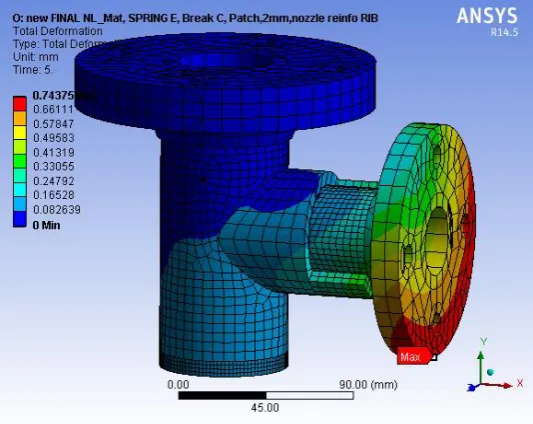
In first analysis total deformation is checked. It is within the limit. Stresses in the nozzle are exceeded beyond the allowable limit of the material yield stress. So additional reinforcement and rib attachment is provided to nozzle and optimization of attachment is done.Figure.6. Stresses in the nozzle before reinforcement
IJEDR1403013
International Journal of Engineering Development and Research (www.ijedr.org)2973
Figure 8 Total Deformation of Valve Body.E. Experimental Validation
Pressure safety valve is tested as per British Valve And Actuator Association (BVAA) standard. A criterion for validation is that valve should be open within 2 seconds. Following are the results obtained from the test.
Table 4 Experimental Results Readings
Trail no. Opening Pressure Opening Time
1 0.138 Mpa 1.5 sec
2 0.139 Mpa 1.4 sec
3 0.138 Mpa 1.6 sec
IV. CONCLUSION
The present work focuses on design of an emergency shut of valve. Non-linear analysis is carried out to obtain the results. Stresses and deformations are within permissible values. Additional reinforcement pad is attached to nozzle part to avoid failure. From the results we can say valve performs functionally well. Non linear analysis gives more accurate results regarding the stresses
REFERENCES
[1] Lloyd E Brownell & Edwin H Young, (1991), Process Equipment Design, Sixth Wiley Eastern Reprint, John Wiley & Sons, Inc., New York,
[2] Dennis R. Moss, (1997), Pressure Vessel Design Manual, Second Edition, Gulf Publishing Company, Houston, Texas. [3] ASME Section VIII Division 1, (2013), Alternative Rules for Construction of Pressure Vessels, Two Park Avenue, New
York.
[4] PV Elite 2014 Software Report and Help File.
[5] Dr. K.H. Jatkar, Sunil S. Dhanwe -“Finite Element Analysis of Gate Valve” International Journal of Engineering and Innovative Technology (IJEIT) Volume 2, Issue 10, April 2013,277-281
[6] D. Lal-“The Use of Finite Element Method for Stress Analysis of Compressor Valves” International compressor engineering conference, 1978.