EUROPEAN COMMISSION
Integrated Pollution Prevention and Control
Reference Document on
Best Available Techniques for the Manufacture of
Organic Fine Chemicals
August 2006
-20°C
-5°C 0°C
documents have been drafted):
Reference Document on Best Available Techniques . . . Code
Large Combustion Plants LCP
Mineral Oil and Gas Refineries REF
Production of Iron and Steel I&S
Ferrous Metals Processing Industry FMP
Non Ferrous Metals Industries NFM
Smitheries and Foundries Industry SF
Surface Treatment of Metals and Plastics STM
Cement and Lime Manufacturing Industries CL
Glass Manufacturing Industry GLS
Ceramic Manufacturing Industry CER
Large Volume Organic Chemical Industry LVOC
Manufacture of Organic Fine Chemicals OFC
Production of Polymers POL
Chlor – Alkali Manufacturing Industry CAK
Large Volume Inorganic Chemicals - Ammonia, Acids and Fertilisers Industries LVIC-AAF Large Volume Inorganic Chemicals - Solid and Others industry LVIC-S
Production of Speciality Inorganic Chemicals SIC
Common Waste Water and Waste Gas Treatment/Management Systems in the Chemical Sector CWW
Waste Treatments Industries WT
Waste Incineration WI
Management of Tailings and Waste-Rock in Mining Activities MTWR
Pulp and Paper Industry PP
Textiles Industry TXT
Tanning of Hides and Skins TAN
Slaughterhouses and Animals By-products Industries SA
Food, Drink and Milk Industries FDM
Intensive Rearing of Poultry and Pigs ILF
Surface Treatment Using Organic Solvents STS
Industrial Cooling Systems CV
Emissions from Storage ESB
Reference Document . . .
General Principles of Monitoring MON
Economics and Cross-Media Effects ECM
Energy Efficiency Techniques ENE
Electronic versions of draft and finalised documents are publically available and can be downloaded from http://eippcb.jrc.es.
EXECUTIVE SUMMARY
The BAT (Best Available Techniques) Reference Document (BREF) entitled “Best Available Techniques for the Manufacture of Organic Fine Chemicals” (OFC) reflects an information exchange carried out under Article 16(2) of Council Directive 96/61/EC (IPPC Directive). This executive summary describes the main findings, a summary of the principal BAT conclusions and the associated consumption and emission levels. It should be read in conjunction with the preface, which explains this document’s objectives; how it is intended to be used and legal terms. It can be read and understood as a standalone document but, as a summary, it does not present all the complexities of this full document. It is therefore not intended as a substitute for this full document as a tool in BAT decision making.
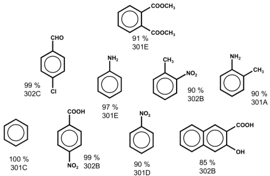
This document focuses on the batch manufacture of organic chemicals in multipurpose plants and addresses the manufacture of a wide range of organic chemicals although not all of them are explicitely named in ANNEX 1 of the Directive. The list is not conclusive but includes, e.g. dyes and pigments, plant health products and biocides, pharmaceutical products (chemical and biological processes), organic explosives, organic intermediates, specialised surfactants, flavours, fragrances, pheromones, plasticisers, vitamins, optical brighteners and flame-retardants. No specific threshold was established in drawing a borderline to large volume production. Therefore it is implied that an OFC production site may also include dedicated production lines for “larger” volume products with batch, semi-batch or continuous operation.
I. The sector and environmental issues
Organic fine chemical manufacturers produce a range of chemical substances, which are typically of a high added-value and produced in low volumes, mainly by batch processes in multipurpose plants. They are sold to companies, mostly other chemical companies, serving an immense range of end-user markets, on either a specification of purity or on their ability to deliver a particular effect. OFC manufacturers range in size from very small (<10 staff) to very large multinationals (>20000 staff), with typical manufacturing sites having between 150 and 250 staff.
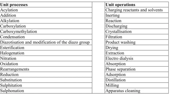
The chemistry of fine organic intermediates and products shows an enormous diversity. But in reality, the number of operations/processes used remains reasonably small. These include charging/discharging of reactants and solvents, inertisation, reactions, crystallisations, phase separations, filtrations, distillation, product washing. In many cases cooling, heating, or the application of vacuum or pressure is necessary. The unavoidable waste streams are treated in recovery/abatement systems or disposed of as waste.
The key environmental issues of the OFC sector are emissions of volatile organic compounds, waste waters with potential for high loads of non-degradable organic compounds, relatively large quantities of spent solvents and non-recyclable waste in high ratio. Given the diversity of the sector, the wide range of chemicals produced and the enormous variety of possibly emitted substances, this document does not provide a comprehensive overview of the releases from the OFC sector. No data on consumption of raw materials, etc. were available. However, emission data are presented from a broad range of example plants in the OFC sector.
II. Techniques to consider in the determination of BAT
The techniques to consider in the determination of BAT are grouped under the headings “Prevention and minimisation of environmental impact” (much related to the process design) and the “Management and treatment of waste streams”. The former includes strategies for the selection of the synthesis route, examples of alternative processes, equipment selection and
III. Best available techniques
The summary presented below does not include background statements and cross referencing which is found in the full text. Additionally, the full text contains BAT on environmental management. Where general BAT associated emission levels are given both in terms of concentration and mass flow, that which represents the greater amount in specific cases is intended as the BAT reference.
Prevention and minimisation
Integration of environmental considerations into process development
BAT is to provide an auditable trail for the integration of environmental, health and safety considerations into process development. BAT is to carry out a structured safety assessment for normal operation and to take into account effects due to deviations of the chemical process and deviations in the operation of the plant. BAT is to establish and implement procedures and technical measures to limit risks from the handling and storage of hazardous substances and to provide sufficient and adequate training for operators who handle hazardous substances. BAT is to design new plants in such a way that emissions are minimised. BAT is to design, build, operate and maintain facilities, where substances (usually liquids) which represent a potential risk of contamination of ground and groundwater are handled, in such a way that spill potential is minimised. Facilities have to be sealed, stable and sufficiently resistant against possible mechanical, thermal or chemical stress. BAT is to enable leakages to be quickly and reliably recognised. BAT is to provide sufficient retention volumes to safely retain spills and leaking substances, fire fighting water and contaminated surface water in order to enable treatment or disposal.
Enclosure of sources and airtightness of equipment
BAT is to contain and enclose sources and to close any openings in order to minimise uncontrolled emissions. Drying should be carried out by using closed circuits, including condensers for solvent recovery. BAT is to use recirculation of process vapours where purity requirements allow this. To minimise the volume flow, BAT is to close any unnecessary openings in order to prevent air being sucked to the gas collection system via the process equipment. BAT is to ensure the airtightness of process equipment, especially of vessels. BAT is to apply shock inertisation instead of continuous inertisation. Still, continuous inertisation has to be accepted due to safety requirements, e.g. where processes generate O2or where processes require further loading of material after inertisation.
Layout of distillation condensers
BAT is to minimise the exhaust gas volume flows from distillations by optimising the layout of the condenser.
Liquid addition to vessels, minimisation of peaks
BAT is to carry out liquid addition to vessels as bottom feed or with dip-leg, unless reaction chemistry and/or safety considerations make it impractical. In such cases, the addition of liquid as top feed with a pipe directed to the wall reduces splashing and hence, the organic load in the displaced gas. If both solids and an organic liquid are added to a vessel, BAT is to use solids as a blanket in circumstances where the density difference promotes the reduction of the organic load in the displaced gas, unless reaction chemistry and/or safety considerations make it impractical. BAT is to minimise the accumulation of peak loads and flows and related emission concentration peaks by, e.g. optimisation of the production matrix and application of smoothing filters.
Alternative techniques for product work-up
BAT is to avoid mother liquors with high salt content or to enable the work-up of mother liquors by the application of alternative separation techniques, e.g. membrane processes, solvent-based processes, reactive extraction, or to omit intermediate isolation. BAT is to apply countercurrent product washing where the production scale justifies the introduction of the technique.
Vacuum, cooling and cleaning
BAT is to apply water-free vacuum generation by using, e.g. dry running pumps, liquid ring pumps using solvents as the ring medium or closed cycle liquid ring pumps. However, where the applicability of these techniques is restricted, the use of steam injectors or water ring pumps is justified. For batch processes, BAT is to establish clear procedures for the determination of the desired end point of the reaction. BAT is to apply indirect cooling. However, indirect cooling is not applicable for processes which require the addition of water or ice to enable safe temperature control, temperature jumps or temperature shock. Direct cooling can also be required to control “run away” situations or where there are concerns about blocking heat-exchangers. BAT is to apply a pre-rinsing step prior to rinsing/cleaning of equipment to minimise organic loads in wash-waters. Where different materials are frequently transported in pipes, the use of pigging technology represents another option to reduce product losses within cleaning procedures.
Management and treatment of waste streams
Mass balances and analysis of waste streams
BAT is to establish mass balances for VOCs (including CHCs), TOC or COD, AOX or EOX (Extractable Organic Halogen) and heavy metals on a yearly basis. BAT is to carry out a detailed waste stream analysis in order to identify the origin of the waste stream and a basic data set to enable management and suitable treatment of exhaust gases, waste water streams and solid residues. BAT is to assess at least the parameters given in Table I for waste water streams, unless the parameter can be seen as irrelevant from a scientific point of view.
Parameter Volume per batch
Batches per year Volume per day Volume per year COD or TOC BOD5
pH
Bioeliminability
Biological inhibition, including nitrification
Standard AOX CHCs Solvents Heavy metals Total N Total P Chloride Bromide SO4 2-Residual toxicity Where it is expected
Table I: Parameters for the assessment of waste water streams Monitoring of emissions to air
Emission profiles should be recorded instead of levels derived from short sampling periods. Emission data should be related to the operations responsible. For emissions to air, BAT is to monitor the emission profile which reflects the operational mode of the production process. In the case of a non-oxidative abatement/recovery system, BAT is to apply a continuous monitoring system (e.g. Flame Ionisation Detector, FID), where exhaust gases from various
Individual volume flows
BAT is to assess the individual exhaust gas volume flows from process equipment to recovery/abatement systems.
Re-use of solvents
BAT is to re-use solvents as far as purity requirements allow. This is carried out by using the solvent from previous batches of a production campaign for future batches, collecting spent solvents for on-site or off-site purification and re-use, or collecting spent solvents for on-site or off-site utilisation of the calorific value.
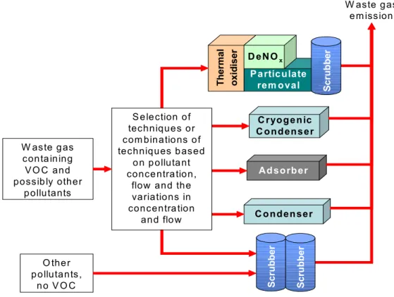
Selection of VOC treatment techniques
One or a combination of techniques can be applied as a recovery/abatement system for a whole site, an individual production building, or an individual process. This depends on the particular situation and affects the number of point sources. BAT is to select VOC recovery and abatement techniques according to the flow scheme in Figure I.
Non-oxidative VOC recovery or abatement: achievable emission levels
Where non-oxidative VOC recovery or abatement techniques are applied, BAT is to reduce emissions to the levels given in Table II.
Thermal oxidation/incineration or catalytic oxidation: achievable emission levels
Where thermal oxidation/incineration or catalytic oxidation are applied, BAT is to reduce VOC emissions to the levels given in Table III.
Recovery/abatement of NOX
For thermal oxidation/incineration or catalytic oxidation, BAT is to achieve the NOXemission levels given in Table IV and, where necessary, to apply a DeNOXsystem (e.g. SCR or SNCR) or two stage combustion to achieve such levels. For exhaust gases from chemical production processes, BAT is to achieve the NOXemission levels given in Table IV and, where necessary to apply treatment techniques such as scrubbing or scrubber cascades with scrubber media such as H2O and/or H2O2 to achieve such levels. Where NOXfrom chemical processes is absorbed from strong NOXstreams (about 1000 ppm and higher) a 55 % HNO3can be obtained for on-site or off-on-site re-use. Often, exhaust gases containing NOX from chemical processes also contain VOCs and can be treated in a thermal oxidiser/incinerator, e.g. equipped with a DeNOX unit or built as a two stage combustion (where already available on-site).
Recovery/abatement of HCl, Cl2, HBr, NH3, SOxand cyanides
HCl can be efficiently recovered from exhaust gases with high HCl concentrations, if the production volume justifies the investment costs for the required equipment. Where HCl recovery is not preceded by VOC removal, potential organic contaminants (AOX) have to be considered in the recovered HCl. BAT is to achieve the emission levels given in Table VI and, where necessary, to apply one or more scrubbers using suitable scrubbing media.
Removal of particulates
Particulates are removed from various exhaust gases. The choice of recovery/abatement systems depends strongly on the particulate properties. BAT is to achieve particulate emission levels of 0.05 – 5 mg/m3or 0.001 – 0.1 kg/hour and, where necessary, to apply techniques such as bag filters, fabric filters, cyclones, scrubbing, or wet electrostatic precipitation (WESP) in order to achieve such levels.
VOCs in exhaust gases Levels from Table II achievable ? Connect exhaust gas
stream to one or more condensers for recovery,
using temperatures suitable for the VOCs
End
Levels from Table II
achievable ?
Assess the application of one or a combination of
non-oxidative treatment techniques
Assess the optimisation by:
• increasing the existing treatment capacity • increasing treatment efficiency
• adding techniques with higher efficiency
Levels from Table II
achievable ?
One or more criteria for thermal or catalytic
oxidation fulfilled ? (Table V)
End
Apply thermal or catalytic oxidation and achieve
levels from Table III or apply another technique
or combination of techniques achieving at least an equivalent emission level End Yes No Yes Yes Yes No No No Apply one or a combination of non-oxidative treatment techniques Apply the optimised configuration
Figure I: BAT for the selection of VOC recovery/abatement techniques
Parameter Average emission level from point sources* Total organic C 0.1 kg C/hour or 20 mg C/m3** * The averaging time relates to the emission profile, the levels relate to dry gas and Nm3
Thermal oxidation/incineration
or catalytic oxidation Average mass flow kg C/hour Average concentration mg C/m3
Total organic C <0.05 or <5
The averaging time relates to the emission profile, levels relate to dry gas and Nm3
Table III: BAT associated emission levels for total organic C for thermal oxidation/incineration or catalytic oxidation
Source Average
kg/hour*
Average
mg/m3* Comment
Chemical production processes, e.g. nitration, recovery of spent
acids 0.03 – 1.7 7 – 220
**
The lower end of the range relates to low inputs to the scrubbing system and scrubbing with H2O. With high input
levels, the lower end of the range is not achievable even with H2O2as the scrubbing
medium Thermal oxidation/incineration,
catalytic oxidation 0.1 – 0.3 13 – 50*** Thermal oxidation/incineration,
catalytic oxidation, input of nitrogenous organic compounds
or
25 – 150*** Lower range with SCR, upper range with SNCR
* ** ***
NOXexpressed as NO2, the averaging time relates to the emission profile
Levels relate to dry gas and Nm3
Levels relate to dry gas and Nm3
Table IV: BAT associated NOxemission levels Selection criteria
a The exhaust gas contains very toxic, carcinogenic or cmr category 1 or 2 substances, or b autothermal operation is possible in normal operation, or
c overall reduction of primary energy consumption is possible in the installation (e.g. secondary heat option) Table V: Selection criteria for catalytic and thermal oxidation/incineration
Parameter Concentration Mass flow
HCl 0.2 – 7.5 mg/m3 0.001 – 0.08 kg/hour Cl2 0.1 – 1 mg/m3 HBr <1 mg/m3 NH3 0.1 – 10 mg/m3 0.001 – 0.1 kg/hour NH3from SCR or SNCR <2 mg/m3 <0.02 kg/hour SOx 1 – 15 mg/m3 0.001 – 0.1 kg/hour Cyanides as HCN 1 mg/m3 or 3 g/hour Table VI: BAT associated emission levels for HCl, Cl2, HBr, NH3, SOxand cyanides
Typical waste water streams for segregation and selective pretreatment
BAT is to segregate and pretreat or dispose of mother liquors from halogenations and sulphochlorinations. BAT is to pretreat waste water streams containing biologically active substances at levels which could pose a risk either to a subsequent waste water treatment or to the receiving environment after discharge. BAT is to segregate and collect separately spent acids, e.g. from sulphonations or nitrations for on-site or off-site recovery or to apply BAT about pretreatment of refractory organic loadings.
Pretreatment of waste water streams with refractory organic loadings
BAT is to segregate and pretreat waste water streams containing relevant refractory organic loadings according to this classification: Refractory organic loading is not relevant if the waste water stream shows a bioeliminability of greater than about 80 - 90 %. In cases with lower bioeliminability, the refractory organic loading is not relevant if it is lower than the range of about 7.5 - 40 kg TOC per batch or per day. For the segregated waste water streams, BAT is to achieve overall COD elimination rates for the combination of pretreatment and biological treatment of >95 %.
Recovery of solvents from waste water streams
BAT is to recover solvents from waste water streams for on-site or off-site re-use, where the costs for biological treatment and purchase of fresh solvents are higher than the costs for recovery and purification. This is carried out by using techniques such as stripping, distillation/rectification, extraction or combinations of such techniques. BAT is to recover solvents from waste water streams in order to use the calorific value if the energy balance shows that overall natural fuel can be substituted.
Removal of halogenated compounds from waste water streams
BAT is to remove purgeable CHCs from waste water streams, e.g. by stripping, rectification or extraction and to achieve levels given in Table VII. BAT is to pretreat waste water streams with significant AOX loads and to achieve the AOX levels given in Table VII in the inlet to the on-site biological Waste Water Treatment Plant (WWTP) or in the inlet to the municipal sewerage system.
Removal of heavy metals from waste water streams
BAT is to pretreat waste water streams containing significant levels of heavy metals or heavy metal compounds from processes where they are used deliberately and to achieve the heavy metal concentrations given in Table VII in the inlet to the on-site biological WWTP or in the inlet to the municipal sewerage system. If equivalent removal levels can be demonstrated in comparison with the combination of pretreatment and biological waste water treatment, heavy metals can be eliminated from the total effluent using only the biological waste water treatment process, provided that the biological treatment is carried out on-site and the treatment sludge is incinerated.
Parameter average Yearly Unit Comment
AOX 0.5 - 8.5
The upper range relates to cases where halogenated compounds are processed in numerous processes and the corresponding waste water streams are pretreated and/or where the AOX is very bioeliminable
Purgeable
CHCs <0.1 Alternatively achieve a sum concentration of <1 mg/l in the outlet from pretreatment
Cu 0.03 - 0.4
Cr 0.04 - 0.3
Ni 0.03 - 0.3
mg/l
The upper ranges result from the deliberate use of heavy metals or heavy metal compounds in numerous processes and the pretreatment of waste water streams from such use
Free cyanides
BAT is to recondition waste water streams containing free cyanides in order to substitute raw materials where technically possible. BAT is to pretreat waste water streams containing significant loads of cyanides and to achieve a cyanide level of 1 mg/l or lower in the treated waste water stream or to enable safe degradation in a biological WWTP.
Biological waste water treatment
BAT is to treat effluents containing a relevant organic load, such as waste water streams from production processes, rinsing and cleaning water, in a biological WWTP. BAT is to ensure that the elimination in a joint waste water treatment is overall not poorer than in the case of on-site treatment. For biological waste water treatment, COD elimination rates of 93 – 97 % are typically achievable as a yearly average. It is important that a COD elimination rate cannot be understood as a standalone parameter, but is influenced by the production spectrum (e.g production of dyes/pigments, optical brighteners, aromatic intermediates which create refractory loadings in most of the waste water streams on a site), the degree of solvent removal and the degree of pretreatment of refractory organic loadings. Depending on the individual situation, retrofitting of the biological WWTP is required in order to adjust, e.g. treatment capacity or buffer volume or the application of a nitrification/denitrification or a chemical/mechanical stage. BAT is to take full advantage of the biological degradation potential of the total effluent and to achieve BOD elimination rates above 99 % and yearly average BOD emission levels of 1 - 18 mg/l. The levels relate to the effluent after biological treatment without dilution, e.g. by mixing with cooling water. BAT is to achieve the emission levels given in Table VIII.
Monitoring of the total effluent
BAT is to regularly monitor the total effluent to and from the biological WWTP. BAT is to carry out regular biomonitoring of the total effluent after the biological WWTP where substances with ecotoxicological potential are handled or produced with or without intention. Where residual toxicity is identified as a concern (e.g. where fluctuations of the performance of the biological WWTP can be related to critical production campaigns), BAT is to apply online toxicity monitoring in combination with online TOC measurement.
Yearly averages*
Parameter Level Unit Comment
COD 12 - 250
Total P 0.2 - 1.5 The upper range results from the production of mainly compounds containing phosphorus Inorganic N 2 - 20 The upper range results from production of mainly organic compounds containing nitrogen or from, e.g.
fermentation processes AOX 0.1 - 1.7
The upper range results from numerous AOX relevant productions and pretreatment of waste water streams with significant AOX loads
Cu 0.007 - 0.1 Cr 0.004 - 0.05 Ni 0.01 - 0.05
Zn – 0.1
The upper ranges result from the deliberate use of heavy metals or heavy metal compounds in numerous processes and the pretreatment of waste water streams from such use Suspended solids 10 - 20 mg/l LIDF 1 - 2 LIDD 2 - 4 LIDA 1 - 8 LIDL 3 - 16 LIDEU 1.5 Dilution factor
Toxicity is also expressed as aquatic toxicity (EC50 levels)
*The levels relate to the effluent after biological treatment without dilution, e.g. by mixing with
cooling water
IV. Concluding remarks
The information exchange on Best Available Techniques for the Manufacture of Organic Fine Chemicals was carried out from 2003 to 2005. The information exchange process was successful and a high degree of consensus was reached during and following the final meeting of the Technical Working Group. No split views were recorded. However, it has to be noted that increasing confidentiality concerns represented a considerable obstacle throughout the work. The EC is launching and supporting, through its RTD programmes, a series of projects dealing with clean technologies, emerging effluent treatment and recycling technologies and management strategies. Potentially these projects could provide a useful contribution to future BREF reviews. Readers are therefore invited to inform the EIPPCB of any research results which are relevant to the scope of this document (see also the Preface of this document).
PREFACE
1. Status of this document
Unless otherwise stated, references to “the Directive” in this document means the Council Directive 96/61/EC on integrated pollution prevention and control. As the Directive applies without prejudice to Community provisions on health and safety at the workplace, so does this document.
This document forms part of a series presenting the results of an exchange of information between EU Member States and industries concerned on best available technique (BAT), associated monitoring, and developments in them. It is published by the European Commission pursuant to Article 16(2) of the Directive, and must therefore be taken into account in accordance with Annex IV of the Directive when determining “best available techniques”. 2. Relevant legal obligations of the IPPC Directive and the definition of BAT
In order to help the reader understand the legal context in which this document has been drafted, some of the most relevant provisions of the IPPC Directive, including the definition of the term “best available techniques”, are described in this preface. This description is inevitably incomplete and is given for information only. It has no legal value and does not in any way alter or prejudice the actual provisions of the Directive.
The purpose of the Directive is to achieve integrated prevention and control of pollution arising from the activities listed in its Annex I, leading to a high level of protection of the environment as a whole. The legal basis of the Directive relates to environmental protection. Its implementation should also take account of other Community objectives such as the competitiveness of the Community’s industry thereby contributing to sustainable development. More specifically, it provides for a permitting system for certain categories of industrial installations requiring both operators and regulators to take an integrated, overall look at the polluting and consuming potential of the installation. The overall aim of such an integrated approach must be to improve the management and control of industrial processes so as to ensure a high level of protection for the environment as a whole. Central to this approach is the general principle given in Article 3 that operators should take all appropriate preventative measures against pollution, in particular through the application of best available techniques enabling them to improve their environmental performance.
The term “best available techniques” is defined in Article 2(11) of the Directive as “the most effective and advanced stage in the development of activities and their methods of operation which indicate the practical suitability of particular techniques for providing in principle the basis for emission limit values designed to prevent and, where that is not practicable, generally to reduce emissions and the impact on the environment as a whole.” Article 2(11) goes on to clarify further this definition as follows:
“techniques” includes both the technology used and the way in which the installation is designed, built, maintained, operated and decommissioned;
“available” techniques are those developed on a scale which allows implementation in the relevant industrial sector, under economically and technically viable conditions, taking into consideration the costs and advantages, whether or not the techniques are used or produced inside the Member State in question, as long as they are reasonably accessible to the operator; “best” means most effective in achieving a high general level of protection of the environment
Furthermore, Annex IV of the Directive contains a list of “considerations to be taken into account generally or in specific cases when determining best available techniques... bearing in mind the likely costs and benefits of a measure and the principles of precaution and prevention”. These considerations include the information published by the Commission pursuant to Article 16(2).
Competent authorities responsible for issuing permits are required to take account of the general principles set out in Article 3 when determining the conditions of the permit. These conditions must include emission limit values, supplemented or replaced where appropriate by equivalent parameters or technical measures. According to Article 9(4) of the Directive, these emission limit values, equivalent parameters and technical measures must, without prejudice to compliance with environmental quality standards, be based on the best available techniques, without prescribing the use of any technique or specific technology, but taking into account the technical characteristics of the installation concerned, its geographical location and the local environmental conditions. In all circumstances, the conditions of the permit must include provisions on the minimisation of long-distance or transboundary pollution and must ensure a high level of protection for the environment as a whole.
Member States have the obligation, according to Article 11 of the Directive, to ensure that competent authorities follow or are informed of developments in best available techniques. 3. Objective of this Document
Article 16(2) of the Directive requires the Commission to organise “an exchange of information between Member States and the industries concerned on best available techniques, associated monitoring and developments in them”, and to publish the results of the exchange.
The purpose of the information exchange is given in recital 25 of the Directive, which states that “the development and exchange of information at Community level about best available techniques will help to redress the technological imbalances in the Community, will promote the worldwide dissemination of limit values and techniques used in the Community and will help the Member States in the efficient implementation of this Directive.”
The Commission (Environment DG) established an information exchange forum (IEF) to assist the work under Article 16(2) and a number of technical working groups have been established under the umbrella of the IEF. Both IEF and the technical working groups include representation from Member States and industry as required in Article 16(2).
The aim of this series of documents is to reflect accurately the exchange of information which has taken place as required by Article 16(2) and to provide reference information for the permitting authority to take into account when determining permit conditions. By providing relevant information concerning best available techniques, these documents should act as valuable tools to drive environmental performance.
4. Information Sources
This document represents a summary of information collected from a number of sources, including in particular the expertise of the groups established to assist the Commission in its work, and verified by the Commission services. All contributions are gratefully acknowledged. 5. How to understand and use this document
The information provided in this document is intended to be used as an input to the determination of BAT in specific cases. When determining BAT and setting BAT-based permit conditions, account should always be taken of the overall goal to achieve a high level of protection for the environment as a whole.
The rest of this section describes the type of information that is provided in each section of the document.
Chapters 1 and 2 provide general information on the industrial sector concerned and on the industrial processes used within the sector. Chapter 3 provides data and information concerning current emission and consumption levels reflecting the situation in existing installations at the time of writing.
Chapter 4 describes in more detail the emission reduction and other techniques that are considered to be most relevant for determining BAT and BAT-based permit conditions. This information includes the consumption and emission levels considered achievable by using the technique, some idea of the costs and the cross-media issues associated with the technique, and the extent to which the technique is applicable to the range of installations requiring IPPC permits, for example new, existing, large or small installations. Techniques that are generally seen as obsolete are not included.
Chapter 5 presents the techniques and the emission and consumption levels that are considered to be compatible with BAT in a general sense. The purpose is thus to provide general indications regarding the emission and consumption levels that can be considered as an appropriate reference point to assist in the determination of BAT-based permit conditions or for the establishment of general binding rules under Article 9(8). It should be stressed, however, that this document does not propose emission limit values. The determination of appropriate permit conditions will involve taking account of local, site-specific factors such as the technical characteristics of the installation concerned, its geographical location and the local environmental conditions. In the case of existing installations, the economic and technical viability of upgrading them also needs to be taken into account. Even the single objective of ensuring a high level of protection for the environment as a whole will often involve making trade-off judgements between different types of environmental impact, and these judgements will often be influenced by local considerations.
Although an attempt is made to address some of these issues, it is not possible for them to be considered fully in this document. The techniques and levels presented in Chapter 5 will therefore not necessarily be appropriate for all installations. On the other hand, the obligation to ensure a high level of environmental protection including the minimisation of long-distance or transboundary pollution implies that permit conditions cannot be set on the basis of purely local considerations. It is therefore of the utmost importance that the information contained in this document is fully taken into account by permitting authorities.
Reference plants
Apart from references to literature, this document refers frequently to reference plants. Due to widely spread confidentiality concerns, all reference plants are named with an alias (example: *199D,O,X*) where the number can be used to identify the reference plant throughout this document and the following letters indicate the production spectrum as follows:
A API
B Biocides and/or plant health products D Dyes and/or pigments
E Explosives
F Flavours and/or fragrances I Intermediates
L Large integrated multiproduct site O Optical brighteners
6. Future review and update
Since the best available techniques change over time, this document will be reviewed and updated as appropriate. All comments and suggestions should be made to the European IPPC Bureau at the Institute for Prospective Technological Studies at the following address:
Edificio Expo, c/ Inca Garcilaso, s/n, E-41092 Sevilla, Spain Telephone: +34 95 4488 284
Fax: +34 95 4488 426
e-mail: [email protected]
Best Available Techniques Reference Document for
the Manufacture of Organic Fine Chemicals
EXECUTIVE SUMMARY...I PREFACE...XI SCOPE ... XXVII 1 GENERAL INFORMATION... 1 1.1 The sector ... 1 1.2 Environmental issues ... 4 1.3 Some products ... 5
1.3.1 Organic dyes and pigments ... 5
1.3.1.1 Overview ...5
1.3.1.2 Pigments ...6
1.3.1.3 Economics ...7
1.3.2 Active pharmaceutical ingredients (APIs)... 8
1.3.2.1 Overview ...8
1.3.2.2 Legal requirements and process modifications ...8
1.3.2.3 Economics ...9
1.3.3 Vitamins ... 9
1.3.4 Biocides and plant health products... 10
1.3.4.1 Overview ...10
1.3.4.2 Process modifications in manufacturing crop protection agents ...11
1.3.4.3 Economics of crop protection ...12
1.3.5 Fragrances and flavours... 13
1.3.6 Optical brighteners ... 14
1.3.7 Flame-retardants... 15
1.3.8 Plasticisers... 16
1.3.9 Explosives ... 17
2 APPLIED PROCESSES AND TECHNIQUES ... 19
2.1 Conception: unit processes and operations ... 19
2.1.1 Intermediates ... 20
2.1.2 Isomers and by-products ... 21
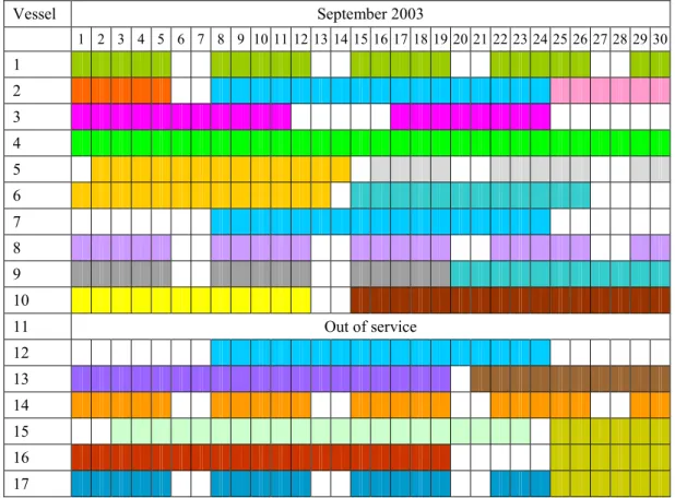
2.2 Multipurpose plants ... 22
2.3 Equipment and unit operations ... 24
2.3.1 Reactors... 24
2.3.1.1 Liquid addition to reactors ...25
2.3.2 Equipment and operations for product work-up... 25
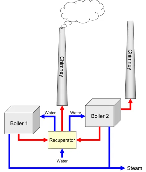
2.3.2.1 Drying...25 2.3.2.2 Liquid-solid separation ...26 2.3.2.3 Distillation ...26 2.3.2.4 Liquid-liquid extraction ...26 2.3.3 Cooling... 27 2.3.4 Cleaning ... 27 2.3.5 Energy supply... 28 2.3.6 Vacuum systems... 29
2.3.7 Recovery/abatement of exhaust gases ... 30
2.3.8 Recovery/abatement applied to waste water streams ... 31
2.3.9 Groundwater protection and fire fighting water ... 32
2.3.10 Solvent recovery ... 33
2.4 Site management and monitoring ... 34
2.4.1 Emission inventories and monitoring ... 34
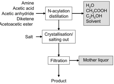
2.5.1 N-acylation...40
2.5.2 Alkylation with alkyl halides ...41
2.5.3 Condensation ...42
2.5.4 Diazotisation and azo coupling ...43
2.5.5 Esterification...45
2.5.6 Halogenation...48
2.5.7 Nitration...51
2.5.8 Manufacture of nitrated alcohols ...53
2.5.9 Oxidation with inorganic agents ...54
2.5.10 Phosgenation ...55
2.5.11 Reduction of aromatic nitro compounds...56
2.5.11.1 Catalytic reduction with hydrogen...56
2.5.11.2 Reduction with iron ...57
2.5.11.3 Alkali sulphide reduction...58
2.5.11.4 Product work-up ...58
2.5.12 Sulphonation...59
2.5.13 Sulphonation with SO3...61
2.5.14 Sulphochlorination with chlorosulphonic acid ...63
2.5.15 Wittig reaction ...65
2.5.16 Processes involving heavy metals ...66
2.6 Fermentation ...68
2.6.1 Operations...68
2.6.2 Environmental issues ...70
2.7 Associated activities...72
2.7.1 Formulation...72
2.7.2 Extraction from natural materials ...73
3 CURRENT EMISSION AND CONSUMPTION LEVELS ...75
3.1 Emissions to air ...75
3.1.1 VOC emissions: overview ...75
3.1.2 Concentration values and DeNOXefficiencies ...76
3.1.3 Mass flows ...79
3.2 Waste water...82
3.2.1 Reported COD and BOD5emissions and elimination efficiencies ...82
3.2.2 Reported emissions for inorganic parameters and related elimination efficiencies ...85
3.2.3 Reported emission values for AOX and toxicities ...87
3.3 Waste...88
4 TECHNIQUES TO CONSIDER IN THE DETERMINATION OF BAT...89
4.1 Prevention of environmental impact ...90
4.1.1 Green chemistry...90
4.1.2 Integration of EHS considerations into process development...92
4.1.3 Example for a solvent selection guide ...94
4.1.4 Examples for alternative synthesis and reaction conditions...98
4.1.4.1 Sulphonation with SO3in gas-liquid reaction...98
4.1.4.2 Dry acetylation of a naphthylamine sulphonic acid ...99
4.1.4.3 Recycling instead of treatment/disposal of TPPO...100
4.1.4.4 Enzymatic processes versus chemical processes...103
4.1.4.5 Catalytic reduction...105
4.1.4.6 Microstructured reactor systems ...106
4.1.4.7 Reactions in ionic liquids...108
4.1.4.8 Cryogenic reactions ...110
4.1.4.9 Reactions in supercritical CO2...111
4.1.4.10 Substitution of butyllithium ...113
4.1.5 Extraction from natural products ...114
4.1.5.1 Extraction from natural products with liquid CO2...114
4.1.5.2 Countercurrent band extraction...115
4.1.5.3 Enabling the re-use of residual plant material from extraction ...116
4.1.6 Safety assessment ...117
4.1.6.1 Physico-chemical safety assessment of chemical reactions ...117
4.1.6.2 About the prevention of runaway reactions ...122
4.1.6.3 Useful links and further information...123
4.2 Minimisation of environmental impacts...124
4.2.2 Site assessment before process launch ... 126
4.2.3 Precautions in the production of herbicides ... 128
4.2.4 Improvement of “letter acid” production... 130
4.2.5 Water-free vacuum generation ... 132
4.2.6 Liquid ring vacuum pumps using solvents as the ring medium... 134
4.2.7 Closed cycle liquid ring vacuum pumps... 136
4.2.8 Pigging systems... 137
4.2.9 Indirect cooling ... 140
4.2.10 Pinch methodology ... 141
4.2.11 Energetically coupled distillation... 144
4.2.12 Optimised equipment cleaning (1) ... 146
4.2.13 Optimised equipment cleaning (2) ... 147
4.2.14 Minimisation of VOC emissions (1) ... 148
4.2.15 Minimisation of VOC emissions (2) ... 149
4.2.16 Airtightness of vessels ... 151
4.2.17 Shock inertisation of vessels ... 152
4.2.18 Liquid addition into vessels ... 154
4.2.19 Solid-liquid separation in closed systems ... 155
4.2.20 Minimisation of exhaust gas volume flows from distillation... 156
4.2.21 Segregation of waste water streams ... 158
4.2.22 Countercurrent product washing ... 160
4.2.23 Example for reaction control: azo coupling ... 162
4.2.24 Avoidance of mother liquors with high salt contents... 163
4.2.25 Reactive extraction... 165
4.2.26 Use of pressure permeation in dye manufacture ... 166
4.2.27 Ground protection ... 168
4.2.28 Retention of fire fighting and contaminated surface water ... 170
4.2.29 Example: training of phosgenation operators... 171
4.2.30 Example: Handling of phosgene ... 173
4.3 Management and treatment of waste streams ... 175
4.3.1 Balances and monitoring ... 176
4.3.1.1 Process waste stream analysis...176
4.3.1.2 Analysis of waste water streams ...179
4.3.1.3 Refractory organic loading: Zahn-Wellens test...181
4.3.1.4 Mass balances for solvents (VOC), highly hazardous substances and heavy metals ...183
4.3.1.5 TOC balance for waste water streams...185
4.3.1.6 AOX balance for waste water streams ...187
4.3.1.7 Monitoring of exhaust gas volume flows from processes ...189
4.3.1.8 Monitoring of waste gas emissions...190
4.3.2 Waste streams from unit processes... 192
4.3.2.1 Waste streams from N-acylation...192
4.3.2.2 Waste streams from alkylations with alkyl halides ...194
4.3.2.3 Waste streams from condensations ...196
4.3.2.4 Waste streams from diazotisation and azo coupling ...198
4.3.2.5 Waste streams from halogenation ...203
4.3.2.6 Waste streams from nitrations...206
4.3.2.7 Waste streams from the reduction of aromatic nitro compounds ...209
4.3.2.8 Waste streams from sulphonation ...212
4.3.2.9 Waste streams from sulphonation with SO3...216
4.3.2.10 Waste streams from sulphochlorination...218
4.3.2.11 Waste water streams from fermentation...220
4.3.3 Recovery of aromatic solvents and lower alcohols ... 222
4.3.4 Re-use and recycling of solvents and by-products ... 226
4.3.5 Treatment of exhaust gases ... 227
4.3.5.1 Recovery of NOXfrom exhaust gases...227
4.3.5.2 Recovery of HCl from exhaust gases...229
4.3.5.3 Scrubbing of HCl from exhaust gases and related emission levels ...232
4.3.5.4 Recovery of bromine and HBr from exhaust gases...234
4.3.5.5 Absorption of excess chlorine from exhaust gases...236
4.3.5.6 Condensation of VOCs from reactors and distillations...238
4.3.5.14 Non-thermal exhaust gas treatments ...256
4.3.5.15 Induction of non-thermal plasma and catalytic oxidation of VOCs...258
4.3.5.16 Minimising emission concentration peaks ...259
4.3.5.17 Management of a modular exhaust gas treatment setup...261
4.3.5.18 Selection of a VOC treatment and emission levels ...264
4.3.5.19 NOX: recovery, abatement and emission levels ...268
4.3.5.20 Scrubbing of NH3from exhaust gases and related emission levels...272
4.3.5.21 Scrubbing of SOXfrom exhaust gases and related emission levels...274
4.3.5.22 Particulate removal from exhaust gases...276
4.3.6 Destruction of free cyanides ...277
4.3.6.1 Destruction of free cyanides with NaOCl ...277
4.3.6.2 Destruction of free cyanides with H2O2...279
4.3.7 Management and treatment of waste water streams...281
4.3.7.1 Pretreatment of waste water streams by separation...281
4.3.7.2 Pretreatment of waste water streams by oxidation...283
4.3.7.3 Pretreatment options for waste water streams on an OFC plant...285
4.3.7.4 Joint pretreatment of waste water streams by wet oxidation with O2...287
4.3.7.5 Pretreatment on production sites for biocides/plant health products...291
4.3.7.6 Management of waste water streams (1)...293
4.3.7.7 Management of waste water streams (2)...295
4.3.7.8 Management of waste water streams (3)...297
4.3.7.9 Waste water streams for obligatory pretreatment or disposal ...298
4.3.7.10 Refractory organic loadings (1) ...300
4.3.7.11 Refractory organic loadings (2) ...302
4.3.7.12 Refractory organic loadings (3) ...303
4.3.7.13 Refractory organic loadings (4) ...304
4.3.7.14 AOX elimination from waste water streams (1) ...306
4.3.7.15 AOX elimination from waste water streams (2) ...309
4.3.7.16 AOX elimination from waste water streams (3) ...311
4.3.7.17 AOX: removal of iodine compounds from waste water streams by means of nanofiltration....313
4.3.7.18 Removal of CHCs and solvents from waste water streams...314
4.3.7.19 Removal of CHCs from waste water streams (2)...316
4.3.7.20 Removal of CHCs from waste water streams (3)...318
4.3.7.21 Removal of nickel from process waters ...319
4.3.7.22 Heavy metals removal from waste water streams ...321
4.3.7.23 Recovery of iodine from waste water streams ...324
4.3.7.24 Disposal of waste water streams containing high P loads...325
4.3.8 Treatment of the total effluent and related emission levels...326
4.3.8.1 Achievable values for heavy metals in the total effluent ...326
4.3.8.2 Pretreatment of the total effluent by chemical oxidation with H2O2...327
4.3.8.3 On-site instead of off-site biological WWTP...329
4.3.8.4 Joint treatment with municipal waste water...330
4.3.8.5 Proving the efficiency of off-site waste water treatment...332
4.3.8.6 Treatment of the total effluent ...333
4.3.8.7 Protection and performance of biological WWTPs (1)...335
4.3.8.8 Protection and performance of biological WWTPs (2)...337
4.3.8.9 COD elimination rates: waste water streams ...339
4.3.8.10 Understanding COD emission levels and elimination rates ...340
4.3.8.11 BOD elimination rates and emission levels ...344
4.3.8.12 AOX elimination rates and emission levels ...346
4.3.8.13 LID emission levels ...348
4.3.8.14 Nitrogen emission levels...350
4.3.8.15 Elimination of inorganic nitrogen from waste waters ...352
4.3.8.16 Elimination of phosphorus compounds from waste waters...353
4.3.8.17 Phosporus emission levels ...354
4.3.8.18 Biomonitoring of effluents from active ingredient production ...356
4.3.8.19 WEA as a management tool for treatment of waste water streams ...358
4.3.8.20 Online monitoring of toxicity and TOC...359
4.3.8.21 Monitoring of the total effluent before and after biological treatment...361
4.4 Environmental management tools ...363
5 BEST AVAILABLE TECHNIQUES ...371
5.1 Prevention and minimisation of environmental impact...373
5.1.1 Prevention of environmental impact ...373
5.1.1.1 Integration of environmental, health and safety considerations into process development...373
5.1.1.2 Process safety and prevention of runaway reactions...374
5.1.2 Minimisation of environmental impact...375
5.1.2.2 Ground protection and water retention options...375
5.1.2.3 Minimisation of VOC emissions...376
5.1.2.4 Minimisation of exhaust gas volume flows and loads...376
5.1.2.5 Minimisation of volume and load of waste water streams ...378
5.1.2.6 Minimisation of energy consumption ...379
5.2 Management and treatment of waste streams ... 380
5.2.1 Mass balances and process waste stream analysis... 380
5.2.2 Re-use of solvents ... 382
5.2.3 Treatment of exhaust gases ... 382
5.2.3.1 Selection of VOC recovery/abatement techniques and achievable emission levels...382
5.2.3.2 Recovery/abatement of NOX...385
5.2.3.3 Recovery/abatement of HCl, Cl2and HBr/Br2...386
5.2.3.4 NH3emission levels...386
5.2.3.5 Removal of SOxfrom exhaust gases...386
5.2.3.6 Removal of particulates from exhaust gases ...387
5.2.3.7 Removal of free cyanides from exhaust gases ...387
5.2.4 Management and treatment of waste water streams ... 387
5.2.4.1 Typical waste water streams for segregation, pretreatment or disposal ...387
5.2.4.2 Treatment of waste water streams with relevant refractory organic load...388
5.2.4.3 Removal of solvents from waste water streams ...389
5.2.4.4 Removal of halogenated compounds from waste water streams...389
5.2.4.5 Pretreatment of waste water streams containing heavy metals ...390
5.2.4.6 Destruction of free cyanides ...391
5.2.4.7 Biological waste water treatment...391
5.2.4.8 Monitoring of the total effluent...393
5.3 Environmental management ... 394
6 EMERGING TECHNIQUES... 395
6.1 Mixing improvement ... 395
6.2 Process intensification ... 397
6.3 Microwave Assisted Organic Synthesis... 399
6.4 Constant flux reactor systems ... 401
7 CONCLUDING REMARKS ... 405
7.1 Quality of the information exchange ... 405
7.2 Recommendations for future work ... 406
REFERENCES... 409
8 GLOSSARY ... 415
8.1 Abbreviations and explanations... 415
8.2 Dictionary ... 421
9 ANNEXES... 423
Figure 1.1: Sectoral breakdown of EU chemical industry sales (2003)...1 Figure 1.2: Number of enterprises and sales by employment size...2 Figure 1.3: Management of waste streams ...4 Figure 1.4: Major chromophores of commercially important dyes ...5 Figure 1.5: Main uses of organic pigments...6 Figure 1.6: Share of the world textile dye market attributable to major manufacturers ...7 Figure 1.7: Share of the world organic pigments market attributable to main geographic regions ...7 Figure 1.8: Examples of APIs...8 Figure 1.9: Use of vitamins by sectors...10 Figure 1.10: Examples of biocides and plant health products...11 Figure 1.11: European crop protection market in 2001 showing percentages ...12 Figure 1.12: Western European market (EU and EFTA) by product sector, 2001 ...12 Figure 1.13: Real growth in the Western European crop protection market, 1990 – 2001...13 Figure 1.14: Examples of some fragrance and flavour substances ...13 Figure 1.15: Examples of some optical brighteners...14 Figure 1.16: Examples of some flame-retardants ...15 Figure 1.17: World market for brominated flame-retardant compounds by region ...15 Figure 1.18: Market composition by flame-retardant material ...16 Figure 1.19: Examples of some plasticisers...16 Figure 1.20: Examples of some organic explosives...17 Figure 2.1: Illustrative example of a synthesis using several unit processes ...21 Figure 2.2: Typical layout for a multipurpose plant ...22 Figure 2.3: Example for the utilisation of the vessels in a production building...23 Figure 2.4: Stirred tank reactor (conventional temperature control, left) and loop reactor (right)...24 Figure 2.5: Example of an energy supply setup with two boilers ...28 Figure 2.6: Typically applied recovery/abatement techniques for exhaust gases on OFC sites ...30 Figure 2.7: Typically applied recovery/abatement techniques for waste water streams on OFC sites ...31 Figure 2.8: Typically applied processing units for solvent recovery on OFC sites ...33 Figure 2.9: Examples of aromatic compounds with a biodegradability of more than 80 % ...39 Figure 2.10: Examples of aromatic compounds with a biodegradability of less than 80 % ...39 Figure 2.11: Typical sequence of operations and related waste streams from N-acetylations...41 Figure 2.12: Diazotisation and azo coupling ...43 Figure 2.13: Typical sequence of operations for diazotisation and azo coupling ...44 Figure 2.14: Common esterification ...45 Figure 2.15: Typical sequence of operations for esterification...46 Figure 2.16: Applied abatement techniques for the waste streams from esterification...47 Figure 2.17: Side chain chlorination of toluene derivates...49 Figure 2.18: Typical sequence of operations for the halogenation to distillable products...50 Figure 2.19: Typical sequence of operations for halogenation with precipitation of the products ...50 Figure 2.20: Nitration of an aromatic compound...51 Figure 2.21: Typical sequence of operations for a nitration ...52 Figure 2.22: Typical setup for the manufacture of nitrated alcohols ...53 Figure 2.23: Catalytic reduction of aromatic nitro compounds ...56 Figure 2.24: Typical sequence of operations for the reduction of an aromatic nitro compound...58 Figure 2.25: Sulphonation of an aromatic system...59 Figure 2.26: Typical sequence of operations for a sulphonation ...60 Figure 2.27: Sulphonation with SO3...61
Figure 2.28: Sulphonation with SO3in liquid phase...62
Figure 2.29: Sulphonation with SO3in gas-liquid reaction ...62
Figure 2.30: Sulphochlorination with chlorosulphonic acid ...63 Figure 2.31: Typical sequence of operations for sulphochlorination...64 Figure 2.32: Typical sequences of operations for fermentations and downstream work-up...69 Figure 2.33: Applied abatement techniques for the waste streams from fermentation ...71 Figure 3.1: Composition of VOC emissions from the OFC sector in Spain ...75 Figure 4.1: Treatment steps for the disposal of TPPO...100 Figure 4.2: Steps in the conversion of TPPO to TPP...102 Figure 4.3: Overall balances for a Wittig reaction with and without recycling of TPPO ...102 Figure 4.4: Five plate microreactor for the synthesis of a vitamin precursor ...106
Figure 4.5: A supercritical reactor system... 111 Figure 4.6: Safety assessment procedure ... 119 Figure 4.7: Iterative assessment strategy for normal operations ... 120 Figure 4.8: Assessment of two sites concerning transportation ... 126 Figure 4.9: Assessment of two sites concerning the waste streams from a new production ... 126 Figure 4.10: Example for vacuum generation without a resulting contamination of water... 132 Figure 4.11: Layout for a liquid ring pump using i-propanol as the ring liquid ... 134 Figure 4.12: Typical characteristics of a pig in a pipe for industrial applications... 137 Figure 4.13: Two hot streams... 141 Figure 4.14: Hot composite curve ... 141 Figure 4.15: Composite curves showing the pinch and energy targets ... 141 Figure 4.16: Schematic representation of the systems above and below the pinch... 142 Figure 4.17: Heat transfer across the pinch from heat sink to heat source ... 142 Figure 4.18: Energetically coupled distillation of DMF... 144 Figure 4.19: Example for a closed distillation system... 156 Figure 4.20: Segregation of waste water streams from a production building ... 158 Figure 4.21: Countercurrent product washing in the manufacture of TNT ... 160 Figure 4.22: Product separation using pressure permeation... 166 Figure 4.23: Comparison of BOD/TOC ratio and Zahn-Wellens tests on mother liquors ... 181 Figure 4.24: Example for a TOC balance for waste water streams ... 185 Figure 4.25: Example of an AOX balance for waste water streams... 187 Figure 4.26: Total organic C profile from two production lines sharing one abatement system... 190 Figure 4.27: Recovery/abatement techniques for waste streams from N-acylations... 192 Figure 4.28: Recovery/abatement techniques for waste streams from alkylation with alkyl halides ... 195 Figure 4.29: Recovery/abatement techniques for waste streams from condensations... 196 Figure 4.30: Applied abatement techniques for waste streams from diazotation and azo coupling... 198 Figure 4.31: Recovery/abatement techniques for waste streams from halogenations ... 203 Figure 4.32: Applied abatement techniques for the waste streams from nitration ... 207 Figure 4.33: Treatment of waste streams from the reduction of nitroaromatics... 209 Figure 4.34: Applied abatement techniques for the waste streams from sulphonation ... 214 Figure 4.35: Applied abatement techniques for sulphonation with SO3... 216
Figure 4.36: Treatment of waste streams from sulphochlorination... 218 Figure 4.37: Toluene recovery ... 224 Figure 4.38: Recovery and separation of a toluene/methanol mixture ... 224 Figure 4.39: Toluene recovery from exhaust gases... 225 Figure 4.40: Recovery of a toluene/methanol mixture from exhaust gases... 225 Figure 4.41: Recovery of NOXfrom exhaust gases with a scrubber cascade... 227
Figure 4.42: HCl recovery from flue-gas ... 229 Figure 4.43: Concentration values for HCl emissions from point sources... 232 Figure 4.44: Mass flow values for HCl emissions from point sources... 232 Figure 4.45: Scrubbing system for recovery/removal of HBr and Br2... 234
Figure 4.46: Absorption of excess chlorine... 236 Figure 4.47: Two stage condensation from a reactor ... 238 Figure 4.48: Modular thermal treatment plant for waste gases and liquid wastes... 240 Figure 4.49: Stripping and thermal oxidation of methanol from waste water streams... 246 Figure 4.50: Acetylene recovery system ... 249 Figure 4.51: Catalytic oxidation of an exhaust gas containing 1,2-dichloroethane... 252 Figure 4.52: Coupled concentration and catalytic oxidation of VOCs... 254 Figure 4.53: Smoothing of emission concentration peaks... 259 Figure 4.54: Concentration values VOC emissions from OFC point sources ... 265 Figure 4.55: Mass flow values of VOC emissions from OFC point sources... 265 Figure 4.56: Concentration values for NOXemissions from point sources ... 268
Figure 4.57: Mass flow values for NOXemissions from point sources... 268
Figure 4.58: Effect of changed NOXsetpoint for the SNCR in the case of *020A,I*... 269
Figure 4.59: Concentration values for NH3emissions from point sources... 272
Figure 4.60: Mass flow values for NH3emissions from point sources ... 272
Figure 4.61: Concentration values for SOXemissions from point sources... 274
Figure 4.62: Mass flow values for SOXemissions from point sources ... 274
Figure 4.69: Results of the assessment of waste water streams from an external origin ...289 Figure 4.70: Management of waste water streams on the reference plants...293 Figure 4.71: Decision made in the reference plant ...295 Figure 4.72: Decisions made in the reference plants ...300 Figure 4.73: Decisions made in the reference plant...304 Figure 4.74: AOX concentrations of inlet to and discharge from biological WWTPs ...307 Figure 4.75: Treatment of waste water streams containing AOX...309 Figure 4.76: Two stage membrane setup for the removal of AOX from waste water streams ...311 Figure 4.77: Pretreatment of CHCs ...316 Figure 4.78: Removal of nickel from process waters ...319 Figure 4.79: Selection of waste water streams for heavy metal treatment...321 Figure 4.80: Treatment of the total effluent with two biological and one activated carbon stages...333 Figure 4.81: NH4-N emission levels for three selected periods from 2002 to 2004 ...338
Figure 4.82: COD elimination rates and emission levels from biological WWTPs on OFC sites...341 Figure 4.83: COD elimination profile for the biological treatment of a total effluent...342 Figure 4.84: Input to and discharge from a biological WWTP on a multipurpose site...342 Figure 4.85: Volume flow to the biological WWTP of *043A,I* ...342 Figure 4.86: BOD elimination rates related to the achieved BOD emission level...344 Figure 4.87: AOX elimination rates and emission levels ...346 Figure 4.88: Toxicity values derived from assessment of the total effluent ...348 Figure 4.89: Nitrogen emission levels after biological WWTP...350 Figure 4.90: Total P input and output levels to/from biological WWTPs on OFC sites...354 Figure 4.91: Average residual acute toxicity in the effluent of *040A,B,I*...356 Figure 4.92: Principle of online toxicity monitoring ...359 Figure 5.1: BAT for the selection of VOC recovery/abatement techniques ...384 Figure 6.1: Comparison of conventional temperature control and constant flux control...401
List of tables
Table 1.1: Classification of dyes by use or method of application... 5 Table 1.2: Restructuring of the major Western European dye manufacturers... 8 Table 1.3: Economic data for the European pharmaceutical industries ... 9 Table 1.4: Compounds and groups classified as vitamins... 10 Table 1.5: Pesticide groups according to the type of pest they control ... 11 Table 2.1: Main unit processes and unit operations used in industrial fine organic chemistry ... 19 Table 2.2: Examples for primary intermediates and intermediates ... 20 Table 2.3: Example for the formation of isomers and by-products... 21 Table 2.4: Direct and indirect cooling... 27 Table 2.5: Some pump types and their main environmental issues... 29 Table 2.6: Typical instruments for establishing an emission inventory ... 34 Table 2.7: Overview to sources and pollutants for waste gas emissions... 35 Table 2.8: Some solvents used in the OFC sector ... 36 Table 2.9: Limit values for the manufacture of pharmaceutical products in the VOC Directive ... 36 Table 2.10: Overview of the sources of waste water streams, contaminants and relevant parameters ... 37 Table 2.11: Selected test methods for the degradation of organic chemicals... 38 Table 2.12: Example data for waste water streams from esterification... 46 Table 2.13: Overview of oxidations with inorganic agents... 54 Table 2.14: Example data for the waste streams from oxidations... 54 Table 2.15: Comparison of some toxic gases... 55 Table 2.16: Typical processes involving heavy metals ... 66 Table 2.17: Example data for a waste stream from processes involving heavy metals... 67 Table 2.18: Example data for the waste streams from fermentation ... 70 Table 2.19: Typical examples of waste streams from formulation activities ... 72 Table 2.20: Typical examples for waste streams from extractions ... 73 Table 3.1: Concentrations and DeNOXefficiencies for emissions to air for selected parameters... 78
Table 3.2: Mass flows values for the emissions from point sources ... 81 Table 3.3: COD and BOD5emissions, volume flows and elimination efficiencies ... 84
Table 3.4: Emission data for inorganic parameters and elimination efficiencies ... 86 Table 3.5: Emission values for AOX and toxicities ... 87 Table 3.6: Waste generated by 20 OFC companies in Catalonia, Spain ... 88 Table 4.1: Information breakdown for each technique described in this chapter... 89 Table 4.2: Integration of environmental, health and safety aspects in process development ... 92 Table 4.3: Solvent selection guide from *016A,I... 96 Table 4.4: Properties that were considered and scored in the solvent selection guide from *016A,I* ... 97 Table 4.5: Example for the creation of TPPO from a Wittig process... 100 Table 4.6: Comparison of enzymatic and chemical processes ... 103 Table 4.7: Comparison of costs for a pilot production in a batch vessel and in the micro-reactor... 107 Table 4.8: Effects due to deviations of chemical processes or the operation of the plant ... 121 Table 4.9: Precautions taken on the referenced herbicide production site ... 128 Table 4.10: Mass balance for the manufacture of J acid (conventional process) ... 130 Table 4.11: Revision of the H acid process... 130 Table 4.12: Comparison of operating costs of two vacuum generation techniques ... 133 Table 4.13: Examples for the application of pigging systems... 138 Table 4.14: Comparison of costs for a conventional and pigging pipeline system ... 138 Table 4.15: Illustrative example for exhaust gas volumes from inertisation... 152 Table 4.16: Process modification to avoid salting out... 163 Table 4.17: Environmental benefits of product separation by pressure permeation... 166 Table 4.18: Measures to limit the risks arising from storage and handling of phosgene ... 174 Table 4.19: Process waste stream analysis, flow chart... 176 Table 4.20: Process waste stream analysis, properties of the waste water streams ... 177 Table 4.21: Example for an analysis of a waste water stream from a multipurpose plant ... 179 Table 4.22: Mass balance for a chemical site... 183 Table 4.23: Monitoring profile for individual substances (mg/m3, 30 min values)... 190
Table 4.24: Example for the treatment of waste streams from N-acetylation ... 192 Table 4.25: Examples for treatment of waste streams from alkylation with alkyl halides ... 194
Table 4.31: Example data for the waste streams from nitration...206 Table 4.32: Treatment of waste streams from reduction of nitroaromatics ...210 Table 4.33: Example data for waste streams from sulphonation ...212 Table 4.34: Examples for waste water streams obtained from sulphonations ...213 Table 4.35: Example for a waste stream from sulphochlorination ...219 Table 4.36: Examples for the waste water streams from a fermentation unit ...221 Table 4.37: NOXemissions from the recovery of NOXfrom exhaust gases ...228
Table 4.38: Achieved waste gas emission levels after recovery of HCl ...229 Table 4.39: Achieved waste water output levels from the final absorption stage...230 Table 4.40: Mass flow to the HCl recovery system...230 Table 4.41: Cost benefits from HCl recovery...231 Table 4.42: Emissions from a HBr/Br2recovery/removal system ...235
Table 4.43: Achievable emission levels for thermal waste gas treatment...241 Table 4.44: Overview to limits and restrictions of thermal exhaust gas treatment ...242 Table 4.45: Overview to economic costs and benefits of thermal waste gas treatment...242 Table 4.46: Calculation of cost savings from the substitution of natural gas ...243 Table 4.47: Example for the assessment of PCDD/F, PCB and PAH levels from an incinerator operated at
different temperatures with different residence times...244 Table 4.48: Operational data for stripping and thermal oxidation ...247 Table 4.49: Operating costs for the combination of stripping and thermal oxidation...247 Table 4.50: Achieved emission level for 1,2-dichloroethane...252 Table 4.51: Achievable emission values for a modular abatement setup ...262 Table 4.52: Examples for the VOC emission levels from scrubbers which were later replaced by thermal
oxidation ...264 Table 4.53: Examples for VOC concentrations and mass flows from point sources ...264 Table 4.54: Cost estimation per removed tonne of VOC...266 Table 4.55: NOXemissions from thermal oxidisers/incinerators...269
Table 4.56: Urea consumption of a SNCR according to NOXsetpoint ...270
Table 4.57: NOXemission data from nitration and recovery of spent acids ...270
Table 4.58: Achieved emission values after destruction of cyanides ...277 Table 4.59: Operational data for the destruction of cyanides ...278 Table 4.60: Achieved emission values after the destruction of cyanides...280 Table 4.61: Operational data for the destruction of cyanides with H2O2...280
Table 4.62: Typical examples for the assignment of waste water streams to treatment options...285 Table 4.63: Examples and results for waste water streams treated by wet oxidation with O2...288
Table 4.64: Operational data for the wet oxidation with O2on the *088I,X* site...290
Table 4.65: Operational data and performance of the ozonolysis...291 Table 4.66: Pretreatment of waste water streams from the production of biocides/plant health products292 Table 4.67: Degradability/eliminability of a total effluent after pretreatment of individual waste water
streams ...296 Table 4.68: Waste water streams for obligatory pretreatment or disposal...298 Table 4.69: Example of the assessment of the refractory organic load from a process ...300 Table 4.70: AOX elimination and resulting releases after biological waste water treatment ...306 Table 4.71: Other examples for AOX elimination...307 Table 4.72: Illustration of the effect of pretreatment on the AOX input to the biological WWTP...309 Table 4.73: Typical properties of the waste water streams in the example case...311 Table 4.74: Removal of solvents from waste water streams in the example of *082A,I* ...314 Table 4.75: Costs for precipitation and filtration of the regenerate in comparison to disposal costs...320 Table 4.76: Heavy metal removal from waste water streams and the resulting emission level...321 Table 4.77: Other examples for heavy metal removal and resulting emission levels ...322 Table 4.78: Examples for waste water streams containing iodine ...324 Table 4.79: P containing mother liquors for disposal ...325 Table 4.80: Achievable values for heavy metals in the total effluent ...326 Table 4.81: Examples for the application of chemical oxidation with H2O2...328
Table 4.82: Achievable emission values after biological WWTP ...335 Table 4.83: Setup and N emission levels of the current biological WWTP before retrofitting ...337 Table 4.84: Alternative treatment of the total effluent...340 Table 4.85: Factors with influence on COD elimination rates of biological WWTPs...341 Table 4.86: Monitoring plan performed in the reference plants ...362 Table 5.1: Parameters for the assessment of waste water streams ...381 Table 5.2: BAT associated VOC emission levels for non-oxidative recovery/abatement techniques ...383
catalytic oxidation ... 383 Table 5.4: Selection criteria for catalytic and thermal oxidation/incineration ... 384 Table 5.5: BAT associated NOXemission levels ... 385
Table 5.6: BAT associated AOX levels in the inlet to the on-site biological WWTP or in the inlet to the municipal sewerage system ... 390 Table 5.7: BAT associated levels for heavy metals in the inlet to the on-site biological WWTP... 390 Table 5.8: BAT for emissions from the biological WWTP... 392 Table 7.1: Timing of the work on the BREF for Organic Fine Chemicals... 405 Table 7.2: Recommendations for future work related to VOC emissions to air ... 406 Table 7.3: Subjects with too little information for an assessment within the BAT concept... 407 Table 9.1: Description of reference plants ... 426
SCOPE
The BREF on Organic Fine Chemicals (OFC) focuses on the batch manufacture of organic chemicals in multipurpose plants. Specifically this document targets the following sections from ANNEX 1 of the IPPC Directive:
4.1j