Industrial Generator Sets
Models:
20-3250 kW
Controllers:
Decision-Maker
r
550
Software (Code) Version 2.10 or higher
TP-6200 10/12i
Operation
Engine exhaust from this product contains chemicals known to the State of California to cause cancer, birth defects, or other reproductive harm.
WARNING
California Proposition 65
Product Identification Information
Product identification numbers determine service parts. Record the product identification numbers in the spaces below immediately after unpacking the products so that the numbers are readily available for future reference. Record field-installed kit numbers after installing the kits.
Generator Set Identification Numbers
Record the product identification numbers from the generator set nameplate(s).
Model Designation Specification Number Serial Number
Accessory Number Accessory Description
Engine Identification
Record the product identification information from the engine nameplate.
Manufacturer Model Designation Serial Number
Controller Identification
Record the controller description from the generator set operation manual, spec sheet, or sales invoice. Record the Controller Serial Number from the controller nameplate.
Controller Description Decision-Makerr550 Controller Serial Number
Firmware/Software Version Numbers
Record the version and reference numbers as shipped from the manufacturer. Determine the Application Program Version Number as shown in Menu 20. Determine the Personality Profile Reference Number from the disk supplied with the literature packet. Application Program Version NumberPersonality Profile Reference Number User Parameter File Reference Number
Version Number Upgrades/Updates
Record the version number upgrade/updates when installed.Version No./Date Installed Version No./Date Installed Version No./Date Installed Version No./Date Installed Version No./Date Installed Version No./Date Installed Version No./Date Installed Version No./Date Installed
Software Options
Record the software options.Number and Description Number and Description Number and Description
Table of Contents
Product Identification Information . . . 2
Safety Precautions and Instructions . . . 7
Introduction. . . 13
Abbreviations . . . 13
List of Related Materials . . . 13
Service Assistance . . . 14
Section 1 Specifications and Features . . . 15
1.1 Introduction . . . 15
1.2 Controller Features. . . 15
1.2.1 Annunciator Lamps. . . 16
1.2.2 Digital Display and Keypad . . . 18
1.2.3 Switches and Controls . . . 20
1.2.4 Controller Circuit Boards . . . 21
1.2.5 Fuses . . . 21
1.2.6 Terminal Strips and Connectors . . . 21
1.2.7 Circuit Board Interconnections for Calibration Procedure. . . 22
1.2.8 Communication Ports . . . 23
1.3 Controller Logic Specifications . . . 23
1.3.1 Status Event and Fault Specifications . . . 23
1.3.2 Voltage Regulator and Calibration Specifications . . . 30
1.3.3 Voltage Regulator Adjustments. . . 30
Section 2 Operation . . . 33
2.1 Prestart Checklist . . . 33
2.2 Exercising Generator Set. . . 33
2.3 Controller Operation . . . 33
2.3.1 Starting . . . 33
2.3.2 Stopping (User Stopping and Fault Shutdown) . . . 35
2.3.3 Emergency Stop Switch Resetting . . . 35
2.3.4 Status Lamps. . . 35
2.3.5 System Warning Lamp . . . 35
2.3.6 System Shutdown Lamp . . . 38
2.3.7 Controller Resetting (Following System Shutdown or Warning) . . . 41
2.4 Menu List Summary . . . 41
2.5 Reviewing Digital Display . . . 47
2.5.1 Keypad Operation . . . 47
2.5.2 Auto-Scroll Function . . . 48
2.5.3 Request and Error Messages . . . 48
2.6 Monitoring and Programming Setup. . . 49
2.6.1 PC Communications. . . 50
2.6.2 Modbus Communications. . . 51
2.7 Reviewing Menu Displays . . . 52
2.7.1 Menu 1—Generator Monitoring. . . 53
2.7.2 Menu 2—Engine Monitoring . . . 55
2.7.3 Menu 3—Analog Monitoring . . . 57
2.7.4 Menu 4—Operational Records . . . 58
2.7.5 Menu 5—Event History. . . 59
2.7.6 Menu 6—Time and Date . . . 59
2.7.7 Menu 7—Generator System . . . 59
2.7.8 Menu 8—Time Delays . . . 61
2.7.9 Menu 9—Input Setup . . . 62
2.7.10 Menu 10—Output Setup. . . 64
2.7.11 Menu 11—Voltage Regulator. . . 66
Table of Contents, continued
2.7.13 Menu 13—Communications . . . 68
2.7.14 Menu 14—Programming Mode . . . 69
2.7.15 Menu 15—Protective Relays (PR) . . . 70
2.7.16 Menu 20—Factory Setup (Version 2.10) . . . 71
2.7.17 Menu 20—Factory Setup (Version 2.21) . . . 72
2.8 Local Programming Mode On . . . 74
2.8.1 Menu 1—Generator Monitoring. . . 75
2.8.2 Menu 2—Engine Monitoring . . . 79
2.8.3 Menu 3—Analog Monitoring . . . 83
2.8.4 Menu 4—Operational Records . . . 86
2.8.5 Menu 5—Event History. . . 88
2.8.6 Menu 6—Time and Date . . . 89
2.8.7 Menu 7—Generator System . . . 90
2.8.8 Menu 8—Time Delays . . . 96
2.8.9 Menu 9—Input Setup . . . 98
2.8.10 Menu 10—Output Setup. . . .104
2.8.11 Menu 11—Voltage Regulator. . . 114
2.8.12 Menu 12—Calibration. . . .120
2.8.13 Menu 13—Communications . . . .125
2.8.14 Menu 14—Programming Mode . . . .129
2.8.15 Menu 15—Protective Relays (PR) . . . .131
2.8.16 Menu 20—Factory Setup. . . .135
Section 3 Scheduled Maintenance. . . .137
3.1 Alternator Service . . . .137
3.2 Engine Service . . . .137
3.3 Service Schedule . . . .138
3.4 Alternator Bearing Service. . . .140
3.4.1 20--300 kW Models . . . .140
3.4.2 300--2250 kW Models with Single-Bearing Alternator . . . .140
3.4.3 1250 kW and Larger Models with Two-Bearing Alternator . . . .140
3.5 Diesel Fuel Systems. . . .140
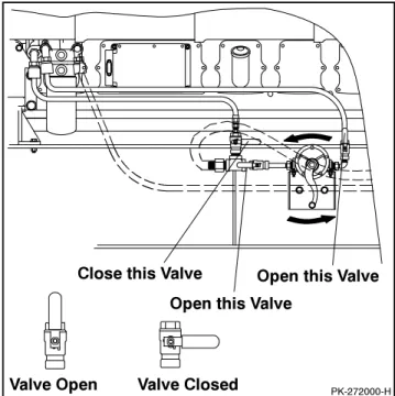
3.5.1 Bleeding Air from Fuel System . . . .140
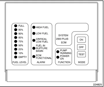
3.5.2 Subbase Fuel Day Tank Electronic Control Module (ECM) . . . .141
3.5.3 Subbase Inner Fuel Tank Alarm . . . .142
3.6 Gas Fuel Systems (REZG_ and REZX_/RZX_ models) . . . .142
3.6.1 Gas Fuel System Concept (Single Fuel) . . . .142
3.6.2 LPG Liquid Withdrawal Fuel System Concept . . . .142
3.6.3 Natural Gas and LPG Conversion . . . .143
3.6.4 Fuel System Changeover Kits (Dual Fuel) . . . .143
3.6.5 Crankcase Ventilation (CCV) Heater Kit GM78171-KP1 (125/150REZG models) . . . .145
3.7 Cooling System . . . .145
3.7.1 Coolant Level Check. . . .145
3.7.2 Cooling System Component Inspection. . . .146
3.7.3 Procedure to Drain Cooling System. . . .146
3.7.4 Procedure to Flush and Clean Cooling System . . . .146
3.7.5 Procedure to Refill Cooling System . . . .146
3.8 Radiator Fan Bolt Retorque. . . .147
3.9 Radiator Expansion Joint Loosening—Initial Setup Only . . . .148
3.10 Radiator Fan Bearing Lubrication. . . .148
3.11 Battery. . . .149
3.11.1 Clean Battery . . . .149
3.11.2 Electrolyte Level Inspection. . . .150
Table of Contents, continued
3.12 Detroit Diesel Engine Control Systems . . . .152
3.12.1 Features . . . .152
3.12.2 DDEC Engine Diagnostics. . . .152
3.13 Engine Control Systems. . . .153
3.14 Storage Procedure . . . .153
3.14.1 Lubricating System . . . .153
3.14.2 Cooling System . . . .153
3.14.3 Fuel System . . . .154
3.14.4 Internal Engine Components (Gas-Fueled Engines). . . .154
3.14.5 Exterior . . . .154
3.14.6 Battery. . . .154
Section 4 General Troubleshooting. . . .155
4.1 General Troubleshooting Chart. . . .156
4.2 Controller Display and Voltage Regulation Troubleshooting Chart . . . .159
Section 5 Generator Set Reconnection . . . .161
5.1 Introduction . . . .161
5.2 Voltage Reconnection Procedure. . . .162
Section 6 Accessories. . . .167
6.1 Accessories and Connections. . . .167
6.1.1 Audiovisual Alarm Kit . . . .167
6.1.2 Common Failure Relay Kit. . . .168
6.1.3 Controller (Customer) Connection Kit . . . .168
6.1.4 Float/Equalize Battery Charger Kit with Alarm Option. . . .168
6.1.5 Ground Fault Annunciation . . . .170
6.1.6 Idle (Speed) Mode Feature . . . .171
6.1.7 Low Fuel (Level/Pressure) Switch . . . .172
6.1.8 Prime Power Switch Kit . . . .172
6.1.9 Remote Emergency Stop Kit . . . .173
6.1.10 Remote Reset Feature . . . .173
6.1.11 Remote Serial Annunciator . . . .174
6.1.12 Remote Speed Adjustment Potentiometer Kit (Non-ECM Models) . . . .181
6.1.13 Run Relay Kit. . . .181
6.1.14 Shunt-Trip Line Circuit Breaker. . . .181
6.1.15 Single-Relay Dry Contact Kit. . . .182
6.1.16 Ten-Relay Dry Contact Kit . . . .182
6.1.17 Twenty-Relay Dry Contact Kit . . . .184
6.1.18 Wireless Monitor . . . .185
6.2 Accessory Connections . . . .186
Appendix A Abbreviations . . . 193
Appendix B User-Defined Settings . . . 195
Appendix C Voltage Regulator Definitions and Adjustments . . . 202
Appendix D Alternator Protection . . . 208
Safety Precautions and Instructions
IMPORTANT SAFETY INSTRUCTIONS.Electromechanical equipment, including generator sets, transfer switches, switchgear, and accessories, can cause bodily harm and pose life-threatening danger when improperly installed, operated, or maintained. To prevent accidents be aware of potential dangers and act safely. Read and follow all safety precautions and instructions. SAVE THESE INSTRUCTIONS.
This manual has several types of safety precautions and instructions: Danger, Warning, Caution, and Notice.
DANGER
Danger indicates the presence of a hazard that will cause severe
personal injury, death, or
substantial property damage.
WARNING
Warning indicates the presence of a hazard that can cause severe
personal injury, death, or
substantial property damage.
CAUTION
Caution indicates the presence of a hazard thatwillorcan cause minor
personal injuryorproperty damage.
NOTICE
Notice communicates installation, operation, or maintenance information that is safety related but not hazard related.
Safety decals affixed to the equipment in prominent places alert the operator or service technician to potential hazards and explain how to act safely. The decals are shown throughout this publication to improve operator recognition. Replace missing or damaged decals.
Accidental Starting
Accidental starting.
Can cause severe injury or death.
Disconnect the battery cables before working on the generator set. Remove the negative (--) lead first when disconnecting the battery. Reconnect the negative (--) lead last when reconnecting the battery.
WARNING
Disabling the generator set. Accidental starting can cause severe injury or death. Before working on the generator set or connected equipment, disable the generator set as follows: (1) Move the generator set master switch to the OFF position. (2) Disconnect the power to the battery charger. (3) Remove the battery cables, negative (--) lead first. Reconnect the negative (--) lead last when reconnecting the battery. Follow these precautions to prevent starting of the generator set by an automatic transfer switch, remote start/stop switch, or engine start command from a remote computer.
Battery
Sulfuric acid in batteries.
Can cause severe injury or death.
Wear protective goggles and clothing. Battery acid may cause blindness and burn skin.
WARNING
Explosion.
Can cause severe injury or death. Relays in the battery charger cause arcs or sparks.
Locate the battery in a well-ventilated area. Isolate the battery charger from explosive fumes.
WARNING
Battery electrolyte is a diluted sulfuric acid. Battery acid can cause severe injury or death.Battery acid can cause blindness and burn skin. Always wear splashproof safety goggles, rubber gloves, and boots when servicing the battery. Do not open a sealed battery or mutilate the battery case. If battery acid splashes in the eyes or on the skin, immediately flush the affected area for 15 minutes with large quantities of clean water. Seek immediate medical aid in the case of eye contact. Never add acid to a battery after placing the battery in service, as this may result in hazardous spattering of battery acid.
Battery acid cleanup. Battery acid can cause severe injury or death.
Battery acid is electrically conductive and corrosive. Add 500 g (1 lb.) of bicarbonate of soda (baking soda) to a container with 4 L (1 gal.) of water and mix the neutralizing solution. Pour the neutralizing solution on the spilled battery acid and continue to add the neutralizing solution to the spilled battery acid until all evidence of a chemical reaction (foaming) has ceased. Flush the resulting liquid with water and dry the area.
Battery gases. Explosion can cause severe injury or death.Battery gases can cause an explosion. Do not smoke or permit flames or sparks to occur near a battery at any time, particularly when it is charging. Do not dispose of a battery in a fire. To prevent burns and sparks that could cause an explosion, avoid touching the battery terminals with tools or other metal objects. Remove all jewelry before servicing the equipment. Discharge static electricity from your body before touching batteries by first touching a grounded metal surface away from the battery. To avoid sparks, do not disturb the battery charger connections while the battery is charging. Always turn the battery charger off before disconnecting the battery connections. Ventilate the compartments containing batteries to prevent accumulation of explosive gases.
Battery short circuits. Explosion can cause severe injury or death.
Short circuits can cause bodily injury and/or equipment damage. Disconnect the battery before generator set installation or maintenance. Remove all jewelry before servicing the equipment. Use tools with insulated handles. Remove the negative (--) lead first when disconnecting the battery. Reconnect the negative (--) lead last when reconnecting the battery. Never connect the negative (--) battery cable to the positive (+) connection terminal of the starter solenoid. Do not test the battery condition by shorting the terminals together.
Engine Backfire/Flash
Fire
Fire.
Can cause severe injury or death.
Do not smoke or permit flames or sparks near fuels or the fuel system.
WARNING
Servicing the fuel system. A flash fire can cause severe injury or death. Do not smoke or permit flames or sparks near the carburetor, fuel line, fuel filter, fuel pump, or other potential sources of spilled fuels or fuel vapors. Catch fuels in an approved container when removing the fuel line or carburetor.
Servicing the air cleaner. A sudden backfire can cause severe injury or death. Do not operate the generator set with the air cleaner removed.
Combustible materials. A fire can cause severe injury or death.
Generator set engine fuels and fuel vapors are flammable and explosive. Handle these materials carefully to minimize the risk of fire or explosion. Equip the compartment or nearby area with a fully charged fire extinguisher. Select a fire extinguisher rated ABC or BC for electrical fires or as recommended by the local fire code or an authorized agency. Train all personnel on fire extinguisher operation and fire prevention procedures.
Exhaust System
Carbon monoxide.
Can cause severe nausea,
fainting, or death.
The exhaust system must be leakproof and routinely inspected.
WARNING
Generator set operation. Carbon
monoxide can cause severe
nausea, fainting, or death. Carbon monoxide is an odorless, colorless, tasteless, nonirritating gas that can cause death if inhaled for even a short time. Avoid breathing exhaust fumes when working on or near the generator set. Never operate the generator set inside a building unless the exhaust gas is piped safely outside. Never operate the generator set where exhaust gas could accumulate and seep back inside a potentially occupied building.
Carbon monoxide symptoms.
Carbon monoxide can cause severe nausea, fainting, or death. Carbon monoxide is a poisonous gas present in exhaust gases. Carbon monoxide is an odorless, colorless, tasteless, nonirritating gas that can cause death if inhaled for even a short time. Carbon monoxide poisoning symptoms include but are not limited to the following:
D Light-headedness, dizziness
D Physical fatigue, weakness in joints and muscles
D Sleepiness, mental fatigue, inability to concentrate or speak clearly, blurred vision
D Stomachache, vomiting, nausea If experiencing any of these symptoms and carbon monoxide poisoning is possible, seek fresh air immediately and remain active. Do not sit, lie down, or fall asleep. Alert others to the possibility of carbon monoxide poisoning. Seek medical attention if the condition of affected persons does not improve within minutes of breathing fresh air.
Fuel System
Explosive fuel vapors.
Can cause severe injury or death.
Use extreme care when handling, storing, and using fuels.
The fuel system. Explosive fuel vapors can cause severe injury or death. Vaporized fuels are highly explosive. Use extreme care when handling and storing fuels. Store fuels in a well-ventilated area away from spark-producing equipment and out of the reach of children. Never add fuel to the tank while the engine is running because spilled fuel may ignite on contact with hot parts or from sparks. Do not smoke or permit flames or sparks to occur near sources of spilled fuel or fuel vapors. Keep the fuel lines and connections tight and in good condition. Do not replace flexible fuel lines with rigid lines. Use flexible sections to avoid fuel line breakage caused by vibration. Do not operate the generator set in the presence of fuel leaks, fuel accumulation, or sparks. Repair fuel systems before resuming generator set operation.
Explosive fuel vapors can cause severe injury or death. Take additional precautions when using the following fuels:
Gasoline—Store gasoline only in approved red containers clearly marked GASOLINE.
Propane (LP)—Adequate ventilation is mandatory. Because propane is heavier than air, install propane gas detectors low in a room. Inspect the detectors per the manufacturer’s instructions.
Natural Gas—Adequate ventilation is mandatory. Because natural gas rises, install natural gas detectors high in a room. Inspect the detectors per the manufacturer’s instructions.
Fuel tanks. Explosive fuel vapors can cause severe injury or death.
Gasoline and other volatile fuels stored in day tanks or subbase fuel tanks can cause an explosion. Store only diesel fuel in tanks.
Draining the fuel system. Explosive fuel vapors can cause severe injury or death. Spilled fuel can cause an explosion. Use a container to catch fuel when draining the fuel system. Wipe up spilled fuel after draining the system.
Gas fuel leaks. Explosive fuel vapors can cause severe injury or death. Fuel leakage can cause an explosion. Check the LP vapor gas or natural gas fuel system for leakage by using a soap and water solution with the fuel system test pressurized to 6--8 ounces per square inch (10--14 inches water column). Do not use a soap solution containing either ammonia or chlorine because both prevent bubble formation. A successful test depends on the ability of the solution to bubble.
LP liquid withdrawal fuel leaks. Explosive fuel vapors can cause severe injury or death. Fuel leakage can cause an explosion. Check the LP liquid withdrawal gas fuel system for leakage by using a soap and water solution with the fuel system test pressurized to at least 90 psi (621 kPa). Do not use a soap solution containing either ammonia or chlorine because both prevent bubble formation. A successful test depends on the ability of the solution to bubble.
Hazardous Noise
Hazardous noise. Can cause hearing loss.
Never operate the generator set without a muffler or with a faulty exhaust system.
CAUTION
Engine noise. Hazardous noise can cause hearing loss. Generator sets not equipped with sound enclosures can produce noise levels greater than 105 dBA. Prolonged exposure to noise levels greater than 85 dBA can cause permanent hearing loss. Wear hearing protection when near an operating generator set.
Hazardous Voltage/
Moving Parts
Hazardous voltage.
Will cause severe injury or death.
Disconnect all power sources before opening the enclosure.
DANGER
Hazardous voltage.
Can cause severe injury or death.
Operate the generator set only when all guards and electrical enclosures are in place.
Moving parts.
WARNING
Hazardous voltage.
Backfeed to the utility system can cause property damage, severe injury, or death.
If the generator set is used for standby power, install an automatic transfer switch to prevent inadvertent interconnection of standby and normal sources of supply.
WARNING
Grounding electrical equipment. Hazardous voltage can cause severe injury or death. Electrocution is possible whenever electricity is present. Ensure you comply with all applicable codes and standards. Electrically ground the generator set, transfer switch, and related equipment and electrical circuits. Turn off the main circuit breakers of all power sources before servicing the equipment. Never contact electrical leads or appliances when standing in water or on wet ground because these conditions increase the risk of electrocution.
High voltage test. Hazardous voltage can cause severe injury or death. Follow the instructions of the test equipment manufacturer when performing high-voltage tests on the rotor or stator. An improper test procedure can damage equipment or lead to generator set failure.
Testing the photo transistor circuit board. Hazardous voltage can cause severe injury or death. When the end cover is removed, do not expose the photo transistor circuit board mounted on the generator set end bracket to any external light source, as exposure to light causes high voltage. Keep foreign sources of light away from the photo transistor circuit board during testing. Place black electrical tape over the LED on the circuit board before starting the generator set.
Installing the photo transistor circuit board. Hazardous voltage can cause severe injury or death.
Ensure that the foil side of the photo transistor circuit board, the end of the shaft, and the threaded holes are clean and free of metal particles and chips. Metal debris may short-circuit the photo transistor circuit board and cause hazardous voltage in the generator set. Do not reconnect the generator set to the load until the AC voltmeter shows the correct output.
Installing the battery charger. Hazardous voltage can cause severe injury or death. An ungrounded battery charger may cause electrical shock. Connect the battery charger enclosure to the ground of a permanent wiring system. As an alternative, install an equipment grounding conductor with circuit conductors and connect it to the equipment grounding terminal or the lead on the battery charger. Install the battery charger as prescribed in the equipment manual. Install the battery charger in compliance with local codes and ordinances.
Connecting the battery and the battery charger. Hazardous voltage can cause severe injury or death.
Reconnect the battery correctly, positive to positive and negative to negative, to avoid electrical shock and damage to the battery charger and battery(ies). Have a qualified electrician install the battery(ies).
Servicing the day tank. Hazardous voltage can cause severe injury or death. Service the day tank electrical control module (ECM) as prescribed in the equipment manual. Disconnect the power to the day tank before servicing. Press the day tank ECM OFF pushbutton to disconnect the power. Notice that line voltage is still present within the ECM when the POWER ON light is lit. Ensure that the generator set and day tank are electrically grounded. Do not operate the day tank when standing in water or on wet ground because these conditions increase the risk of electrocution.
Short circuits. Hazardous
voltage/current can cause severe injury or death. Short circuits can cause bodily injury and/or equipment damage. Do not contact electrical connections with tools or jewelry while making adjustments or repairs. Remove all jewelry before servicing the equipment.
Engine block heater. Hazardous voltage can cause severe injury or death. The engine block heater can cause electrical shock. Remove the engine block heater plug from the electrical outlet before working on the block heater electrical connections.
Handling the capacitor. Hazardous voltage can cause severe injury or death. Electrical shock results from touching the charged capacitor terminals. Discharge the capacitor by shorting the terminals together.
(Capacitor-excited models only) Electrical backfeed to the utility. Hazardous backfeed voltage can cause severe injury or death. Install a transfer switch in standby power installations to prevent the connection of standby and other sources of power. Electrical backfeed into a utility electrical system can cause severe injury or death to utility personnel working on power lines.
Testing live electrical circuits. Hazardous voltage or current can cause severe injury or death. Have trained and qualified personnel take diagnostic measurements of live circuits. Use adequately rated test equipment with electrically insulated probes and follow the instructions of the test equipment manufacturer when performing voltage tests. Observe the following precautions when performing voltage tests: (1) Remove all jewelry. (2) Stand on a dry, approved electrically insulated mat. (3) Do not touch the enclosure or components inside the enclosure. (4) Be prepared for the system to operate automatically.
(600 volts and under)
Airborne particles.
Can cause severe injury or blindness.
Wear protective goggles and clothing when using power tools, hand tools, or compressed air.
WARNING
Servicing the generator set when it is operating. Exposed moving parts can cause severe injury or death.
Keep hands, feet, hair, clothing, and test leads away from the belts and pulleys when the generator set is running. Replace guards, screens, and covers before operating the generator set.
Heavy Equipment
Unbalanced weight.
Improper lifting can cause severe injury or death and equipment damage.
Do not use lifting eyes.
Lift the generator set using lifting bars inserted through the lifting holes on the skid.
Hot Parts
Hot coolant and steam.
Can cause severe injury or death.
Before removing the pressure cap, stop the generator set and allow it to cool. Then loosen the pressure cap to relieve pressure.
WARNING
Hot engine and exhaust system. Can cause severe injury or death.
Do not work on the generator set until it cools.
WARNING
Servicing the alternator. Hot parts can cause severe injury or death.
Avoid touching the alternator field or exciter armature. When shorted, the alternator field and exciter armature become hot enough to cause severe burns.
Servicing the exhaust system. Hot parts can cause severe injury or death. Do not touch hot engine parts. The engine and exhaust system components become extremely hot during operation.
Notice
NOTICE
This generator set has been rewired from its nameplate voltage to
246242
NOTICE
Voltage reconnection. Affix a notice to the generator set after reconnecting the set to a voltage different from the voltage on the nameplate. Order voltage reconnection decal 246242 from an authorized service distributor/dealer.
NOTICE
Canadian installations only. For standby service connect the output of the generator set to a suitably rated transfer switch in accordance with Canadian Electrical Code, Part 1.
Introduction
This manual provides operation instructions for 20 kW and larger generator sets equipped with the following controller:
D Decisionr 550, Software (Code) Version 2.10 or higher
Version 2.10 refers to the controller application software. To determine the generator set controller software version, go to Menu 20—Factory Setup and scroll down
to Code Version. The code version is the controller
software version.
Wiring diagram manuals are available separately. Refer to the engine operation manual for generator set engine scheduled maintenance information.
Information in this publication represents data available at the time of print. Kohler Co. reserves the right to change this publication and the products represented without notice and without any obligation or liability whatsoever.
Read this manual and carefully follow all procedures and safety precautions to ensure proper equipment operation and to avoid bodily injury. Read and follow the Safety Precautions and Instructions section at the beginning of this manual. Keep this manual with the equipment for future reference.
The equipment service requirements are very important to safe and efficient operation. Inspect the parts often and perform required service at the prescribed intervals. Maintenance work must be performed by appropriately skilled and suitably trained maintenance personnel familiar with generator set operation and service. The disk supplied with this generator set is a backup copy of the generator set personality program containing data specific to the engine and alternator. The engine and alternator data was preprogrammed in the controller at the factory and no further use of the disk should be necessary. Typically, your authorized distributor stores this disk for possible future use such as controller replacement or other circumstances requiring a backup.
Abbreviations
This publication makes use of numerous abbreviations. Typically, the word(s) are spelled out along with the abbreviation in parentheses when shown for the first time in a section. Appendix A, Abbreviations, also includes many abbreviation definitions.
List of Related Materials
Separate literature contains communication and software information not provided in this manual. Figure 1 lists the available literature part numbers.
Communication and Software
Manual Description Literature Part No.
550 Controller Spec Sheet G6-46 Generator Set/Controller
Wiring Diagram Manual
Multiple Part Numbers Contact your Distributor/Dealer 550 Communications Spec Sheet G6-50 Monitor III Converters, Connections,
and Controller Setup TT-1405 Monitor III Software Spec Sheet G6-76 Monitor III Converter,
Modbusr/Ethernet Spec Sheet G6-79 Monitor III Software Operation Manual TP-6347 ModbusrCommunications Protocol
Operation Manual TP-6113
Setup and Application Manual TP-6140 Service Parts Controllers TP-6780 Program Loader Software Installation TT-1285 SiteTechtSoftware Operation Manual TP-6701 Remote Serial Annunciator (RSA) TT-1377 Remote Serial Annunciator (RSA II) TT-1485 Controller Service Replacement TT-1310 Figure 1 Related Literature
Service Assistance
For professional advice on generator set power requirements and conscientious service, please contact your nearest Kohler distributor or dealer.
D Consult the Yellow Pages under the heading Generators—Electric.
D Visit the Kohler Power Systems website at KohlerPower.com.
D Look at the labels and stickers on your Kohler product or review the appropriate literature or documents included with the product.
D Call toll free in the US and Canada 1-800-544-2444. D Outside the US and Canada, call the nearest regional
office.
Headquarters Europe, Middle East,Africa (EMEA)
Kohler Power Systems 3 rue de Brennus 93200 Saint Denis France Phone: (33) 1 49 178300 Fax: (33) 1 49 178301 Asia Pacific
Power Systems Asia Pacific Regional Office Singapore, Republic of Singapore
Phone: (65) 6264-6422 Fax: (65) 6264-6455
China
North China Regional Office, Beijing Phone: (86) 10 6518 7950
(86) 10 6518 7951 (86) 10 6518 7952 Fax: (86) 10 6518 7955
East China Regional Office, Shanghai Phone: (86) 21 6288 0500
Fax: (86) 21 6288 0550 India, Bangladesh, Sri Lanka
India Regional Office Bangalore, India
Phone: (91) 80 3366208 (91) 80 3366231 Fax: (91) 80 3315972 Japan, Korea
North Asia Regional Office Tokyo, Japan
Phone: (813) 3440-4515 Fax: (813) 3440-2727 Latin America
Latin America Regional Office Lakeland, Florida, USA Phone: (863) 619-7568 Fax: (863) 701-7131
Section 1 Specifications and Features
1.1 Introduction
The spec sheets for each generator set provide model-specific generator and engine information. The controller spec sheet provides specifications for this controller. Refer to the respective spec sheet for data not supplied in this manual. Consult the generator set service manual, installation manual, engine operation manual, and engine service manual for additional specifications.
1.2 Controller Features
The controller features include the annunciator lamps, digital display and keypad, switches and controls, and fuses and terminal strip. The following paragraphs detail the features by general topics.
The controller features, accessories, and menu displays depend upon the engine electronic control module (ECM) setup and features. Controller features apply to generator set models with ECM and non-ECM engines unless otherwise noted.
Note:Press any key on the keypad to turn on the controller lights and display. The lights and display turn off 5 minutes after the last keypad entry.
Note:Measurements display in metric or English. Use Menu 7—Generator System to change the measurement display.
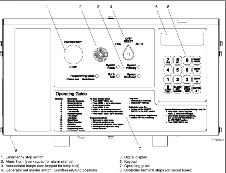
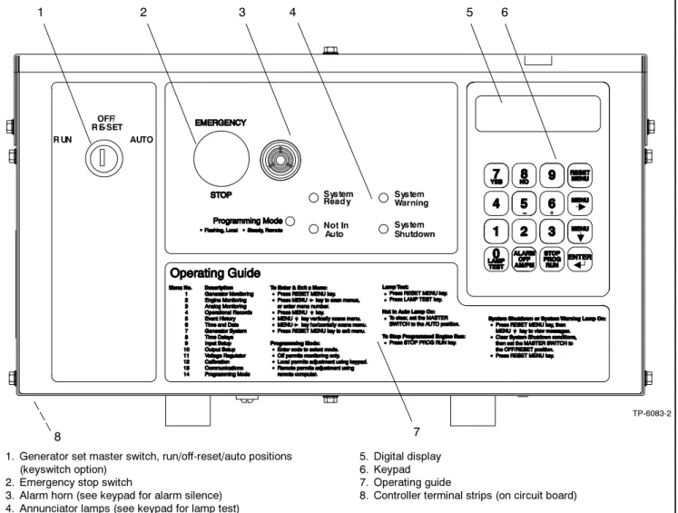
See Figure 1-1 for an illustration of the controller front panel. See Figure 1-2 for an illustration of the controller with the keyswitch option.
1. Emergency stop switch
2. Alarm horn (see keypad for alarm silence) 3. Annunciator lamps (see keypad for lamp test)
4. Generator set master switch, run/off-reset/auto positions
5. Digital display 6. Keypad 7. Operating guide
8. Controller terminal strips (on circuit board)
TP-6083-2
1 2 4 5
7 8
3 6
1. Generator set master switch, run/off-reset/auto positions (keyswitch option)
2. Emergency stop switch
3. Alarm horn (see keypad for alarm silence) 4. Annunciator lamps (see keypad for lamp test)
5. Digital display 6. Keypad 7. Operating guide
8. Controller terminal strips (on circuit board)
TP-6083-2
1 2 4 5
7 8
3 6
Figure 1-2 550 Controller with Keyswitch Option
1.2.1
Annunciator Lamps
Five annunciator lamps provide visual generator set status. See Figure 1-3.
TP-6083-2
Figure 1-3 Annunciator Lamps
System Ready. Green lamp illuminates when the generator set master switch is in the AUTO (automatic start) position and the system senses no faults. The unit is ready to start.
Not in Auto (NIA). Yellow lamp illuminates when the generator set master switch is not in the AUTO (automatic start) position.
Programming Mode. Yellow programming lamp indicates the user selected programming mode. See Figure 1-4.
Programming Lamp Programming Mode Selection
Lamp Flashing Local Programming Lamp Steady On Remote Programming Lamp Off Programming Disabled Figure 1-4 Programming Lamp Mode
Note:Find additional information for the programming mode lamp function and access to the local or remote programming modes in Section 2.8, Local Programming Mode On, Menu 14—Programming Mode.
System Warning. Yellow lamp identifies an existing fault condition that does not shut down the generator set. A continuing system warning fault condition may cause a system shutdown. Correct all system warnings as soon as practical.
See Section 2.3.5, System Warning Lamp, for definitions of the items listed.
The following conditions cause a system warning: D Engine functions:
d ECM yellow alarm
(DDC/MTU engine with MDEC/ADEC) d High battery voltage
d High coolant temperature d Low battery voltage d Low coolant temperature d Low fuel (level or pressure)* d Low oil pressure
d Speed sensor fault
d Starting aid (system status) d Weak battery
D General functions:
d Auxiliary—Analog up to 7 user-selectable inputs each with a high and low programmable warning level
d Auxiliary—Digital up to 21 user-selectable warnings
d Battery charger fault*
d Emergency power system (EPS) supplying load d Engine cooldown delay
d Engine start delay d Load shed kW overload d Load shed underfrequency
d Master switch not in AUTO (automatic start) position
d NFPA 110 fault (National Fire Protection Association)
d System ready (system status) D Alternator functions:
d AC sensing loss d Ground fault* d Overcurrent
* Requires optional input sensors.
Note:See Figure 2-8 in User Inputs for factory-reserved analog and digital inputs that are not user-selectable.
System Shutdown. Red lamp indicates that the generator set has shut down because of a fault condition. The unit will not start without resetting the controller, see Section 2.3.7, Controller Reset Procedure.
See Section 2.3.6, System Shutdown Lamp, for definitions of the items listed.
The following conditions cause a system shutdown: D Engine functions:
d Air damper closed (status), if equipped d Coolant temperature signal loss d ECM red alarm
(DDC/MTU engine with MDEC/ADEC) d Engine stalled (ECM only)
d High coolant temperature d High oil temperature d Low coolant level d Low oil pressure d Oil pressure signal loss d Overcrank
d Overspeed D General functions:
d Auxiliary—Analog up to 7 user-selectable inputs each with a high and low programmable
shutdown level
d Auxiliary—Digital up to 21 user-selectable shutdowns
d ECM communications loss (ECM models only) d Emergency stop
d Internal fault
d Master switch in OFF/RESET position d Master switch error
d Master switch open d NFPA 110 fault D Alternator functions:
d AC output overvoltage d AC output undervoltage
d Alternator protection against overload and short circuits
d Field overvoltage
(M4, M5, M7, or M10 alternator only) d Locked rotor (failed to crank)
d Overfrequency d Underfrequency
Note:See Figure 2-8 in User Inputs for factory-reserved analog and digital inputs which are not user-selectable.
1.2.2
Digital Display and Keypad
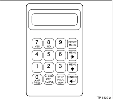
Figure 1-5 illustrates the digital display and keypad. Note:Press any key on the keypad to turn on thecontroller lights and display. The lights and display turn off 5 minutes after the last keypad entry.
The 2-line vacuum fluorescent display provides generator set and engine condition information. The 16-button keypad gives the user information access and local programming capability.
Keypad Functions
Alarm (Horn) Off key silences the alarm horn at the operator’s discretion. Place the generator set master switch in the AUTO position before silencing the alarm horn. See Section 2.3.7, Controller Reset Procedure, and Section 1.2.3, Switches and Controls.
AM/PM key provides time of day data entries when programming.
Enter ↵keyprovides confirmation entry when selecting menu or programming.
Lamp Test key tests the controller indicator lamps, horn, and digital display. See Section 1.2.3, Switches and Controls.
Menu down ↓ keyprovides navigation within menus when necessary.
Menu right → keyprovides navigation within menus when necessary.
Numeric 0--9 keysprovide numeric data entries when selecting menus or programming.
Reset Menu keyexits a menu, clears incorrect entries, and cancels the auto-scroll feature.
Stop Prog (Program) Run keyallows the user to stop any previously programmed generator set run sequence. See Section 1.2.3, Switches and Controls. Yes/No keys provides data answer entries when programming.
TP-5829-2
Figure 1-5 Digital Display and Keypad
Alternator Output Displays (Menu 1)
AC Amps displays the alternator output current. The display shows each line of 3-phase models.
AC Voltsdisplays the alternator output voltages. The display shows all line-to-neutral and line-to-line voltage combinations.
Alternator Duty Level displays the actual load kW divided by the nameplate kW rating as a percentage. Frequency displays the frequency (Hz) of alternator output voltage.
Hourmeterdisplays the generator set operating hours loaded and unloaded for reference in scheduling maintenance.
KVAdisplays the total and individual L1, L2, and L3 kVA. KVARdisplays the total and individual L1, L2, and L3 kVAR.
Power Factordisplays the kW/kVA and the individual line power factor values.
Wattsdisplays the total and individual L1, L2, and L3 kilowatts.
Engine Displays (Menu 2)
Some engine displays are available with selected generator set engines using engine ECMs only. The controller display shows N/A (not available) for items that are unavailable. See the controller spec sheet for applicable generator set models.
Ambient Temperaturedisplays the generator set area ambient temperature.
Charge Air Pressuredisplays the engine turbocharger boost air pressure.
Charge Air Temperature displays the engine turbocharger boost air temperature.
Coolant Leveldisplays the engine coolant level. Coolant Pressure displays the engine coolant pressure.
Coolant Temperature displays the engine coolant temperature.
Crankcase Pressure displays the engine crankcase pressure.
DC Voltsdisplays the voltage of starting battery(ies). Fuel Pressuredisplays the fuel supply pressure. Fuel Ratedisplays the calculated fuel consumption rate based on fuel injector outputs.
Fuel Temperature displays the fuel supply temperature.
Oil Leveldisplays the engine oil level as a percent of full capacity.
Oil Pressuredisplays the engine oil pressure. Oil Temperaturedisplays the engine oil temperature. RPM (Tachometer)displays the engine speed. Used Last Rundisplays the accumulated amount of fuel used since last reset by the engine DDEC reader.
Operational Record Displays (Menus 4 and 5)
The operational record displays events since last reset. See Section 2.8.4, Menu 4—Operational Records, for resetting procedure.
Engine Start Countdowndisplays the time remaining before the next generator set startup.
Event Historydisplays up to 100 stored system events including status, warnings, and shutdowns.
Last Start Datedisplays the date when the generator set last operated.
Number of Starts displays the total number of generator set startup events.
Number of Starts (Since) Last Maintenancedisplays the total number of generator set startup events since the last maintenance date.
Operating Days (Since) Last Maintenance displays the total number of days of operation since the last maintenance date. A counted day of operation can be 1--24 hours.
Run Time displays the total loaded hours, total unloaded hours, and total kW hours.
Run Time Since Maintenancedisplays the total loaded hours, total unloaded hours, and total kW hours.
Time Delay Displays (Menu 8)
The time delays are user adjustable. See Section 2.8.8, Menu 8—TIme Delays, for time delay adjustments. See Section 1.3.1, Status Event and Fault Specifications, for range and default settings.
Crank On/Crank Pausedisplays the time allocated for generator set crank on and crank pause in minutes:seconds.
Engine Cooldowndisplays the time delay for engine cooldown while the master switch is in the AUTO or RUN positions and not in the idle mode.
Engine Start displays the time delay before the generator set starts while the master switch is in AUTO or RUN positions.
Overcrank Shutdown (Number of) Crank Cycles displays the number of unsuccessful crank cycles (crank on/crank pause) before the generator set shuts down on an overcrank fault.
Overvoltage displays the time delay before the generator set shuts down because of an overvoltage condition.
Starting Aiddisplays the engine starting aid activation time.
Undervoltage displays the time delay before the generator set shuts down because of an undervoltage condition.
1.2.3
Switches and Controls
See Figure 1-6 and Figure 1-8 for switches and controls.
TP-6083-2
1. Emergency stop switch 2. Alarm horn
3. Generator set master switch
1 2 3
Figure 1-6 Switches and Alarm Horn
Note:Find additional switches and controls in Section 2.5.1, Keypad Operation.
Alarm Horn.The alarm horn alerts the operator or other attendants that a shutdown or warning condition exists. See Section 1.3, Controller Logic Specifications, for conditions. Place the generator set master switch in the AUTO position before silencing the alarm horn. The alarm horn cannot be silenced unless the generator set master switch is in the AUTO position. See Section 2.3.7, Controller Reset Procedure.
Alarm (Horn) Off. The keypad switch silences the alarm horn at the operator’s discretion. Place the generator set master switch in the AUTO position before silencing the alarm horn. Restore alarm horn switches at all locations including those on remote annunciator and audiovisual alarm kits to the normal position after correcting the fault shutdown to avoid reactivating the alarm horn. See Section 2.3.7, Controller Reset Procedure.
AM/PM. This keypad switch provides time of day data entries when programming.
Emergency Stop. The operator-activated pushbutton immediately shuts down the generator set in emergency situations. Reset the emergency stop switch after shutdown by pulling the switch knob outward. Use the emergency stop switch for emergency shutdowns only. Use the generator set master switch for normal shutdowns.
Generator Set Master Switch (Run/Off-Reset/Auto). This switch resets the controller fault lamps and start/stops the generator set. Refer to Section 2.3.1, Starting, Section 2.3.2, Stopping, and Section 2.3.3, Emergency Stop Switch Reset Procedure.
The generator set master switch with the keyswitch option (Figure 1-7) is available to meet appropriate local code requirements. The key is removable in the AUTO position only.
TP-6083-2
Figure 1-7 Generator Set Master Switch with Keyswitch Option
Lamp Test. The keypad switch tests the controller indicator lamps, horn, and digital display. Press the reset menu key before pressing the lamp test key. Stop Prog (Program) Run. Keypad switch allows the user to stop any previously programmed generator set run sequence.
1 2
TP-5829-2
1. Lamp test 2. Alarm horn silence 3. Stop program run
3
1.2.4
Controller Circuit Boards
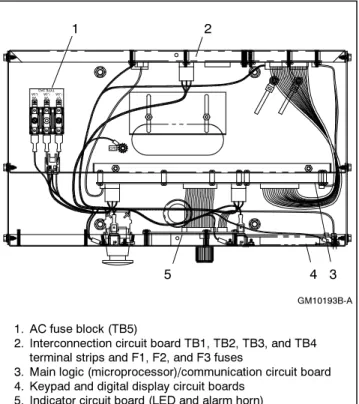
The controller has five circuit boards—indicator, interconnection, keypad, digital display, and main logic/ communication. See Figure 1-9 for circuit board locations. 1 2 GM10193B-A 3 4 1. AC fuse block (TB5)
2. Interconnection circuit board TB1, TB2, TB3, and TB4 terminal strips and F1, F2, and F3 fuses
3. Main logic (microprocessor)/communication circuit board 4. Keypad and digital display circuit boards
5. Indicator circuit board (LED and alarm horn)
5
Figure 1-9 Controller Circuit Boards and Fuses (Controller Top View)
Indicator (Status) Circuit Board includes the LED status lamps, alarm horn, and generator set master switch.
Interconnection Circuit Boardprovides the terminal strips to connect the controller (customer) connection board and/or dry contact kits and three DC fuses (F1, F2, and F3). See 6.1.3 for more information.
Keypad (Switch Membrane) Circuit Boardprovides the keypad to navigate the generator set displays and enter data.
Digital Display Circuit Board provides the vacuum fluorescent display (VFD) for monitoring the generator set functions and output values.
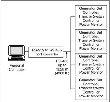
Main Logic (Microprocessor)/Communication Circuit Board provides the controller operation logic and provides PC communication locally (direct) or remotely (via modem) using RS-232 or RS-485 connectors.
1.2.5
Fuses
AC Circuit Fuses (TB5). Fuses are located inside the controller. See Figure 1-9.
D 1.5-Amp (V7) fuse protects L1 sensing input to interconnection circuit board.
D 1.5-Amp (V8) fuse protects L2 sensing input to interconnection circuit board.
D 1.5-Amp (V9) fuse protects L3 sensing input to interconnection circuit board.
DC Circuit Fuses fuses are located on the controller interconnection circuit board.
D 5-Amp Remote Annunciator (F1)fuse protects the dry contact kit if equipped and the controller panel lamps.
D 5-Amp Controller (F2) fuse protects the controller circuitry.
D 15-Amp Engine and Accessories (F3)fuse protects the engine/starting circuitry and accessories.
1.2.6
Terminal Strips and Connectors
Terminal strips and connectors for inputs and outputs are located on the interconnection circuit board. See Section 6, Accessories.TB1 Input Connection Terminal Stripprovides input connections for remote start and emergency stop (E-Stop).
TB2 Analog Input Connection Terminal Strip provides analog input connections, including non-ECM sensor connections.
TB3 Accessory Power Output Connection Terminal Stripsprovides a generator set power supply for factory use.
TB4 Digital Input Connection Terminal Strips connect external devices (engine ECM and user supplied) to the generator set digital inputs.
P23 Connector connects the interconnection circuit board to the controller (customer) connection terminal strip (connector P25) inside the junction box. See 6.1.3 for more information.
Figure 1-10 shows locations of the terminal strips on the controller interconnection circuit board. See Section 6.2, Accessory and Connections, for specific terminal identification information. Refer to the wiring diagrams for additional information on connecting accessories to the terminal strips.
1. TB1 terminal strip 2. TB2 terminal strip 3. P1 Connector ADV-6533-A 2 4 1 5 6 4. P23 Connector 5. TB3 terminal strip 6. TB4 terminal strip 3
Figure 1-10 Interconnection Circuit Board Terminal Strips and Connectors
1.2.7
Circuit Board Interconnections for
Calibration Procedure
The interconnection circuit board shown in Figure 1-11 contains a ribbon connector that requires disconnection during the calibration procedure in Menu 12— Calibration. Disconnect ribbon connector P2 prior to zeroing out (resetting) the auxiliary analog inputs.
2
4 1
1. Interconnection circuit board 2. P2 ribbon connector 3. P12 ribbon connector 4. Main logic circuit board
ADV-6533-A 4
Figure 1-11 Interconnection Circuit Board Ribbon Connector P2 (Top View of Circuit Board)
1.2.8
Communication Ports
The main logic circuit board contains several communication ports for Modbusr and KBUS connections. See Figure 1-12. Refer to the List of Related Materials in the Introduction for corresponding communication installation information.
1. P19—unused isolated connection (ISO2), RS-485 port 2. P21—KBUS isolated connection (ISO1), RS-485 port 3. P18—KBUS or Modbusr, RS-232 port
(Monitor III connection)
4. P20—Modbus, RS-485 port (Monitor III connection) 5. P22—ECM connector
6. Main logic circuit board
ADV-6533-A
1 2 3 4 5
6
Figure 1-12 Main Logic Circuit Board Communication Ports (Top View of Circuit Board)
1.3 Controller Logic Specifications
The controller logic specifications section is an overview of the various features and functions of the controller. Certain features function only when optional accessories are connected. See Section 2, Operation, for details.The default selection time delays and relay driver outputs (RDOs) are factory set and adjustable with the programming mode on (Menu 14). Some data entries require using a PC in the Remote Programming mode. See the monitor software operation manual for details. Inhibit Time Delay. The inhibit time delay is the time period following crank disconnect during which the generator set stabilizes and the controller does not detect a fault or status event. Select the desired inhibit time delay from 0 to 60 seconds.
TIme Delay (Shutdown or Warning). The time delay follows the inhibit time delay. The time delay is the time period between when the controller first detects a fault or status event and the controller warning or shutdown lamp illuminates. The delay prevents any nuisance alarms. Select the desired time delay from 0 to 60 seconds.
1.3.1
Status Event and Fault
Specifications
The table starting on the next page contains all status events and faults with ranges and time delays including items that do not have adjustments.
Note:The engine ECM may limit the crank cycle even if the controller is set to a longer time period.
Factory-Defined Settings
Status Event or Fault
Refer to
Menu Digital Display
Relay Driver Output (RDO)
Alarm
Horn Lamp Range Setting
Default Selection Inhibit Time Delay (sec.) Time Delay (sec.) Access Code (password) 14 User-Selectable 0 (zero)
AC Sensing Loss 10 AC SENSING LOSS
RDO-25 * On Warning Air Damper Control
(if used) ** 10 Air Damper Indicator (if used), see D20 ** Air/Fuel Module (AFM) Engine Start Delay] 10 AFM ENG START DELAY Fixed Air/Fuel Module (AFM) Remote Start] 10 AFM REMOTE START RDO-25] Off Air/Fuel Module (AFM) Shutdown (see D11)] Alternator Protection Shutdown 10 ALTERNATOR PROTECTION On Shutdown Analog Aux. Input 0 9 LOCAL BATT
VDC
Fixed Analog Aux. Inputs
A01--A07 9 USER-DEFINED A01--A07 On Shutdown or Warning
Default Values with Warning Enabled: HI warning 90% LO warning 10% HI shutdown 100% LO shutdown 1% 30 sec. inhibit, 5 sec. delay 0--60 0--60
Analog Aux. Input A01 (non-ECM only)
9 A01 COOLANT TEMP On Shutdown or Warning
Default Values with Warning Enabled: HI/LO warning and HI/LO shutdown are all engine dependent
30 sec. inhibit, 0 sec. delay warning, 5 sec. delay shutdown Analog Aux. Input
A02 (non-ECM only)
9 A02 OIL PRESSURE On Shutdown or Warning
Default Values with Warning Enabled: HI/LO warning and HI/LO shutdown are all engine dependent
(255 psi max.) 30 sec. inhibit, 0 sec. delay warning, 5 sec. delay shutdown Analog Aux. Input
A03] 9 A03 INTAKE AIR TEMP Shutdown or Warning
Default Values with Warning Enabled: HI/LO warning and HI/LO shutdown are all engine dependent
30 sec. inhibit, 0 sec. delay
warning Analog Aux. Input
A04 *
9 A04
FUEL LEVEL
Default Values with Warning Enabled: HI/LO warning are engine dependent
30 sec. inhibit, 0 sec. delay
warning Analog Aux. Input
A04]
9 A04
OIL TEMP
On Warning Default Values with Warning Enabled: HI/LO warning are engine dependent
30 sec. inhibit, 0 sec. delay
warning Analog Aux. Input
A06 VSG (Volvo, GM, Doosan only) 9, 12 A06 ANALOG AUXILIARY IN Off Volvo: 0.5V=1250 4.5V=8750 GM/Doosan 60 Hz: 0.5V=2375 4.5V=2625 50 Hz: 0.5V=2327 4.5V=2624 * All models, except Waukesha-powered models. ** NFPA applications
[ Non-paralleling applications [[ DDC/MTU engine with MDEC/ADEC
] Waukesha-powered models ]] FAA only
Factory-Defined Settings
Status Event or Fault Time Delay (sec.) Inhibit Time Delay (sec.) Default Selection Range Setting Lamp Alarm Horn Relay Driver Output (RDO) Digital Display Refer to MenuAnalog Aux. Input A07
9 A07
ANALOG VOLT ADJUST
±10% of system voltage over the range
of 0.5--4.5 VDC Battery Charger Fault
(see D01) ** Battle Switch (Fault Shutdown Override Switch) 9 BATTLE SWITCH
Off Warning Fixed
Block Heater Control[[
10 BLOCK HEATER CONTROL
RDO only Breaker Tripw 10 BREAKER
TRIP RDO-30 Off Warning Common Protective
Relay Outputw
10 COMMON PR OUTPUT
RDO-31w Off Warning Critical Overvoltage
Shutdown
10 CRITICAL OVERVOLTAGE
On Shutdown Fixed 275 volts (L1--L2)
Cyclic Cranking 8 Off 1--6 crank cycles
10--30 sec. crank on 1--60 sec. pause 3 15 sec. 15 sec. Defined Common Faults
(each input value is set separately)
10 DEFINED COMMON FAULT
RDO-18
(lead 32A) On Shutdownor Warning
Default shutdowns include: Emergency stop High coolant temp
Low oil pressure Overcrank Overspeed 30 sec. inhibit, 5 sec. delay 0--60 0--60 Detonation Shutdown (see D13)] Detonation Warning (see D12)] Digital Aux. Input D01--D21 9, 10 USER-DEFINED D01--D21 On Shutdown or Warning 30 sec. inhibit, 5 sec. delay 0--60 0--60
Digital Aux. Input D01 Battery Charger Fault ** 9, 10 D01 BATTERY CHARGER FAULT RDO-11 (lead 61)
On Warning Fixed 0 sec.
inhibit, 0 sec. delay Digital Aux. Input
D02 Low Fuel Warning ** 9, 10 D02 LOW FUEL WARNING RDO-08 (lead 63)
On Warning Fixed 0 sec.
inhibit, 0 sec. delay Digital Aux. Input
D03 Low Coolant Temperature ** 9, 10 D03 LOW COOLANT TEMP RDO-05 (lead 35)
On Warning Fixed 0 sec.
inhibit, 0 sec. delay Digital Aux. Input
D04 Field Overvoltage (M4, M5, M7, or M10 alt. only) 9, 10 D04 FIELD OVERVOLTAGE
On Shutdown Fixed 1 sec.
inhibit, 15 sec. delay Digital Aux. Input
D05 Breaker Closedw
9, 10 D05 BREAKER
CLOSED
Off Warning Fixed 0 sec.
inhibit, 0 sec. delay Digital Aux. Input
D06w 9, 10 D06 ENABLE SYNCH 20 sec. inhibit, 0 sec. delay Digital Aux. Input
D09 Low Fuel Pressure Shutdown (125RZG only) 9, 10 D09 LOW FUEL SHUTDOWN
On Shutdown Fixed 5 sec.
inhibit, 0 sec. delay Digital Aux. Input
D11 Air/Fuel Module (AFM) Shutdown]
9, 10 D11 AFM SHUTDOWN
On Shutdown Fixed 0 sec.
inhibit, 0 sec. delay * All models, except Waukesha-powered models. ** NFPA applications
[ Non-paralleling applications [[ DDC/MTU engine with MDEC/ADEC
] Waukesha-powered models ]] FAA only
Factory-Defined Settings
Status Event or Fault Time Delay (sec.) Inhibit Time Delay (sec.) Default Selection Range Setting Lamp Alarm Horn Relay Driver Output (RDO) Digital Display Refer to MenuDigital Aux. Input D12 Detonation Warning]
9, 10 D12 DETON WARNING
On Warning Fixed 2 sec.
inhibit, 0 sec. delay Digital Aux. Input
D13 Detonation Sensing Module (DSM) Shutdown] 9, 10 D13 DETON SHUTDOWN
On Shutdown Fixed 0 sec.
inhibit, 0 sec. delay Digital Aux. Input
D13 Knock Detection Module (KDM) Shutdown] 9, 10 D13 KNOCK SHUTDOWN
On Shutdown Fixed 0 sec.
inhibit, 0 sec. delay Digital Aux. Input D14
Low Coolant Level, (with LCL switch) **
9, 10 D14 LOW COOLANT LVL
RDO-19 On Shutdown Fixed 30 sec.
inhibit, 5 sec. delay Digital Aux. Input
D15 Remote Shutdown 9, 10 D15 REMOTE SHUTDOWN On Shutdown 0 sec. inhibit, 0 sec. delay Digital Aux. Input
D16 Remote Reset
9, 10 Digital Aux. Input
D17 VAR/PF mode
9, 10 Digital Aux. Input
D18 Voltage Lower 9, 10 Digital Aux. Input
D19 Voltage Raise
9, 10 Digital Aux. Input
D20 Air Damper Indicator (if used) **
9, 10 D20 AIR DAMPER
RDO-23 * (lead 56)
On Shutdown Fixed 0 sec.
inhibit, 0 sec. delay Digital Aux. Input
D21 Idle (speed) Mode Function
9, 10 D21 IDLE MODE
ACTIVE
RDO-21 Off Warning Fixed inhibit time 0 sec. inhibit, 60 sec. delay 0--600 or 9:99 for infinity ECM Red Alarm
(was MDEC Red Alarm) [[
10 ECM RED
ALARM On Shutdown
ECM Yellow Alarm (was MDEC Yellow Alarm)[[ 10 ECM YELLOW ALARM On Warning EEPROM Write Failure 10 EEPROM WRITE FAILURE On Shutdown Emergency Stop Shutdown 10 EMERGENCY STOP RDO-14 (lead 48) On Shutdown Engine Cooldown
(see Time Delay--)
Engine Derate Active 10 ENGINE DERATE ACTIVE (Engine) J1939 CAN Shutdown (ECM only) 10 J1939 CAN SHUTDOWN On Shutdown Engine Stalled
(ECM only) 10 STALLEDENGINE On Shutdown Engine Start
(see Time Delay--) EPS (Emergency Power System) Supplying Load 10 EPS SUPPLYING LOAD
RDO-22 Off Warning Fixed 1% of rated line current Field Overvoltage
(see D04)
* All models, except Waukesha-powered models. ** NFPA applications
[ Non-paralleling applications [[ DDC/MTU engine with MDEC/ADEC
Factory-Defined Settings
Status Event or Fault Time Delay (sec.) Inhibit Time Delay (sec.) Default Selection Range Setting Lamp Alarm Horn Relay Driver Output (RDO) Digital Display Refer to MenuFuel Level (see A04)
Fuel Valve Relay] 10 FUEL VALVE RELAY RDO-23] Generator Set Running 10 RDO-15 (lead 70R) Off Ground Fault Detected 10 GROUND FAULT On Warning High Battery Voltage 10 HIGH
BATTERY VOLTAGE
RDO-13 Off Warning 14.5--16.5 V (12 V)
29--33 V (24 V) 16 V (12 V)32 V (24 V) 10 High Coolant Temperature Shutdown 10 HI COOL TEMP SHUTDOWN RDO-03 (lead 36) On Shutdown 30 5 High Coolant Temperature Warning 10 HI COOL TEMP WARNING RDO-06 (lead 40) On Warning 30
High Oil Temperature
Shutdown 10 HI OIL TEMPSHUTDOWN On Shutdown 30 5
High Oil Temperature Warning] [[
10 HI OIL TEMP WARNING
On Warning 30
Idle (speed) Mode Function (see D21)
In Synchw 10 IN SYNCH RDO-29 * Intake Air Temperature Shutdown[[ 10 INTAKE AIR TEMP SDWN On Shutdown 30 Intake Air Temperature Warning [[ 10 INTAKE AIR TEMP WARN On Warning 30
Intake Air Temp Warning (see A03)] Intake Air Temp Shutdown (see A03)] Internal Fault Shutdown 10 INTERNAL FAULT On Shutdown J1939 CAN Shutdown (see Engine J1939 CAN Shutdown) Knock Shutdown (see D13)] kW Overload (see Load Shed) Load Shed kW Overload]]
10 LOAD SHED
KW OVER RDO-30]] Off Warning 80%--120% kW rating100% of with 5 sec.
delay
2--10
Load Shed Over Temperature[[ (Activated by a High Coolant Temp. shutdown) 10 LOAD SHED OVER TEMPERATURE RDO only Load Shed Underfrequency[ 10 LOAD SHED UNDER FREQUENCY
RDO-31[ Off Warning 59 Hz
(60 Hz) 49 Hz (50 Hz)
5
* All models, except Waukesha-powered models. ** NFPA applications
[ Non-paralleling applications [[ DDC/MTU engine with MDEC/ADEC
] Waukesha-powered models ]] FAA only
Factory-Defined Settings
Status Event or Fault Time Delay (sec.) Inhibit Time Delay (sec.) Default Selection Range Setting Lamp Alarm Horn Relay Driver Output (RDO) Digital Display Refer to Menu Locked Rotor Shutdown 10 LOCKED ROTOR On Shutdown Loss of ECM Communication (ECM only) 10 LOSS OF ECM COMM RDO-26 * On Shutdown 4 Loss of Field Shutdownw 10 SD LOSS OF FIELD On Shutdown Low Battery Voltage 10 LOW BATTERYVOLTAGE RDO-12 (lead 62) Off Warning 10--12.5 V (12 V) 20--25 V (24 V) 12 V (12 V) 24 V (24 V) 0 10
Low Coolant Level (see D14) (with LCL switch) ** Low Coolant Temperature (see D03) ** Low Coolant Temperature Shutdown[[ 10 LOW COOLANT TEMP SHUTDOWN On Shutdown
Low Fuel (Level or Pressure) Warning (see D02) ** Low Fuel Pressure Shutdown (see D09) (125RZG only) (Low) Oil Pressure Shutdown 10 OIL PRESSURE SHUTDOWN RDO-04 (lead 38) On Shutdown 30 5
(Low) Oil Pressure Warning 10 OIL PRESSURE WARNING RDO-07 (lead 41) On Warning 30
Maintenance Due 10 MAINTENANCE DUE
Master Not In Auto (Generator Set Switch) 10 MASTER NOT IN AUTO RDO-09 (lead 80) On Warning and Not In Auto Master Switch Error 10 MASTER
SWITCH ERROR
On Shutdown
Master Switch to Off 10 MASTER SWITCH TO
OFF
On Shutdown and Not
in Auto Master Switch Open 10 MASTER
SWITCH OPEN On Shutdown
NFPA 110 Fault ** 10 NFPA 110 FAULT RDO-10 (lead 32) On Shutdown or Warning No Air Temperature Signal Warning] 10 NO AIR TEMP SIGNAL On Warning 30 4 No Coolant Temperature Signal 10 NO COOL TEMP SIGNAL On Shutdown 30 4 No Oil Pressure
Signal 10 PRESSURENO OIL SIGNAL On Shutdown 30 4 No Oil Temperature Signal Warning] 10 NO OIL TEMP SIGNAL On Warning 30 4
Overcrank Shutdown 8, 10 OVER CRANK RDO-02 (lead 12)
On Shutdown 0--6 Cycles 3 Cycles * All models, except Waukesha-powered models. ** NFPA applications
[ Non-paralleling applications [[ DDC/MTU engine with MDEC/ADEC
] Waukesha-powered models ]] FAA only
Factory-Defined Settings
Status Event or Fault Time Delay (sec.) Inhibit Time Delay (sec.) Default Selection Range Setting Lamp Alarm Horn Relay Driver Output (RDO) Digital Display Refer to Menu Overcurrent 10 OVER CURRENT On Warning 110% 10 Over Current PR Shutdownw 10 SD OVER CURRENT PR On Shutdown Overfrequency Shutdown 7, 10 OVER FREQUENCY RDO-28 On Shutdown 102%--140% 110% Std. 103% FAA 10 Over Power Shutdownw 10 SD OVER POWER On Shutdown 102% Stdby 112% Prime Overspeed Shutdown7, 10 OVER SPEED RDO-01 (lead 39) On Shutdown 65--70 Hz (60 Hz) 55--70 Hz (50 Hz) 70 (60 Hz) 70 (50 Hz) 0.25 Overvoltage Shutdown 7, 8, 10 OVER VOLTAGE RDO-20 (lead 26) On Shutdown 105%--135% of nominal 115% 2-sec time delay[ 135% 10-sec time delayw 2--10 Password (see Access Code)
Pre Lube Relay] 10 PRE LUBE RELAY RDO-26] 4 Remote Reset (see D16) Remote Shutdown (see D15) Reverse Power Shutdownw 10 SD REVERSE POWER On Shutdown Speed Sensor Fault 10 SPEED
SENSOR FAULT
RDO-24 On Warning
Starting Aid (see Time Delay Starting Aid)
System Ready 10 RDO-17
(lead 60)
Off System Ready Time Delay Engine
Cooldown (TDEC) 8, 10 DELAY ENG COOLDOWN RDO-16 (lead 70C) Off 00:00--10:00 min:sec 5:00 Time Delay Engine
Start (TDES) 8, 10 DELAY ENG START Off 00:00--5:00 min:sec 00:01 Time Delay Starting
Aid
8, 10 Off 0--10 sec.
Underfrequency 7, 10 UNDER FREQUENCY
RDO-29] On Shutdown 80%--97% 97% FAA 90%[ 80%w 10 Undervoltage Shutdown 7, 8, 10 UNDER VOLTAGE RDO-27 On Shutdown 70%--95% 85% 10-sec time delay[ 70% 30-sec time delayw 5--30 Variable Speed Governor (VSG) (see A06) VAR/PF Mode (see D17) Voltage Lower (see D18)
* All models, except Waukesha-powered models. ** NFPA applications
[ Non-paralleling applications [[ DDC/MTU engine with MDEC/ADEC
] Waukesha-powered models ]] FAA only
Factory-Defined Settings
Status Event or Fault Time Delay (sec.) Inhibit Time Delay (sec.) Default Selection Range Setting Lamp Alarm Horn Relay Driver Output (RDO) Digital Display Refer to Menu Voltage Raise (see D19)Weak Battery 10 WEAK
BATTERY
Off Warning 60% of
nominal
2 * All models, except Waukesha-powered models. ** NFPA applications
[ Non-paralleling applications [[ DDC/MTU engine with MDEC/ADEC
] Waukesha-powered models ]] FAA only
w Paralleling applications
Calibration
Refer to
Menu Digital Display Range Setting Default Selection
Voltage Adjustment 11 VOLT ADJ ±10% of system voltage— Version 2.10 ±20% of system voltage— Version 2.11 or higher System voltage Underfrequency Unload Frequency Setpoint 11 FREQUENCY SETPOINT
40 to 70 Hz 1 Hz below system frequency (ECM) 2 Hz below system frequency (non-ECM) Underfrequency Unload
Slope
11 SLOPE 0--10% of rated voltage volts per cycle
3.1% of system voltage
Reactive Droop 11 VOLTAGE
DROOP
0--10% of system voltage 4% of system voltage VAR Control 11 KVAR ADJ 0 to rated kVAR generating
0 to 35% of rated kVAR absorbing
0 Power Factor (PF) Adjust
Control
11 PF ADJ 0.7 to 1.0 leading 0.6 to 1.0 lagging
0.8 lagging
Controller Gain 11 REGULATOR
GAIN
1--10000 100
VAR/PF Gain or Utility Stability
11 VAR/PF GAIN 1--10000 100
Figure 1-13 Settings for Controller Internal Voltage Regulation
1.3.2
Voltage Regulator and Calibration
Specifications
The 550 controller has a voltage regulation function that is internal to the processor. This means that no external voltage regulator is necessary. The voltage regulation of the controller uses root mean square (rms) sensing for fast response to changes in indicated and regulated voltages resulting in excellent regulation accuracy. RMS voltage regulation is available for both paralleling and utility application to control changes in the reactive loads due to load changes, prime mover speed variation, thermal drift, and other variations. See Figure 1-13 for data on the 550 controller voltage regulation. Refer to Appendix C to customize adjustments for specific applications.
1.3.3
Voltage Regulator Adjustments
The descriptions of the voltage regulator adjustments and features follow. See Appendix C, Voltage Regulator Definitions and Adjustments, for additional information.Voltage Adjustment. The voltage adjustment allows the user toenter the desired generator set output level. This regulated level setting is the average of the three line-to-line voltages in three-phase configurations or L1-to-L2 in single phase configurations.
Submenus display the individual line-to-line voltages. These voltages are for reference only and are relevant in unbalanced load conditions. The voltage adjust setpoint can be changed to accommodate an important phase in an unbalanced system.
Underfrequency Unload Frequency Setpoint. This adjustment affects the voltage droop (volts per Hz) when load is applied and underfrequency occurs. The underfrequency unload setting defines the setpoint where underfrequency starts. Any frequency below the setpoint causes the voltage to drop thus reducing the load allowing the engine speed to recover according to the underfrequency unload slope setting.
Engine speed recovery depends upon characteristics such as engine make, fuel type, load types, and operating conditions. The underfrequency unload setting should match the engine speed recovery characteristics for the application.
Underfrequency Unload Slope. This setting determines how much the voltage drops during an underfrequency condition. Typically, applying a large electrical load causes a dip in engine speed and frequency. The voltage regulator reduces voltage, allowing engine speed recovery. The volts-per-Hz setting determines theamount of voltage drop.
Reactive Droop. Reactive droop compensation provides reactive current flow adjustment in the generator set during generator set-to-generator set paralleling applications. Reactive droop reduces excitation levels with increasing reactive current. A reduced excitation level reduces generator set reactive current or generated VARs, improving reactive load sharing.
Enter the gain setting as apercentage of system voltage when full-rated load with 0.8 power factor is applied. Any loads less than full load force the voltage to drop by the ratio of reactive volt-amps (VARs) to rated VARs. VAR Control. VAR control is used in some utility paralleling applications. The excitation is regulated to maintain the reactive load rather than output voltage. The VAR adjust setting determines what reactive load is maintained at the generator set output. The VAR adjust is the total reactive load (sum of three phases). VAR control allows the user to define the direction of the reactive current out of the generator set (generating) or into the generator set (absorbing).
The utility supply, not the controller, determines terminal voltage. Engine fueling determines real power, measured in watts, using load sharing module control. Power Factor (PF) Adjust Control. Power factor control is used in some utility paralleling applications. The excitation is regulated to maintain PF rather than output voltage. The PF adjustment setting determines what PF is maintained at the generator set output. PF adjustment is the average of three phases.
Power factor is defined as the ratio of real power (watts) over the volt-amps. Power factor can be calculated as the cosine of the electrical angle between current and voltage. The cosine function is positive for angles between --90°and +90°including zero; and is negative for angles between --90 and +90 including 180°. This adjustment requires the user to determine whether the current leads or lags the voltage.
Regulator Gain.Regulator gain refers to the gain of the control system. Generally, the higher the gain the faster the system responds to changes and the lower the gain, the more stable the system.
If the voltage is slow the recover when loads are applied or removed, increase the regulator gain. If the voltage is unstable, decrease the regulator gain. Regulator gain is active only while not in the VAR/PF mode.
VAR/PF Gain. The VAR/PF gain also refers to the gain of the control system. Unlike the regulator gain, the response and stability of the system refers to the reactive current, or more specifically the VARs and/or power factor.
If the system is slow to recover to the desired V