04 August 2020
A multibody model for the optimization of hip arthroplasty in relation to range of movement / Zanetti, Elisabetta Maria; Bignardi, Cristina; Terzini, Mara; Putame, Giovanni; Audenino, Alberto Luigi. - In: THE AUSTRALASIAN MEDICAL JOURNAL. - ISSN 1836-1935. - ELETTRONICO. - 11:10(2018), pp. 486-491.
Original
A multibody model for the optimization of hip arthroplasty in relation to range of movement
Publisher: Published DOI:10.21767/AMJ.2018.3444 Terms of use: openAccess Publisher copyright
(Article begins on next page)
This article is made available under terms and conditions as specified in the corresponding bibliographic description in the repository
Availability:
This version is available at: 11583/2732026 since: 2019-05-03T12:29:49Z
A multibody model for the optimization of hip arthroplasty in relation to range
of movement
Elisabetta M. Zanetti
1, Cristina Bignardi
2, Mara Terzini
2, Giovanni Putame
2, and Alberto L.
Audenino
21. Department of Engineering, University of Perugia, Perugia, Italy
2. Department of Mechanical and Aerospace Engineering, Politecnico di Torino, Torino, Italy
486
RESEARCH
Please cite this paper as: Zanetti EM, Bignardi C, Terzini M, Putame G, Audenino AL. A multibody model for the optimization of hip arthroplasty in relation to range of movement. AMJ 2018;11(10):486–491.
https://doi.org/10.21767/AMJ.2018.3444
Corresponding Author:
Cristina Bignardi
Department of Mechanical and Aerospace Engineering, Politecnico di Torino, Cso Duca degli Abruzzi 24, 10129 Torino, Italy.
Email: [email protected]
ABSTRACT
Background
The dislocation of the prosthesized hip is a relevant post-operative complication;this adverse outcome is dependent on the specific patient anatomy and on the artificial joint design. The geometry of the reconstructed hip is one of the key factors and it is usually designed at the time of the pre-operative planning when the stem model and size, the head diameter and its offset, and the acetabular cup orientation are selected.
Aims
In this work, the authors have developed a numerical model to support the pre-operative planning, allowing assessing the hip range of motion, once the geometry of the implant has been defined.
Methods
A multi-body model of a prosthesized hip has been developed, and a dislocating movement has been applied; the software is able to assess the entity of displacements
and of applied forces which can produce hip dislocation.
Results
As a proof of concept, multiple combinations of geometric factors have been examined that are the head diameter, the acetabular cup anteversion and its inclination, reaching a total number of 675 configurations. This software is able to analyse and compare all configurations in few minutes.
Conclusion
The developed numerical model can be a support to quickly compare a great number of solutions from the point of view of hip stability, reaching a comprehensive view of all possibilities, and giving a contribute to the final aim that is surgery optimization, in relation to each specific patient.
Key Words
Hip arthroplasty, ROM, dislocation, pre-operative planning, acetabular cup inclination, acetabular cup anteversion, head size, impingement
What this study adds:
1. What is known about this subject?
Hip dislocation is a relevant complication in hip arthroplasty; this adverse outcome is dependent on the specific patient anatomy and on the artificial joint design.
2. What new information is offered in this study?
This study introduced a methodology, based on multibody model, which allows optimising the choice of prosthetic components and their positioning in relation to dislocation risk.
3. What are the implications for research, policy, or practice?
The pre-operative planning of hip arthroplasty can take benefit from numerical methods able to foresee the final hip range of motion.
487
Background
Dislocation is a continuing problem in total hip arthroplasty; occurrence range from 2–11% in patients with primary surgeries and from 5–25% in revisions.1-3 Many factors play an influence on the propensity for dislocation: the most studied ones include acetabular cup geometry and orientation, prosthetic head size, stem neck diameter, stem anteversion. Generally, in the clinical practice, only the result of multiple coupled variations can be observed, while dedicated experimental and numerical studies can allow to isolate each contribution.4-6
Evaluation criteria include range of motion from impingement to the onset of subluxation, and resisting moment built-up during dislocation. Resisting moments have been seldom considered and require the simulation of both geometry and forces acting on the joint (articular force and muscle forces).
Bader et al.7 evaluated resisting moments experimentally, but they did not simulate the femoral bone and the acetabulum; a more detailed experimental study was performed by Bartz et al.8 who used cadaveric specimens and simulated seven muscles; they studied the influence of head diameter. Yoshimine9 introduced an analytical numerical model, however its application is limited to the study of prosthetic impingement, and to simple geometries. Scifert et al.10 introduced a finite element model and validated it experimentally, but only the prosthetic components were modelled; other authors11 employed CAD models.
A different approach has been here followed after having considered, on one side, that CAD models cannot give full information because the only output is geometric interference.12 On the other side, finite element models can result quite heavy and they are not justified unless distributed deformations play a substantial role or stress patterns are being inquired.6,13 Multibody models can be a good compromise: they allow to impose displacements and calculate resulting forces and moments straightforwardly;13,14 besides, they allow to design sensors to verify the occurrence of contacts between bodies, and even to simulate energy dissipation.15 The multibody model here built was tested performing a multivariate analysis in order to show the influence of acetabular cup inclination and anteversion on the range of movements.
Method
The multibody model was realised through Adams (MSC Software Corporation); simulated rigid bodies were: the
femur, half a pelvis, the prosthetic stem and the acetabular cup. Synthetic bones were considered at this stage, but personalised models built from a CT7 scan16 or from x-rays17 could be used. The geometries of the implanted femur and of the pelvis were here obtained through reverse engineering: a CT scan was performed for both; the scans were segmented through apposite software and the contour lines (obtained both for cortical and trabecular bones) were exported to 3D CAD software (Rhinoceros, Robert McNeel & Associates). This software allowed defining the external surfaces of the implanted femur and of the pelvis (Figure 1), which were successively exported to the multibody software. The femur and the pelvis were virtually implanted with a stem and an acetabular cup, respectively. The stem was of press-fit type, symmetric and was inserted with 0° anteversion. The acetabular cup was hemispherical and it was implanted in various positions, as detailed in the following.
The model required the definition of constrains: the pelvis was left free to translate along three orthogonal directions; the acetabular cup was fully bounded to the pelvis; the head could rotate inside the acetabular cup; the stem was fully bounded to the femur. In addition, contact functions were defined between the head and the acetabular cup, between the external surfaces of the femur and of the pelvis and between the prosthetic stem and the acetabular cup. Special care was devoted to the simulation of head- acetabular cup contact function: an exponential force/displacement law was hypothesised:
e
n
k
g
F
Where:
Fn stands for ‘normal’ force;
k depends on the stiffness of contacting bodies; e defines the exponent of force/displacement
curve
g is the displacement of one body towards the other one.
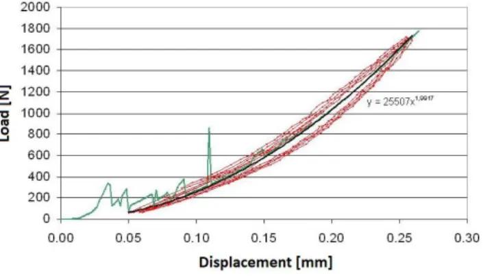
The parameters k and e were determined through experimental tests18 (Figures 2 and 3): the head was mounted on the translating head of a hydraulic testing machine; while the acetabular cup was simply laid on the basis of the testing machine. The comparison between the experimental curves and the interpolated one can be observed in Figure 3, having set e parameter equal to 1.2, and k stiffness constant equal to 8800N/mm.1.2
A typical dislocating movement was simulated putting the femur in 90° flexion, and applying internal/external rotation. This type of motion takes place when sitting in a
488
low chair, raising from a sitting position or picking up anobject from the floor.
The software was capable of detecting contact and interference of either bone or components thanks to apposite sensors; therefore, the incoming dislocation could be readily detected.
The design of experiments included three parameters: the acetabular cup inclination and anteversion and the head diameters (22, 28 or 32mm). Acetabular cup inclination and anteversion could vary from -15° to 55° and from 0° to 70°, respectively, with 5° steps; all combinations among these three factors were considered (the total number of experiments was equal to 15×15×3=675). Given a certain set up, the extreme internal rotation and external rotation were assessed, up to impingement.
Results
Figure 4 reports the range of motion versus acetabular cup anteversion for different acetabular cup inclinations. It should be reminded that indications here given are quite generic, considered the high variability of hip joint geometry in nature; in facts, patient-specific models are needed to perform a true pre-operative planning.
Some curves are missing or are not complete: this happens when a certain combination of acetabular cup anteversion/inclination and head size would not be possible because it would produce interference between prosthetic components.
Curves in Figure 4 reach a horizontal plateau when the transition from prosthetic impingement to bone impingement takes place: the reason is that the acetabular cup position has no influence on bone impingement. According to Figure 4, the maximum external rotation grows as acetabular cup anteversion increases (lower curves in Figure 4a have a negative slope), as acetabular cup inclination lowers and for larger head sizes; however this trend reaches a limit value at a ‘transition anteversion angle’ which depends on the head size and on the acetabular cup inclination; for example, with reference to the 22mm head size, the external rotation cannot exceed 122°, and this value is reached at 40° cup anteversion, given a 35° cup inclination (red circle in Figure 4a).
More in detail, this ‘transition anteversion angle’ can be very small for larger head size and for lower inclinations: for example, with reference to the 32mm head it is equal to 5°
for 35° cup inclination (red circle, Figure 4c), while it is equal to 35° for 45° cup inclination (black circle in Figure 4c). Upper curves in Figure 4 demonstrate that the limit internal rotation angle grows as acetabular cup anteversion grows (the upper curves have a positive slope), and for higher acetabular cup inclinations: for example, with reference to 22mm head size and 30° cup inclination, the limit internal rotation can reach 5° for 40° cup anteversion (black diamond in Figure 4a) or it can reach 15° for 55° cup anteversion (blue diamond in Figure 4a). The benefit given by growing acetabular cup anteversion takes place only beyond an anteversion angle which is lower for larger head size and for higher inclinations: for example, this minimum anteversion angle is equal to -5° for 60° cup inclination (blue triangle in Figure 4a), while it is equal to 25° for 35° cup inclination (red triangle in Figure 4a). Again there is a ‘boundary’ anteversion angle where a peak value of limit internal rotation is reached, this angle is smaller for larger head sizes and for larger acetabular cup inclinations; with reference to the 22mm head size, this boundary anteversion angle is equal to 55° for 30° cup inclination (blue diamond in Figure 4a), it is equal to 15° for 60° cup inclination (blue circle, Figure 4a); with reference to the 32mm head size, this same angle is equal to 0° for 30° cup inclination (blue circle in Figure 4c).
Finally, it should be stressed that the analysis of 675 prosthetic configurations has been accomplished in few minutes through a common personal computer.
Discussion
Various authors have given suggestions about the ‘optimal’ acetabular cup position. Widmer in one work,11 and Patel et al., in another work,11,17,19 suggested that a larger head diameter transforms a prosthetic impingement into a bone impingement; this assertion is here confirmed (curves in Figure 4c reach a plateau at lower anteversion angle, compared to curves in Figure 4a). Levinnek et al.20 introduced a “safety area”, where the acetabular cup inclination ranges from 30° to 50° and the acetabular cup anteversion ranges from 5° to 25°; according to Kummer et al.,21 10° acetabular cup anteversion and 45° inclination should be never exceeded. Indications given by these authors have been drawn considering the whole range of movements required by hip joint. According to Figure 4, giving absolute indications may be arbitrary, considering the relevant influence of the third analysed factor that is he head size. However it can be observed that the artificial joints here illustrated are particularly critical for what concerns the limit internal rotation (upper curves in Figure
489
4) which should be maximized: this target can be achievedeven with small cup inclination and anteversion (as long as they both are greater than 20°) when a large head size has been employed (Figure 4c). On the contrary, more stringent limits on cup inclination and anteversion are to be followed for smaller head sizes: if acetabular anteversion is smaller than 25°,20 cup inclination larger than 50° should be adopted (Figure 4a). Seemingly, Yoshimine9 clearly showed that acetabular cup inclination and anteversion cannot be regarded as independent parameters; a further proof of this is that, given a certain head size, the discontinuities of curves reported in Figure 4 do not occur at the same inclination angle.
The impact of acetabular cup anteversion and inclination on the maximum internal rotation at 90° flexion, agree with results reported by Robinson et al.,22 who showed that the maximum internal rotation in 90° of hip flexion increased as acetabular cup inclination and anteversion increased. A larger head size implies a wider joint range of motion (Figure 4a versus Figure 4c) as stated by many authors;23,24 however, according to Levinnek et al., there is no more benefit beyond 28 mm size20 and this statement is here confirmed by the results concerning the internal rotation (compare the upper curves in Figure 4b and 4c).
Some results in literature are significantly different from those here reported; this can be explained by morphological differences of simulated bodies: the stem shape (may be asymmetric, with different neck-shaft angles, neck length or cross-sectional geometry), and the acetabular cup (angular extension, external edge chamfers, etc.). Besides, here a synthetic femur was analysed, other authors considered cadaveric bones; in some cases,9 the only prosthetic components were modeled; lastly, the stem anteversion angle is usually larger than 0°; however, according to literature ‘combined anteversion’ that is the sum of femoral and acetabular anteversion is the key parameter, at least with reference to prosthetic impingement.25 According to this, results here obtained for a given ‘' anteversion, can be compared to those reported for 20° femoral anteversion and (-20) acetabular anteversion.
The sensibility of results towards the specific geometry gives evidence of the necessity of a patient-specific pre-operative planning, also considering the high variability of anatomic features among different races, genres and ages.12,26,27 This methodology can be extended to the analysis of other parameters such as the femoral anteversion: various authors demonstrated that the external rotation increases
as femoral anteversion decreases.22,28 Another important parameter is certainly the acetabular cup depth: in particular the mode of impingement is likely to change from bone impingement to prosthetic impingement as the acetabular cup moves deeper.7,29
The model should be further refined in order to be able to take into account soft-tissue structures which could further limit joint range of motion by causing impingement before bone or prosthetic component contact.30
Being able to perform more and more detailed pre-operative planning is becoming a mandatory issue also in relation to new possibilities offered by custom-made prostheses, realised by additive manufacturing.31
Conclusion
A multibody model of the prosthesized hip joint has been developed: this model has allowed demonstrating the influence of head size, acetabular cup inclination and anteversion on the joint range of motion; it can be further parametrised to simulate other geometrical parameters of the reconstructed joint. Since now, it can be a support to patient-specific pre-operative planning when the optimal positioning and the most suitable geometry of prosthetic components are to be established: given a certain patient, it is possible to individuate the range of motion resulting from each solution.
References
1. Berry DJ, von Knoch M, Schleck CD, et al. The cumulative long-term risk of dislocation after primary Charnley total hip arthroplasty. J Bone Joint Surg Am. 2004;86–A(1):9– 14.
2. Barrack RL, Thornberry RL, Ries MD, et al. The effect of component design on range of motion to impingement in total hip arthroplasty. Instr Course Lect. 2001;50:275– 80.
3. Amstutz HC, Lodwig RM, Schurman DJ, et al. Range of motion studies for total hip replacements. A comparative study with a new experimental apparatus. Clin Orthop Relat Res. 1975;111:24–30.
4. Boero Baroncelli A, Reif U, Bignardi C, et al. Effect of screw insertion torque on push-out and cantilever bending properties of five different angle-stable systems. Vet Surg. 2013;42(3):308–315.
5. Menicucci G, Ceruti P, Barabino E, et al. A preliminary in vivo trial of load transfer in mandibular implant-retained overdentures anchored in 2 different ways: allowing and counteracting free rotation. Int J Prosthodont. 2006;19(6):574–6.
490
6. Zanetti E, Bignardi C. Structural analysis of skeletal bodyelements: Numerical and experimental methods. in Biomechanical Systems Technology: Volume 3: Leondes CT, Ed. London, UK, 2009.
7. Bader R, Scholz R, Steinhauser E, et al. The influence of head and neck geometry on stability of total hip replacement: a mechanical test study. Acta Orthop. Scand. 2004;75(4):415–21.
8. Bartz RL, Nobel PC, Kadakia NR, et al., The effect of femoral component head size on posterior dislocation of the artificial hip joint. J Bone Joint Surg Am. 2000;82(9)1300–7.
9. Yoshimine F. The safe-zones for combined cup and neck anteversions that fulfill the essential range of motion and their optimum combination in total hip replacements. J Biomech. 2006;39(7):1315–1323. 10.Scifert CF, Noble PC, Brown TD, et al. Experimental and
computational simulation of total hip arthroplasty dislocation. Orthop Clin North Am. 2001;32(4):553–67. 11.Widmer KH. Impingementfreie Bewegung nach Hüft-TEP
– wie realisieren?. Z Orthop Unfall. 2016;154(4):392– 397.
12.Zanetti EM, Bignardi C. Mock-up in hip arthroplasty pre-operative planning. Acta Bioeng Biomech. 2013;15(3):123–8.
13.Zanetti EM, Terzini M, Mossa L, et al. A structural numerical model for the optimization of double pelvic osteotomy in the early treatment of canine hip dysplasia. Vet Comp Orthop Traumatol. 2017;30(4):256– 264.
14.Terzini M, Zanetti EM, Audenino AL, et al. Multibody modelling of ligamentous and bony stabilizers in the human elbow. Muscles Ligaments Tendons J. 2017;7(4):493–502.
15.Calì M, Oliveri SM, Ambu R, et al. An integrated approach to characterize the dynamic behaviour of a mechanical chain tensioner by functional tolerancing. Stroj Vestnik/J Mech Eng. 2018;64(4):245–257.
16.Adam F, Hammer DS, Pape D, et al. Femoral anatomy, computed tomography and computer-aided design of prosthetic implants. Arch Orthop Trauma Surg. 2002;122(5):262–268.
17.Zanetti EM, Crupi V, Bignardi C, et al. Radiograph-based femur morphing method. Med Biol Eng Comput. 2005;43(2):181–188.
18.Zanetti EM, Bignardi C, Audenino AL. Human pelvis loading rig for static and dynamic stress analysis. 2012;14(2):61–66.
19.Patel AB, Wagle RR, Usrey MM, et al. Guidelines for implant placement to minimize impingement during activities of daily living after total hip arthroplasty. J
Arthroplasty. 2010;25(8):1275–81.
20.Lewinnek GE, Lewis JL, Tarr R, et al. Dislocations after total hip-replacement arthroplasties. J Bone Joint Surg Am. 1978;60(2):217–20.
21.Kummer FJ, Shah S, Iyer S, et al. The effect of acetabular cup orientations on limiting hip rotation. J Arthroplasty. 1999;14(4):509–13.
22.Robinson RP, Simonian PT, Gradisar IM, et al. Joint motion and surface contact area related to component position in total hip arthroplasty. J Bone Joint Surg Br. 1997;79(1):140–6.
23.McCarthy TF, Nevelos J, Elmallah RK, et al. The Effect of Pelvic Tilt and Femoral Head Size on Hip Range-of-Motion to Impingement. J Arthroplasty. 2017;32(11):3544–3549.
24.Guyen O. Constrained liners, dual mobility or large diameter heads to avoid dislocation in THA. EFORT Open Rev. 2016;1(5):197–204.
25.Weber M, Woerner M, Craiovan B, et al. Current standard rules of combined anteversion prevent prosthetic impingement but ignore osseous contact in total hip arthroplasty. Int Orthop. 2016;40(12):2495– 2504.
26.Schmutz B, Kmiec S, Wullschleger ME, et al. 3D Computer graphical anatomy study of the femur: a basis for a new nail design. Arch Orthop Trauma Surg. 2017;137(3):321–331.
27.McCarthy TF, Alipit V, Nevelos J, et al. Acetabular Cup Anteversion and Inclination in Hip Range of Motion to Impingement. J Arthroplasty. 2016;31(9):264–268. 28.Ghaffari M, Nickmanesh R, Tamannaee N, et al. The
impingement-dislocation risk of total hip replacement: Effects of cup orientation and patient maneuvers. Conf Proc IEEE Eng Med Biol Soc. 2012;2012:6801–6804. 29.Bhaskar D, Rajpura A, Board T. Current concepts in
acetabular positioning in total hip arthroplasty. Indian J Orthop. 2017;51(4):386.
30.Kluess D, Zietz C, Lindner T, et al. Limited range of motion of hip resurfacing arthroplasty due to unfavorable ratio of prosthetic head size and femoral neck diameter. Acta Orthop. 2008;79(6):748–54.
31.Zanetti EM, Aldieri A, Terzini M, et al. Additively manufactured custom load-bearing implantable devices: Grounds for caution. Aus Med J. 2017;10(8):694–700.
PEER REVIEW
Not commissioned. Externally peer reviewed.
CONFLICTS OF INTEREST
491
FUNDING
No specific funding has been used for this research.
Figure 1: Multibody model of the prosthetised hip
Figure 2: Experimental set-up to assess contact parameters: the femoral head is pushed against the acetabular socket
Figure 3: Experimental and numerical load/displacement curves
Figure 4: Internal/external rotation versus acetabular cup
anteversion for different acetabular cup inclinations: a)