359
A Novel Algorithm for Four Phase (Multi-phase)
Source Side Load Balancing and Power Factor
Correction
First A. Zakir Husain1, Second B. R. K. Singh2 and Third C. S. N. Tiwari3
1
Department of Electrical & Electronics Engineering, National Institute of Technology, Hamirpur (H.P), India Email: [email protected]
2
Department of Electrical Engineering, MNNIT, Allahabad, (U.P), India Email: [email protected]
3
S P Memorial Institute of Technology, Bhiti Mahgaon, Kaushambi, (U.P) India Email: [email protected]
Abstract— Due to the potential benefits resulting from the use of more than the conventional three phases in transmission, some interest has also grown in the area of multi-phase (phase order more than three) machines in recent years. Multi-phase loads particularly in the form of inverter fed induction motor drives suited to high power and specialized applications, are receiving growing attention in the literature. This multi-phase source for such drive application may be derived from transformer connection (3-phase to 4-(3-phase) or by DC link 4-(3-phase inverters. These sources will face the problem of unbalance, harmonic distortion and poor power factor operation. In view of these developments, this paper deals with the supply side load balancing and power factor correction in such load circuits. The proposed compensation scheme uses the shunt current source compensation whose instantaneous values are determined by the instantaneous symmetrical component theory. An ideal compensator in place of physical realization of the compensator has been proposed in form of a current controlled voltage source inverter. The compensation schemes developed in the paper are tested for their validity on 4-phase (4-wire & 5-wire) circuits through extensive simulations for unbalanced loading and phase outages. The simulation results of the compensation theory and the ideal compensator verify the proposed compensation method.
Index Terms—Compensator, Load balancing, Multi-phase, Power factor correction
I. INTRODUCTION
Although multi-phase induction motor drives have been around for more than 3 decades, it is the last five years or so that have seen a tremendous increase in the volume of research related to these drive systems due to their several inherent benefits [1-10] such as reduced torque pulsation, harmonic content and current per phase without increasing the voltage per phase, higher reliability and increased power in the same frame as compared to their three-phase counterpart. Multi-phase inverter fed induction motor drives (especially 4-phase
and 6-phase) have been found to be quite promising for high power ratings and other specialized applications. The use of such multi drives and devices may be subjected to phase outages, unbalanced as well as non- linear loading similar to their three-phase counter parts. Such conditions may lead to variety of undesirable effects on the supply system such as additional losses in connecting lines and interfacing devices, oscillatory torques in ac machines, increased ripple in rectifiers, malfunctioning in sensitive equipments, harmonic and excessive neutral currents etc. It is therefore desired to have the balanced power system operation with minimum lower order harmonics even in the presence of such operations. A current literature survey reveals that a number of methods have been evolved for the compensation of harmonics and unbalances [11-28] for the conventional three phase systems. The majorities of the methods are based on the instantaneous reactive power theory [11-16], theory of symmetrical components [14-17], and reference frame theory [22-24]. Utilizing these theoretical concepts, techniques have been developed for balancing three phase load [14-15], power factor correction [15-16], voltage regulation [12-17] and meeting other objectives. This paper addresses the problem of balancing of an unbalanced 4-phase (multi-phase) load and power factor correction on supply side extending the well established approach [27] for 3-phse-phase system. Following the approach, the expressions of compensation current for a 4-phase (4-wire & 5-wire) load circuits have been derived. The proposed compensation methods have been verified by extensive simulation studies. The simulated results establish the validity of the proposed scheme.
II. COMPENSATION SYSTEM
An ideal voltage source is assumed to be connected to an arbitrary load
Z
L, drawing unbalanced current from the source. To make the source currents balanced, an external controlled current source is proposed to be connected to the load as shown in Fig.1. Let it be called Footnote: “IJJCE09-EE_RP_502 doc”, Zakir Husain. EEED, NITthe compensator system. Ideally it must be capable of making the source current balanced at desired power factor. The point of connection of compensator to power system is called point of common connection (PCC). The proposed compensation scheme can be applied to either four-phase four-wire or four-phase five-wire power system. In four-phase four-wire star connected load, the common point of the load ‘n’ is isolated from ‘N’, the common point of source where as in four-phase five-wire system, the neutral point is formed by connecting the nodes ‘n’ and ‘N’ and is also connected to the compensator at its common point
n
/ as shown in Fig.1. This has the advantage that the compensator currentscc cb ca
i
i
i
,
,
andi
cd are currents in independent circuits, and each phase of the compensator can supply currents independent of the other three phases which permits to compensate loads containing zero sequence currents. The shunt connection of controller allows compensating harmonics, reactive power and asymmetries of source currents, caused by non-linear and/or poor power factor loads. The expression for compensator current will be derived on the basis of instantaneous symmetrical component analysis of the load current.Load Z La Load Z Lb Load Z Lc Load Z Ld vs a vs b vs c vs d i s a i s b i s c i s d i l a i l b i l c i l d i c a i c b i c c i c d n ' n N
Ide al cu rre n t co m pe n sa tor
PCC
Fig.1 Compensation scheme for 4-phase star connected load. III. INSTANTANEOUS SYMMETRICAL
COMPONENTS THEORY
According to Wagner et al [29], an unbalanced four phasors (currents or voltages) of a four-phase system can be resolved into the four component systems of balanced phasors (Fig. 2) known as:
• The zero sequence system (zero phase differences);
• First- (positive) sequence system (four phasors are displaced 90 deg. relative to each other).
• The second-sequence system (two phasors are displaced 180 deg. relative to each other, each representing two phases, constituting two 2-phase zero sequences in opposition);
• Third-(negative) sequence systems (sequence in the opposite sense of rotation to that of the first-
sequence system)
Let the four sequences represented by means of subscripts 0,1,2,3 and the original unbalanced four-phase current phasors
I
a,
I
b,
I
c,
I
d with phase sequence abcd. The positive sequence components of balanced four-phase currentsI
a1,
I
b1,
I
c1,
I
d1have original phase sequence like the original unbalanced four-phase currents. The other three sets of components are as shown in Fig. 2. I a0 I c 0 I d0 I b0 Ia1 I d1 Ic1 I b1(a) Zero sequence system (b) First-(Positive sequence) system Id2 Ia2 Ic2 Ib2 Ia 3 I d 3 Ic 3 I b 3
(c) Second sequence system (d) Third-(negative) sequence system Fig. 2 Symmetrical Components of Four-Phase System As the original unbalanced four-phase phasors are resolved into four components, the components when they are added yield the original phasors. Therefore
⎪ ⎪ ⎭ ⎪ ⎪ ⎬ ⎫ + + + = + + + = + + + = + + + = 0 3 2 1 0 3 2 1 0 3 2 1 0 3 2 1 I I I I I I I I I I I I I I I I I I I I d d d d d c c c c c b c b b b a a a a a (1) A. Four-phase operator m
To express phasors algebraically, let the four-phase complex operator m be defined as,
0
1
0
exp
jπ/2=
+ j
.
. Any operation with this operator will result in a shift by 900 as shown in the Fig. 3.1 m
m2
m3
Fig. 3 Phasor diagram of the various powers of operator m
Some of the properties of operator ‘m’ are summarizes in (2)
⎪
⎪
⎭
⎪
⎪
⎬
⎫
=
+
+
+
−
=
∠
=
+
−
=
∠
=
+
=
∠
=
0
1
0
.
1
0
270
1
0
.
0
1
180
1
0
.
1
0
90
1
3 2 0 3 0 2 0m
m
m
j
m
j
m
j
m
(2) B. TransformationThe symmetrical components
I
a1,I
a2,
I
a3,
I
a0of a four-phase system defined above may be represented in matrix form by (3). ⎥ ⎥ ⎥ ⎥ ⎦ ⎤ ⎢ ⎢ ⎢ ⎢ ⎣ ⎡ ⎥ ⎥ ⎥ ⎥ ⎦ ⎤ ⎢ ⎢ ⎢ ⎢ ⎣ ⎡ = ⎥ ⎥ ⎥ ⎥ ⎦ ⎤ ⎢ ⎢ ⎢ ⎢ ⎣ ⎡ 3 2 1 0 3 2 1 2 2 1 2 3 d c b a m m m 1 m 1 m 1 m m m 1 1 1 1 1 I I I I a a a a I I I I (3)
The inverse relationship of equation (3) can be written as
⎥ ⎥ ⎥ ⎥ ⎦ ⎤ ⎢ ⎢ ⎢ ⎢ ⎣ ⎡ a3 a2 a1 a0 I I I I
)
4
/
1
(
=
⎥ ⎥ ⎥ ⎥ ⎦ ⎤ ⎢ ⎢ ⎢ ⎢ ⎣ ⎡ m m m m m m m m 2 3 2 2 3 2 1 1 1 1 1 1 1 1 ⎥ ⎥ ⎥ ⎥ ⎦ ⎤ ⎢ ⎢ ⎢ ⎢ ⎣ ⎡ d c b a I I I I (4)With the conventional rotation of current vectors in counter-clockwise direction, the instantaneous value of the currents can be determined and can be expressed as follows. ⎥ ⎥ ⎥ ⎥ ⎦ ⎤ ⎢ ⎢ ⎢ ⎢ ⎣ ⎡ 3 2 1 0 a a a a i i i i =
(
1
/
4
)
⎥ ⎥ ⎥ ⎥ ⎦ ⎤ ⎢ ⎢ ⎢ ⎢ ⎣ ⎡ m m m m m m m m 2 3 2 2 3 2 1 1 1 1 1 1 1 1 ⎥ ⎥ ⎥ ⎥ ⎦ ⎤ ⎢ ⎢ ⎢ ⎢ ⎣ ⎡ d c b a i i i i (5)Please note that the difference between (4) and (5) of phasor current Ia and instantaneous current
i
a, thetransformed currents
i
a0,i
a1,i
a2 &i
a3 are theinstantaneous symmetrical components of phase currents a
i
. Mathematically, it can be seen that instantaneous vectorsi
a1 andi
a3 are complex conjugate to eachother and
i
a0 is a real quantity, if instantaneous sourcecurrents are balanced. The neutral current
i
i
i
i
i
n=
a+
b+
c+
d will be non-zero if instantaneous current phasors are unbalanced and is also equal to4
i
ao.
The instantaneous symmetrical component
v
a0,v
a1,v
a2 &v
a3 of phase voltagev
a can be written as in term ofas
v
a, v
b, v
c, v
d ⎥ ⎥ ⎥ ⎥ ⎦ ⎤ ⎢ ⎢ ⎢ ⎢ ⎣ ⎡ 3 2 1 0 a a a a v v v v)
4
/
1
(
=
⎥ ⎥ ⎥ ⎥ ⎦ ⎤ ⎢ ⎢ ⎢ ⎢ ⎣ ⎡ 2 2 3 2 2 3 2 1 1 1 1 1 1 1 1 m m m m m m m m ⎥ ⎥ ⎥ ⎥ ⎦ ⎤ ⎢ ⎢ ⎢ ⎢ ⎣ ⎡ d c b a v v v v (6)IV. CALCULATION OF COMPENSATOR CURRENTS The principle of compensation is based on the fact that it is possible to compute, the compensator current for a system in real time shown in Fig.1 such that the source current (which is sum of the load current and the compensator current) is balanced and has the desired phase angle. This compensator current is calculated on the basis of instantaneous symmetrical component analysis of the load current. An explicit relation for the reference current will be derived in this section by applying multi-phase instantaneous power symmetrical component transformation. A compensated source is going to have balanced supply currents and therefore its zero sequence components will be zero. That is,
i
sa+
i
sb+
i
sc+
i
sd=
0
(7) The balanced phase currents at desired power factor angleφ
can be translated with the help of (5) & (6) into yet another equation (8)∠
{
vsa+mvsb+m2vsc+m3vsd} {
=∠isa+misb+m2isc+m3isd}
+φ (8)The instantaneous power in a 4-phase 5-wire system is given by
v
sai
sa+
v
sbi
sb+
v
sci
sc+
v
sdi
sd=
P
lavg (9)Solving (8), by taking
m
=
e
jπ/2 we obtain
φ
/
2
=
∠
(
A
−
B
)
(10) Where sb sa sb saj v
, B
i
j i
v
A
=
+
=
+
Taking tangent on both sides of (10), the following relation is obtained. sb sb sa sa sb sa sa sb
i
v
i
v
i
v
i
v
+
−
=
ξ
(11) Where,ξ
=
tan(φ
/
2
)
Equation (11) can be simplified and equation (12) can be derived. sa sb sa sa sb sb
i
v
v
v
v
i
⎟⎟
⎠
⎞
⎜⎜
⎝
⎛
+
−
=
ξ
(12) Also (9) can be simplified to derive (13)
i
sav
sa+
i
sbv
sb=
P
lavg/
2
(13) Employing the fact (Fig.2 (b)) thatisc=−isa,isd=−isb, and solving (13) and (12) together, the source currents are obtained and is given in (13).
(
)
(
)
lavg sb sa sa sb d b s lavg sb sa sb sa c a s P v v v v i P v v v v i , 2 2 , 2 2 2 2 + − ± = + + ± =ξ
ξ
(14)It is possible to write from Fig 1
)
,
,
,
(
p
a
b
c
d
i
i
i
cp=
lp−
sp=
(15) Using (14) in (15), equation (16) is obtained for generating compensator current⎪
⎪
⎪
⎪
⎪
⎪
⎭
⎪⎪
⎪
⎪
⎪
⎪
⎬
⎫
+
−
+
=
+
+
+
=
+
−
−
=
−
+
−
=
avg l b s a s a s b s d l d c avg l b s a s b s a s c l c c avg l b s a s a s b s b l b c avg l b s a s b s a s a l a cP
v
v
v
v
i
i
P
v
v
v
v
i
i
P
v
v
v
v
i
i
P
v
v
v
v
i
i
)
(
2
)
(
2
)
(
2
)
(
2
2 2 2 2 2 2 2 2ξ
ξ
ξ
ξ
(16)With the advent of high speed DSP processor computational speed has reduced substantially hence, relation for the compensator given by (16) can be computed online and therefore a controlled current source can be realized as compensator for load balancing.
V. SIMULATION RESULTS
The proposed compensation scheme for four-phase system has been verified by simulation. In this section, the simulation results will be presented and discussed.
A. Four-phase five wire system
The system shown in Fig.1 has the following specifications. The voltages
v
si(
i
=
a
,
b
,
c
,
d
)
and impedancesZ
i=
(
i
=
a
,
b
,
c
,
d
)
are given in (17) and (18)respectively.)
2
/
*
100
sin(
26
.
325
π
t
i
π
v
si=
−
(17)Where
i
*=
0
,
1
,
2
,
3
corresponds to phase a, b, c, d respectively10
15
j
Z
a=
+
,Z
b=
10
+
j
10
,20
10
j
Z
c=
+
,Z
d=
05
+
j
05
(18) In the simulation results, the system works with unbalanced load for one cycle (0.02 sec) and runs for another five cycle (0.10 sec) with the proposed compensator. It can be seen from Fig. 4(b) and Fig. 4(c) that the source currents (i
sp(
p
=
a
,
b
,
c
,
d
)
) and load currents (i
lp(
p
=
a
,
b
,
c
,
d
)
) are equal and unbalanced when compensator is off. At the time 0.02 sec., the compensator is turned on the source currents become perfectly balanced as shown in Fig. 4(c). In order to compensate unbalanced load currents, the instantaneouscompensator currents (
i
cp(
p
=
a
,
b
,
c
,
d
)
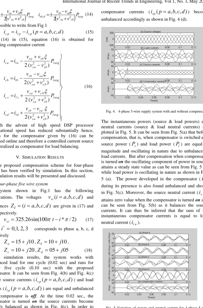
) become unbalanced accordingly as shown in Fig. 4 (d).
Fig. 4. 4-phase 5-wire supply system with and without compensator
The instantaneous powers (source & load powers) and neutral currents (source & load neutral currents) are plotted in Fig. 5.It can be seen from Fig. 5(a) that before compensation, that is, when compensator is switched off, source power (
P
s) and load power (P
l) are equal in magnitude and oscillating in nature due to unbalance in load currents. But after compensation when compensator is turned on the oscillating component of power in source attains a steady state value as can be seen from Fig. 5 (a) while load power is oscillating in nature as shown in Fig. 5 (a). The power developed in the compensator (P
c) during its presence is also found unbalanced and shown in Fig. 5(c). Moreover, the source neutral current (i
sN) attains zero value when the compensator is turned on and can be seen from Fig. 5(b) as it balances the source currents. It can thus be inferred that the sum of the instantaneous compensator currents is equal to load neutral current (i
ln).Fig. 5 Variation of power and neutral current for 4-phase 5-wire supply system
The variation of co-phasors-voltage and currents shows unity power factor operation with compensator as it is evident from Fig. 6 It can be seen from (18) that impedances are unbalanced and have reactive elements, but the currents are not only balanced but also operate at unity power factor with compensator
Fig. 6. (a)-(d) (1:10) Scaled source voltages (solid line), source currents (dashed line) load currents (hard solid line) 5-wire supply system
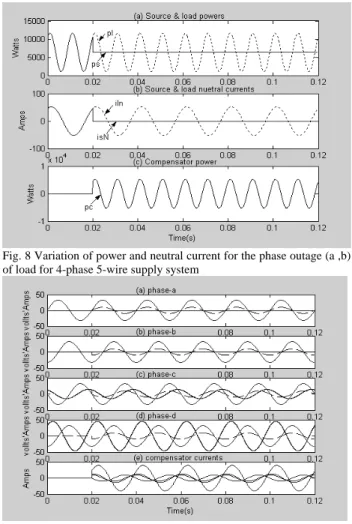
B. Load compensation for phase outages
As stated earlier that advantage of multiphase loads like motor is in its capability to operate with phase outages. The motor operates with degraded performance and source sees an unbalanced operation and therefore other loads connected to such a source get affected. The proposed compensator has also been tested with various combination of phase outages and it has been found that it works satisfactorily even with two phases open (with phase outages (a, b) in a 4- phase source. The results are shown in Fig.7 to Fig. 9.
Fig. 7 Variation of load currents, source currents and compensator currents when two phase (a , b) are out (from load side) from 4-phase 5-wire system.
Fig. 8 Variation of power and neutral current for the phase outage (a ,b) of load for 4-phase 5-wire supply system
Fig. 9.(a)- (d) (1:10) Scaled source voltages (solid line), source currents (dashed line), load currents (hard solid line) and (e) compensator
currents for phase outages (a,b) 4-phase 5wire supply system It can be observed from Fig. 7(c) and Fig. 8 (a) that the source currents and power are balanced when compensator is on. The voltage and current waveforms at unity power factor are portrayed in Fig. 9.
VI. CONCLUSION
Present paper concerns with a novel algorithm for load balancing and power factor correction on source side for 4-phase (multiphase) load circuit in the event of linear unbalance loading and phase outages have been proposed. The proposed scheme has been verified by simulations using MATLAB. It is found that unity power factor operation of the source is possible. A detailed study on source voltages, load currents, source currents, neutral currents and compensator currents has also been made during non-compensating and compensating period. The variations of the load, source and compensator powers are also analyzed. The simulations have confirmed unity power factor operation of the source in all cases as evidenced by the voltage and current waveforms. It has been shown that unity power factor operation of the source is possible.
An interesting aspect that has been observed in the simulation study is that 4-phase (multi-phase) system equipped with multi-phase compensator can work with
phase outages as high as 2 in 4-phase system without any degradation in supply system quality- a feature most valuable for multiphase sources and multiphase induction motor drives.
REFERENCES
[1] E. E. Ward, H. Harer, "Preliminary investigation of an inverter-fed 5- phase induction motor", Proc. IEE, vol. 116, no. 6, pp. 980-984, 1969.
[2] E. A. Kiligshim and C.M. Ong, High phase order induction motors-Part-I-Description and theoretical considerations, IEEE PAS-102, no.1 pp. 47-53, 1983
[3] E. A. Kiligshim and C.M. Ong, "High phase order induction motors-Part-II-Experimental results", IEEE PAS-102, no.1, pp.54-59, 1983
[4] J. R. Fu, T. A. Lipo, "Disturbance free operation of a multiphase current regulated motor drive with an opened phase", IEEE Trans. IA-30, no.5, pp.1267-1274, 1994 [5] Y. Zhao, and T.A. Lipo, "Modelling and control of
multiphase induction machine with structural unbalance", Part- I-Machine modeling and multi-dimensional current regulation, IEEE Trans, Energy conversion, EC-11, no. 3, pp. 570-577, 1996.
[6] H. A. Toliyat and H. Xu, "A novel direct torque control (DTC) method for five phase induction machine Proc. Applied Power Electronics conference & Symposium (APEC)-2000, Annual IEEE Conf., pp.162-168, 2000. [7] G. K. Singh, "Multi-phase induction machine drive
research-a survey, Electr. Power Syst. Res., vol. 61, pp. 139-147, 2002
[8] C. B. Jacobina, C. César de Azevedo, A. M. N. Lima, and L. A. Ribeiro, "Online estimation of the stator resistance and leakage inductance of a four-phase induction machine drive", IEEE Trans. On Power Electronics, vol. 19, no. 1, pp. 10-15, 2004.
[9] J. Apsley and S. Williamson, "Analysis of multiphase induction machine with winding faults", IEEE Transactions on industry applications, vol. 42, no.3, pp. 465-472, 2006.
[10]G. Q. Bao and S.Z. Jiang, “ A modular multi-phase permanent machine optimization for direct propulsion systemsIEEE Vehicle Power propulsion Conf., China, pp. 1-5, 2008
[11] L. Gyugyi, "Reactive power generation and control by thyristor circuits," IEEE Trans. On Ind. Appl. 1A-15, no.5, pp. 521-531, 1979
[12]H. Akagi,Y. Kanazawa, K. Fugita and A. Nabe, "Generalized theory of instantaneous reactive power and its application”, Electrical Engg. in Japan, vol. 103, no.4, pp. 58-66, 1983.
[13]H. Akagi, Y. Kanazawa and A. Nabe, "Instantaneous reactive power compensators comparing switching devices without energy storage components," IEEE Trans. Ind. Appl., vol. 1A-20, no.3, pp. 625-630, 1984.
[14] H, Akagi, A. Nabe and S. Atosh, "Control strategy of active power filters using multi voltage-source PWM converter”, IEEE Trans. Ind. Appl. vol.1A-22, no.3, pp. 460-465, 1986
[15]M. Z. Elsadek, "Balancing of unbalanced loads using static var compensators", Electr. .Pow.Syst. Res., (12), pp. 137-148, 1987.
[16]H. Watanabe, R. M. Stephan and M. Aredes, "New concepts of instantaneous active and reactive powers in
electrical systems with generic loads," IEEE Trans. On Power Delivery, vol. 8, no. 2, pp. 697-703, 1993.
[17]A. Kern and G. Schroder, "A novel approach to power factor control and balancing problems," Proc. , IEEE, IECON, 428-433, 1994
[18] Y. Suh, T.A. Lipo, “Modelling and analysis of instantaneous and reactive power for PWM AC/DC converter using generalized unbalanced network”, IEEE Trans. on Power Delivery vol. 21, n0.3, pp. 1530-1540, 2006.
[19]M. Adres and E.H. Watana, "New control algorithms for series and shunt three-phase four wire active power filters," IEEE Trans. Power Delivery, vol., 10, no. 3, pp.1649-1656, 1995.
[20]Peng and J.S. Lai, "Generalized instantaneous reactive power theory for three-phase power systems," IEEE Trans. Instrumentation and measurement, vol. 45, no.1, pp. 293-297, 1996.
[21]V. Soares, P. Verdelho and G. Marques, "A control method for active power filters under unbalanced non sinusoidal conditions”, IEE Conf. on power electronics and speed drives, no.429, pp. 120-124, 1996.
[22]P. Verdelho, and G.D. Marques, "An active power filter and unbalanced current compensator," IEEE Trans. On Industrial Electronics, vol. 44, no.3, pp. 321-328, 1997. [23]F. Z. Peng, G.W. Ott, Jr., and D.J. Adams, "Harmonic and
reactive power compensation based on the generalized instantaneous reactive power theory for three-phase four-wire systems," IEEE Trans.on power electroics, vol. 13, no. 6, pp. 1174-1181, 1998.
[24]P. Verdelho G.D. Marques, "A neutral current electronics compensator," IEEE, IECON 98, pp. 831-936, 1998. [25]V. Cardenas, N. Vazquez, C. Hernandes, S. Horta,
"Analysis and design of a three-phase sliding mode controller for a shunt active power filter," IEEE power electronics specialist conference-PESC'99, pp. 236-241, 1999
[26]Y. Suh, T.A. Lipo, “Modelling and analysis of instantaneous and reactive power for PWM AC/DC converter using generalized unbalanced network”, IEEE Trans. On Power Delivery vol.21, no. 3, 1530-1540, 2006 [27]A. Ghosh, A. Joshi, "A new approach to load balancing
and power factor correction in power distribution system," IEEE Trans. On power delivery, Vol. 15, No.1, 2000, pp. 417-422.
[28]S. V. Vazuez, J.A. Sanchez, J. M. Carrasco, J. I. Leon and E. Galvan, “ A model-based direct power control for three phase power converter,” IEEE Ttans. On Ind. Electronics, vol. 55, no.4, pp. 1647-1657, 2008
[29]C. F. Wagner, R. D. Evans and C. L. Fortescue, “Symmetrical components”, McGra-Hill, chapter XVI, 1933.