Dell™ PowerVault™ Modular Disk
Storage Manager User’s Guide
Notes and Notices
NOTE: A NOTE indicates important information that helps you make better use of
your computer.
NOTICE: A NOTICE indicates either potential damage to hardware or loss of data
and tells you how to avoid the problem.
____________________
Information in this document is subject to change without notice. © 2008 Dell Inc. All rights reserved.
Reproduction of these materials in any manner whatsoever without the written permission of Dell Inc. is strictly forbidden.
Trademarks used in this text: Dell, the DELL logo, PowerEdge and PowerVault are trademarks of Dell Inc.; Microsoft, Windows, Windows Server, MS-DOS, and Internet Explorer are either trademarks or registered trademarks of Microsoft Corporation in the United States and/or other countries. Red Hat and Red Hat Enterprise Linux are registered trademarks of Red Hat, Inc. SUSE is a registered trademark of Novell Inc.
Other trademarks and trade names may be used in this document to refer to either the entities claiming the marks and names or their products. Dell Inc. disclaims any proprietary interest in trademarks and trade names other than its own.
Contents
1
About This Guide
. . . .11
User Interface . . . 11 Summary Tab. . . 12 Configure Tab . . . 12 Modify Tab . . . 12 Tools Tab . . . 13 iSCSI Tab . . . 13 Support Tab . . . 13
Other Information You May Need . . . 14
2
About Your Storage Array
. . . .15
Access Virtual Disk . . . 15
Out-of-Band and In-Band Management . . . 16
Adding Storage Arrays . . . 17
Automatic Discovery of Storage Arrays . . . 17
Manual Addition of a Storage Array. . . 17
Naming Storage Arrays . . . 18
4 Contents
Password Guidelines. . . 22
Resetting a Password . . . 22
Connecting the Serial Cable . . . 22
System Setup for Password Reset . . . 23
Reset Password . . . 24
Changing Expansion Enclosure ID Numbers . . . 25
Configuring Alert Notifications . . . 25
Configuring E-mail Alerts. . . 25
Configuring SNMP Alerts . . . 27
Battery Settings . . . 28
Starting or Restarting the Host-Agent Software in Windows . . . 28
Starting or Restarting the Host-Agent Software in Linux. . . 29
3
Using iSCSI
. . . .31
Using the iSCSI Tab . . . 31
Changing the iSCSI Target Authentication . . . 32
Entering Mutual Authentication Permissions . . . 32
Creating CHAP Secrets. . . 32
Changing the iSCSI Target Identification . . . 34
Changing the iSCSI Target Discovery (Optional) . . . . 34
Configuring the MD3000i iSCSI Host Ports . . . 35
Advanced iSCSI Host Ports Settings. . . 35
Viewing iSCSI Statistics and Setting Baseline Statistics 37
Edit, Remove, or Rename Host Topology . . . 38
4
Event Monitor
. . . .41
Enabling the Event Monitor . . . 41
Disabling the Event Monitor . . . 42
5
About Your Host
. . . .43
Configuring Host Access . . . 43
Automatic Configuration . . . 44
Manual Configuration (using SAS HBA). . . 44
Manual Configuration (using iSCSI) . . . 45
Removing Host Access . . . 46
Host Groups . . . 47
Creating a Host Group . . . 47
Adding a Host to a Host Group. . . 47
Removing a Host From a Host Group . . . 48
Moving a Host to a Different Host Group . . . 48
Removing a Host Group . . . 49
Host Topology . . . 49
Host Context Agent. . . 50
6 Contents
Manual Configuration . . . 55
Hot Spare Drive Protection . . . 58
Automatically Configuring Hot Spares. . . 58
Manually Configuring Hot Spares . . . 59
Host-to-Virtual Disk Mapping. . . 60
Creating Host-to-Virtual Disk Mappings . . . 60
Modifying and Removing Host-to-Virtual Disk Mapping . . . 60
Changing Controller Ownership of the Virtual Disk 61
Storage Partitioning . . . 61
Disk Group and Virtual Disk Expansion. . . 62
Disk Group Expansion . . . 62
Virtual Disk Expansion . . . 62
Disk Group Migration . . . 63
Export Disk Group . . . 63
Import Disk Group . . . 64
Storage Array Media Scan . . . 65
Changing Media Scan Settings . . . 66
Suspending the Media Scan . . . 66
Microsoft Services . . . 67
Virtual Disk Service. . . 67
Volume Shadow-Copy Service. . . 67
7
Premium Feature—Snapshot Virtual Disks
69
Creating a Snapshot Virtual Disk Using the Simple Path 70 About the Simple Path . . . 71Preparing Host Servers to Create the Snapshot Using the Simple Path. . . 71
Creating the Snapshot Using the Simple Path. . . 73
Creating a Snapshot Virtual Disk Using the Advanced Path 75 About the Advanced Path . . . 75
Preparing Host Servers to Create the Snapshot Using the Advanced Path . . . 76
Creating the Snapshot Using the Advanced Path . 78
Specifying Snapshot Virtual Disk Names . . . 80
Snapshot Repository Capacity . . . 81
Re-creating Snapshot Virtual Disks . . . 82
Disabling a Snapshot Virtual Disk . . . 82
Preparing Host Servers to Re-create a Snapshot Virtual Disk . . . 83
Re-creating a Snapshot Virtual Disk. . . 84
8
Premium Feature—Virtual Disk Copy
. . .85
Creating a Virtual Disk Copy for an MSCS Shared Disk 86
Virtual Disk Read/Write Permissions. . . 87
Virtual Disk Copy Restrictions . . . 88
Creating a Virtual Disk Copy . . . 89
Preparing Host Servers to Create a Virtual Disk Copy. . . 89
Copying the Virtual Disk . . . 90
Storage Array Performance During Virtual Disk Copy . 91
8 Contents
Preparing Host Servers to Recopy a Virtual Disk . 93
Recopying the Virtual Disk . . . 94
Removing Copy Pairs . . . 95
9
Premium Feature—32 Partitions
. . . .97
10 Firmware Downloads
. . . .99
Downloading RAID Controller and NVSRAM Packages 100 Downloading Both RAID Controller and NVSRAM Firmware . . . . 100
Downloading Only NVSRAM Firmware . . . . 101
Downloading Non-redundant MSCS NVSRAM Firmware. . . . 101
Downloading Physical Disk Firmware . . . . 102
Downloading EMM Firmware. . . . 103
Firmware Upgrade to 07.xx . . . . 104
11 Troubleshooting Problems
. . . .107
Recovery Guru . . . . 107
Storage Array Profile . . . . 107
Device Health Conditions . . . . 107
SMrepassist Utility . . . . 108
Support Information Package. . . . 109
Recovering from an Unidentified Storage Array . . . . 110
A Enclosure Hardware Replacement, Maintenance,
and Configuration Considerations
113
Removing and Inserting Enclosure Management Modules on Attached Expansion Enclosures . . . . 113
Removing an EMM from the Expansion Enclosure 113 Inserting an EMM into an Expansion Enclosure. . 113 Removing and Inserting Physical Disks . . . . 114 MD3000 Maintenance Considerations . . . . 114 MD3000 Cluster Configuration Guidelines
for Standalone Host Servers . . . . 115
About This Guide
Dell™ PowerVault™Modular Disk (MD) Storage Manager software is used to create and manage multiple storage arrays. The software can be used on any host attached to the storage array, as well as on storage management stations connected to the same sub-network.
MD Storage Manager is a graphical user interface (GUI) with wizard-guided tools and a task-based structure designed to reduce the complexity of installation, configuration, management, and diagnostic tasks.
MD Storage Manager software also contains an optional event monitoring service that is used to send alerts when a critical problem with the storage array occurs and a command line interface (CLI) to access functions performed by MD Storage Manager.
This guide is intended for users who are already familiar with the basic functions of their storage array. Any differences in certain functions between supported operating systems are explained where applicable.
MD Storage Manager online help contains detailed answers to software-related questions. You can access online help by clicking Help located at the top right corner of the MD Storage Manager interface. Refer to your storage array’s Installation Guidefor information on installing the MD Storage Manager.
User Interface
The Storage Manager screen is divided into three parts:
• The Title Bar at the top of the screen displays the name of the application and the Dell logo.
• Beneath the Title Bar is the Array Selector, listing the MD Storage Array that is currently selected. The icon next to the array’s name indicates its condition. You can choose another array by clicking the down-arrow next to
12 About This Guide
• Beneath the Array Selector is the Content Area. Several tabs appear in this area to group the tasks you can perform on the selected array. When you click on a tab, the Content Area displays links for the tasks you can perform. The following sections list some of the tasks you can perform under each tab.
Summary Tab
• See the status of a storage array
• See the hardware components in a storage array • See storage array capacity
• See hosts, mappings, and storage partitions • See virtual disk groups and virtual disks
• Access links to online help, FAQs, and a tutorial about storage concepts
Configure Tab
• Configure host access • Create a host group • Create hot spares • Create virtual disks
• Create snapshot virtual disks (if enabled) • Create virtual disk copies (if enabled) • Create host-to-virtual disk mappings
Modify Tab
• Modify the host topology • Rename and delete virtual disks • Add free capacity to a disk group
• Change virtual disk ownership and the preferred path of virtual disks • Modify a snapshot virtual disk (if enabled)
• Manage virtual disk copies (if enabled) • Edit host-to-virtual disk mappings
• Replace physical disks
• Modify the RAID level for a disk group
Tools Tab
• Rename a storage array • Set or change a password • View or enable premium features • Turn on indicator lights
• Change enclosure ID numbers • Set or change enclosure tags
• Set up e-mail alerts and SNMP alerts
• Synchronize controller clocks, change the network configuration, or change battery settings
• Inherit system settings • Change media scan settings
• Change the pre-read redundancy check settings
iSCSI Tab
• Set the authentication method supported by the target • Define permissions for mutual authentication
• Set an alias for the target for identification • Modify the discovery method for iSCSI targets • Set the parameters for iSCSI host ports • View or end iSCSI sessions
• View iSCSI statistics
NOTE: The iSCSI tab is shown only in the MD Storage Manager when the
14 About This Guide
• View the storage array profile
• Download RAID controller, NVSRAM, and physical disk firmware • Manage RAID controllers
• View online help
• Perform advanced support tasks
Other Information You May Need
CAUTION: For complete regulatory and safety information, see your Product
Information Guide. Warranty information may be included within this document or as a separate one.
• Setting Up Your Dell PowerVault MD provides an overview of setting up and cabling your storage array.
• Dell™ PowerVault™ MD Installation Guide provides installation and configuration instructions for both software and hardware.
• Dell™ PowerVault™ MD Hardware Owner's Manual provides information about the enclosure hardware.
• Dell™ PowerVault™ MD Storage Manager CLI Guide provides information about using the command line interface (CLI).
• Dell™ PowerVault™ MD Documentation CD contains all system documentation and management tools.
• Dell™ PowerVault™ MD Systems Support Matrix provides information on supported software and hardware for MD systems. The document is available at support.dell.com.
• Dell PowerEdge® Cluster Documentation is available at support.dell.com. A link to clustering documentation is also included on the Documentation CD under Product Documentation.
• Documentation for any components you purchased separately provides information to configure and install these options.
• Release notes or readme files are included to provide last-minute updates to the enclosure or documentation or advanced technical reference material intended for experienced users or technicians.
NOTE: Always check for updates on support.dell.com and read the updates
About Your Storage Array
This chapter covers basic information about how to manage storage arrays from MD Storage Manager, including adding and removing arrays from the software, performing initial setup tasks, setting passwords on an array, and configuring alert notifications. For information on planning your storage array, see the Installation Guide.
Following is a list of terms that are used throughout this chapter:
• Physical Disk — Non-volatile, randomly-addressable device for storing data.
• Host — System that accesses a storage array and is mapped to virtual disks.
• Host Group — Hosts that are logically associated and share access to the same virtual disks.
• Host-Agent Software — Software installed on the host that provides in-band management and topology discovery.
• Logical Unit Number (LUN) — Address that identifies individual virtual disks within a storage array.
• Event Monitor — A feature that, when enabled, monitors activity on managed storage arrays and notifies a host or remote system when critical problems occur.
• SNMP Alert — Alert (SNMP trap) that is sent from the event monitor to an SNMP-enabled host.
Access Virtual Disk
Each RAID controller in an MD Storage Array maintains an access virtual disk. The host-agent software uses the access virtual disk to communicate management requests and event information between the storage
16 Storage Array
NOTICE: Removing or manipulating an access virtual disk can cause a loss of
management access. If you remove an access virtual disk mapping from an in-band-managed storage array, MD Storage Manager can no longer access the storage array. Do not modify the access virtual disk either in the operating system or with MD Storage Manager.
Out-of-Band and In-Band Management
You can manage a storage array in two ways:
• Out-of-band management • In-band management
For out-of-band management, data is separate from commands and events. Data travels through the host-to-controller interface, while commands and events travel through the management port Ethernet cables.
When you use out-of-band management, you must set the network
configuration for each RAID controller module’s management Ethernet port, including its Internet Protocol (IP) address, subnetwork mask (subnet mask), and gateway. If you are using a Dynamic Host Configuration Protocol (DHCP) server, you can enable automatic network configuration, but if you are not using a DHCPserver, you must enter the network configuration manually.
NOTE: RAID controller module network configurations can be assigned using a
DHCP server (the default setting). However, if a DHCP server is not available and the 10-second selection period times out, the RAID controller modules use the 192.168.128.101 static IP address for controller 0. For controller 1, the RAID controller modules use the 192.168.128.102 static IP address.
For in-band management, commands, events, and data travel through the host-to-controller interface. Unlike out-of-band management, commands and events are mixed with data.
For detailed information on setting up in-band and out-of-band management see the Installation Guide.
NOTE: In-band management is not supported on systems running the Red Hat®
Adding Storage Arrays
To add a storage array to MD Storage Manager, click New in the Array Selector area. A window is displayed that allows you to choose the automatic or manual process to add a new storage array.
NOTE: Verify that your host or management station network configuration—
including station IP address, subnet mask, and default gateway—is correct before adding a new storage array using the Automatic option.
NOTE: For Linux, set the default gateway so that broadcast packets are sent to
255.255.255.255. For Red Hat® Enterprise Linux®, if no gateway exists on the network, set the default gateway to the IP address of the NIC.
NOTE: MD Storage Manager uses TCP/UDP port 2463 for communication to the
MD Storage Array.
Automatic Discovery of Storage Arrays
The Automatic Discovery process sends out a broadcast message across the local subnetwork (subnet) and adds any storage array that responds to the message. The Automatic Discovery process finds both in-band and out-of-band storage arrays.
Manual Addition of a Storage Array
Use Manual Addition if the storage array resides outside of the local subnet. This process requires specific identification information to manually add a storage array:
• To add a storage array that uses in-band management, specify the host name or IP address of the host.
When adding a storage array using in-band management with iSCSI, a session must first be established between the initiator on the host server and the storage array. For more information, see "Configuring iSCSI" in the Modular Disk 3000i Systems Installation Guide.
The host agent must be restarted before in-band management
Host-18 Storage Array
• To add a storage array that uses out-of-band management, specify the host name or IP address of each controller in the storage array.
NOTE: It can take several minutes for MD Storage Manager to connect to the
specified storage array.
Naming Storage Arrays
Each storage array should be assigned a unique name. A storage array name has a 30-character limit. All leading and trailing spaces are deleted from the name. A name can consist of letters, numbers, and the special characters underscore (_), dash (–), and pound sign (#). No other special characters are allowed.
To physically locate a storage array:
1 Click the Tools tab.
2 Click Blink and then click Blink Storage Array or Enclosures.
3 Select the storage array from the displayed list and click Blink. The indicator light on the front of the storage array flashes.
4 Click Stop after you locate the array.
To rename the selected storage array:
1 Click the Tools tab.
2 Click Rename Storage Array.
3 Type a unique, meaningful name that is easy to understand and remember.
4 Click OK.
NOTE: Avoid arbitrary names or names that might lose meaning in the future.
Removing Storage Arrays
You can remove a storage array from the list of managed arrays if you no longer want to manage it from a specific storage management station. Removing a storage array does not affect the storage array or its data in any way. Removing a storage array simply removes it from the list of storage arrays that appear in the drop-down list in the Array Selector. If a storage array is accidentally removed, it can be added again (see "Adding Storage Arrays" on page 17).
To remove a storage array:
1 Click Remove located to the right of the drop-down menu in the Array Selector.
2 Click OK in the Remove dialog box.
You can still manage the storage array from other storage management stations where it has been added.
Setting Up Your Storage Array
The Perform Initial Setup Tasks link located on the Summary tab provides links to the basic steps you should follow when initially setting up a storage array in MD Storage Manager. Following these steps ensures that you complete all the basic steps to configure your storage array.
Initial setup tasks include:
1 Blink the Storage Array — Find the physical location of the storage array on your network. The storage array can then be identified with a label.
2 Rename the Storage Array — Provide a unique and memorable name to help you easily identify the storage array.
3 Set a Storage Array Password — Set a unique password to prevent unapproved manipulation of the storage array, such as deletion of a virtual disk.
4 Set up alert notifications — Enable e-mail and SNMP alerts to notify administrators about storage array conditions that require attention. See "Configuring Alert Notifications" on page 25 for more information. a Configure Sender E-mail Settings — Provide the SMTP, e-mail
address, and contact information MD Storage Manager uses to send e-mail alerts.
b Add or Edit E-mail Addresses — Provide information about accounts that should receive e-mail–based alerts.
c Set up SNMP Alerts — Provide information about hosts that should receive SNMP-based alerts.
20 Storage Array
6 Configure Host Access — Set up one or more hosts to access the storage array. See "Configuring Host Access" on page 43 for more information.
7 Configure storage array (2 options) a Automatic (Simple) configuration
• Step 1: Automatic Configuration — See "Creating Disk Groups and Virtual Disks" on page 54 for more information.
• Step 2: Create Host-to-Virtual Disk Mappings — See "Creating Host-to-Virtual Disk Mappings" on page 60 for more information. b Manual (Advanced) configuration
• Step 1: Create Virtual Disks — See "Manual Configuration" on page 55 for more information.
• Step 2: Configure Hot Spare Physical Disks — See "Manually Configuring Hot Spares" on page 59 for more information.
8 Manage iSCSI Settings — This option will be present only if your controllers contain iSCSI host ports.
a Change Target Authentication — Choose the authentication methods and permissions (if required) for an initiator to access the target. b Enter Mutual Authentication Permissions — If initiators require mutual authentication, you can enter permissions for the target to access the initiator.
c Change Target Identification — Define an alias for the target for easy identification.
d Change Target Discovery — Configure parameters for how the target will be discovered on the network.
9 View and Enable Premium Features (Optional) — You may have purchased premium features, including snapshot virtual disks and virtual disk copies. See which premium features are currently available to you and enable these features if they are currently turned off.
10 Configure Ethernet Management Ports (Optional) — Configure network parameters for the Ethernet management ports managing a storage array for out-of-band Ethernet connections.
Storage Array Support Data
Aggregated support data can be generated for a storage array to aid in remote troubleshooting and issue analysis. To generate the support data report:
1 Click the Support tab, then click Gather Support Information.
2 Click Browse to display the Collect All Support Data dialog box.
3 In the Save in drop-down box, navigate to the location where you want the report saved.
4 Type a meaningful name in the File name text box and click Save.
5 Click Start.
A compressed (zip) file containing support data is saved to the location of your choice.
Setting a Password
You can configure each storage array with a password to protect it from unauthorized access. MD Storage Manager asks for this password when an attempt is made to change the storage array configuration, such as when a virtual disk is created or deleted. View operations do not require a password. To set, change, or remove a password for a storage array:
1 Click the Tools tab, then click Set or Change Password.
Text boxes for the current password, the new password, and new password confirmation are displayed.
2 To enter a new password:
• Leave the Current password text box blank.
• Enter the new password in the New password and Confirm new password text boxes.
To change a password:
22 Storage Array To remove a password:
• Enter the current password in the Current password text box. • Leave the New password and Confirm new password text boxes
blank.
If you forget your password, contact Dell for technical assistance.
Password Guidelines
Consider these guidelines when you create a password:
• Use secure passwords for your storage array. A password should be easy for you to remember but difficult for others to determine. Consider using numbers or special characters in the place of letters, such as a 1 in the place of the letter I, or the at sign (@) in the place of the letter a. • For increased protection, use a long password with at least 15
alphanumeric characters. The maximum password length is 30 characters. • Passwords are case sensitive.
• For security reasons, you can attempt to enter a password only ten times before the storage array enters a lockout state. Before you can try to enter a password again, you must wait ten minutes for the storage array to reset.
Resetting a Password
Perform this procedure when you have lost or forgotten your password and you need to reset it.
Connecting the Serial Cable
1 Remove the serial cable from the password reset cable package.
2 Connect the DB9 (oval) end of the cable to the serial port on the computer to be used to communicate with the RAID Controller module.
3 Connect the PS2-type (round) end of the cable to the serial port on either of the MD RAID Controller Modules. The flat side of the connector faces down when inserting.
System Setup for Password Reset
Microsoft®Windows®Operating Systems
1 Click Start →Programs → Accessories → Communication → HyperTerminal to run HyperTerminal.
If HyperTerminal is not installed, click Control Panel → Add/Remove Programs → Add/RemoveWindows Components, find HyperTerminal and click the check-box, then click Apply and OK.
NOTE: The original Windows installation disk may be needed to install
HyperTerminal.
NOTE: HyperTerminal is not a component on Windows Server® 2008 operating
systems.
2 When HyperTerminal prompts for a name, type MD and click OK.
3 Select the COM1 port and click OK.
4 Set the following communication settings, click Apply, then click OK. Bits per second:115200
Data bits:8 Parity:none Stop bits:1 Flow control:none
LINUX Operating System
The following instructions use the Linux application, MINICOM, to connect via the serial port:
1 Open a terminal/command window.
2 At the prompt, type minicom (all lowercase) and press <Enter>.
3 Once MINICOM is open, press <Ctrl><A>, then <Z>, then the letter <O> to open the configuration screen.
24 Storage Array
7 Press <I> to set the speed to 115200.
8 Press <Q> to set the data, parity, and stopbits to 8-N-1, then press <Enter>.
9 Press <Enter> to exit the Comm Parameters screen.
10 Select Exit and press <Enter> again to exit the setup screen.
Reset Password
NOTICE: Failure to stop data I/O to a non-fault-tolerant array before performing the
following steps may result in loss of data. Please contact Dell Technical Support for a password reset Username and Password.
1 Stop all I/O to the array.
2 From the HyperTerminal (Windows) or MINICOM (Linux) window, send a <BREAK> from the terminal shell. This action is accomplished by <Ctrl><PAUSE/BREAK> within HyperTerminal or <Ctrl><A>, then <F> from within Minicom.
3 When prompted for input within 5 seconds, press <S> for the service interface menu.
4 When prompted for a login and password, use the login username and password provided by Dell Technical Support (see the notice above).
5 Upon successful login, the Service Interface Main Menu is displayed in the terminal window.
6 At the prompt, select <3> from the menu and press <Enter>.
7 When prompted if you wish to reset the storage array password, type <Y> and then press <Enter>.
8 Logout of the terminal by typing <Q> and then <Enter>.
9 Close HyperTerminal or MINICOM.
10 Remove the password reset cable.
11 To set a new password, go to the Modular Disk Storage Manager software under the Tools tab and click Set Or Change Password Link.
12 Leave the Current Password blank, enter the new password twice, and clickOK.
NOTE: If you require help with this procedure, contact Dell for technical
assistance. For more information on contacting Dell, see the "Getting Help" chapter of the Hardware Owners Manual.
Changing Expansion Enclosure ID Numbers
When an MD1000 expansion enclosure is attached to an MD3000/MD3000i storage array for the first time, an enclosure ID number is assigned and maintained by the MD1000. This enclosure ID number is also shown in the MD Storage Manager, but it is not an indicator of the enclosure’s physical location. It may appear that MD Storage Manager is reporting the expansion enclosures in improper order.
You can change the enclosure ID numbers in the MD Storage Manager by clicking the Tools menu and then clicking Change Enclosures ID Numbers. Any ID number you assign will not conflict with the enclosure IDs.
Configuring Alert Notifications
MD Storage Manager can send an alert for any condition on the storage array that requires your attention, such as the failure of a storage array component or the occurrence of an adverse environmental condition. Alerts can be sent as e-mail messages or as SNMP messages.
You can verify whether alerts are currently set by looking at the Alert status
line in the Status area of the Summary tab.
Configuring E-mail Alerts
To configure e-mail alerts, click the Tools tab and then click Set up e-mail alerts. The Content Area displays two links: Configure Sender E-mail Settings and Add or Edit E-mail Addresses.
NOTE: These settings apply to all storage arrays currently managed by the
26 Storage Array
Sender e-mail settings include the SMTP and e-mail address information MD Storage Manager uses to send e-mail alerts. To configure sender e-mail settings:
1 Click the Tools tab, then click Set Up Email Alerts.
2 Enter the following information:
• Sender email address— The e-mail address that appears as the sender on every e-mail alert, such as that of the network administrator. • Mail (SMTP) server— The name of the Simple Mail Transfer
Protocol (SMTP) gateway of the mail server from which e-mail alerts will be sent. For example, smtp.mycompany.com.
• Edit Sender Contact Information (Optional)— Additional information about the sender such as the sender’s name, company, and phone number. This information is optional; e-mail alerts will work if contact information is not provided.
To specify to whom alerts are sent:
1 Click the Tools tab, then click Set Up Email Alerts.
2 Type an e-mail address in the Recipient email addresses text box and click Add to add it to the list of configured e-mail addresses.
3 Specify the following for each e-mail address in the list (to choose a different setting, click the down arrow to the right of the field): Information To Send— Select one of the following options from the drop-down list:
• Event Only— The alert e-mail contains only the event information. This alert type is the default.
• Event + Profile— The alert e-mail contains the event information and the storage array profile.
• Event + Support— The alert e-mail contains the event
information and a compressed file that contains complete support information for the storage array that has generated the alert. Frequency— Select one of the following options from the drop-down list:
• Every event— Sends an e-mail whenever an event occurs. This option is the default.
• Everyx hours— Sends an e-mail at the specified interval if an event occurred during that period. You can select this option only if the Information to send option is set to Event + Profile or Event + Support.
4 Click Save.
Configuring SNMP Alerts
To add a management console to the list of addresses configured to receive SNMP alerts:
NOTE: The Management Information Base (MIB) for the MD Storage Array is
copied to the client directory as part of a Full or Management Station installation selection. DellMDStorageArray.mib can be compiled on an SNMP Management Console using the interface provided by the console.
1 Click the Tools tab, then click Set up SNMP Alerts.
2 Enter the Community name.
NOTE: The community name is an ASCII string that identifies a known set of
management consoles and is set by the network administrator in the management console. The default community name is public.
3 Enter the Trap destination.
NOTE: The trap destination is the IP address or the host name of a
management console that runs an SNMP service.
4 Click Add to add the management console to the Configured SNMP addresses list.
5 Repeat steps 2 through 4 until you have added all management consoles that should receive SNMP alerts.
6 Click OK.
NOTE: You must install an SNMP service on every system included in the list of
addresses configured to receive SNMP alerts.
NOTE: You do not have to install MD Storage Manager on a system in order to
28 Storage Array
Battery Settings
A smart battery backup unit (BBU) can perform a learn cycle. The smart BBU module includes the battery, a battery gas gauge, and a battery charger. The learn cycle calibrates the smart battery gas gauge so that it provides a measurement of the charge of the battery module. A learn cycle can only start when the battery is fully charged.
The learn cycle completes the following operations:
• Discharges the battery to a predetermined threshold • Charges the battery back to full capacity
A learn cycle starts automatically when you install a new battery module. Learn cycles for batteries in both RAID controller modules in a duplex system occur simultaneously.
NOTE: It might take several hours for a learn cycle to complete.
NOTE: Write caching on all virtual disks is disabled during this time.
Learn cycles are scheduled to start automatically at regular intervals, at the same time and on the same day of the week. The interval between cycles is described in weeks.
Use the following guidelines to adjust the interval:
• You can use the default interval. • You can run a learn cycle at any time.
• You can set the learn cycle earlier than the currently scheduled time. • You cannot set the learn cycle to start more than seven days later than the
currently scheduled time.
To modify the settings, click the Tools tab → Change Battery Settings.
Starting or Restarting the Host-Agent Software in
Windows
The host-agent software module is the software component that resides on the server or management station that communicates with the MD3000 or MD3000i external storage enclosures. The SMagent software automatically starts after you reboot the host. If you add a storage array after the host server has started, or iSCSI sessions are created while the SMagent is running, or the
server or management station is unable to communicate with the MD3000 or MD3000i, you must restart the SMagent software manually using the following procedure:
1 Click Start → Settings → Control Panel → Administrative Tools → Services.
or
Click Start → Administrative Tools → Services.
2 In the Services dialog, select Modular Disk Storage Manager Agent.
3 If the Modular Disk Storage Manager Agent is running, click Action→Stop, then wait approximately 5 seconds.
4 Click Action → Start.
Starting or Restarting the Host-Agent Software in
Linux
The SMagent software automatically starts after you reboot the host. If you add a storage array after the host server has started, or if iSCSI sessions are created while the SMagent is running, you must restart the SMagent software manually using the following procedure.
To start or restart the host-agent software, enter the following command at the prompt:
SMagent start
The SMagent software might take a little time to initialize. The cursor is shown, but the terminal window does not respond. When the program starts, the following message is displayed:
30 Storage Array
After the program completes the startup process, text similar to the following messages is displayed:
Storage Manager Agent, Version 09.1x.00.00 Built Wed Aug 15
16:54:46 CDT 2006 Copyright (C) 2006. All rights reserved.
checking device /dev/rdsk/c0t0d0s2 : skipping checking device
/dev/rdsk/c2t3d18s2 : skipping checking device /dev/rdsk/c2t3e16s2 : skipping checking device /dev/rdsk/c2t3d14w2 : skipping
Using iSCSI
This chapter provides information on using iSCSI in MD Storage Manager. For iSCSI prerequisite requirements and detailed step-by-step instructions on setting up and configuring iSCSI, see the Installation Guide.
Using the iSCSI Tab
The iSCSI tab is shown in the MD Storage Manager only when the
controllers contain iSCSI host ports. You can define or change settings for the iSCSI target or enter the CHAP permissions in the iSCSI tab. Here are some of the iSCSI settings:
• Change Target Authentication — Select the authentication method to be supported by the target.
• Enter Mutual Authentication Permissions — Define the permissions for initiators that require mutual authentication.
• Change Target Identification — Associate an alias with the target for simpler identification.
• Change Target Discovery — Modify the way to discover iSCSI targets using the Internet Storage Name Service (iSNS) server settings.
• Configure iSCSI Host Ports — Set the parameters for iSCSI host ports. • View/End iSCSI Sessions — View iSCSI session details and end iSCSI
sessions.
32 Using iSCSI
Changing the iSCSI Target Authentication
1 Click the iSCSI tab, and then click Change Target Authentication.
2 Select None if no authentication is required for any initiator to access the target.
NOTE: If you select None, any initiator can access this target. Use this option
only if you do not require secure data. However, if you select both None and CHAP at the same time, the storage array will allow an iSCSI initiator to log on with or without CHAP authentication.
3 Select CHAP if you want any initiator that tries to access the target to provide the target permissions. If CHAP is selected, but no CHAP secret is defined, an error message appears.
Click CHAP Secret to see the Enter CHAP Secret dialog (see "Creating CHAP Secrets" on page 32). You can define the permissions in this dialog.
NOTE: If an initiator requires mutual (bi-directional) authentication see "Entering
Mutual Authentication Permissions" on page 32.
Entering Mutual Authentication Permissions
Mutual authentication or two-way authentication is a way for a client or a user to verify themselves to a host server, and for the host server to validate itself to the user. This validation is accomplished in such a way that both parties are sure of the other’s identity.
1 Click the iSCSI tab, and then click Enter Mutual Authentication Permissions.
2 Select an initiator from the list. The initiator details are shown.
3 Select CHAP Secret to enter the initiator CHAP permissions in the dialog that appears.
NOTE: To add, modify, or delete an initiator, click the Modify tab, and then
click Edit Host Topology.
Creating CHAP Secrets
When you set up an authentication method, you can choose to create a Challenge Handshake Authentication Protocol (CHAP) secret. The CHAP secret is a password that is recognized by the initiator and the target. If you are using mutual authentication to configure the MD3000i storage array, you
must enter the same CHAP secret that is defined in the iSCSI initiator, and you must define a CHAP secret on the target (the storage array) that must be configured in every iSCSI initiator that will connect to the target. For more information on CHAP, see "Understanding CHAP Authentication" in the
Installation Guide.
Initiator CHAP Secret
The initiator CHAP secret is set on the host using the iSCSI initiator. If you are using the mutual authentication method, you must define the initiator CHAP secret when you set up the host. This must be the same CHAP secret that is defined for the target when defining mutual authentication settings.
Target CHAP Secret
If you are using CHAP secrets, you must define the CHAP secret for the target.
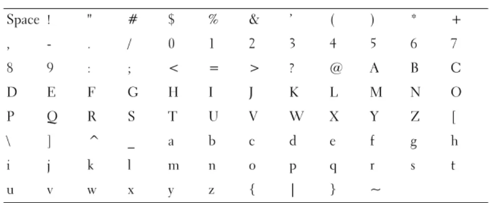
Valid Characters for CHAP Secrets
The CHAP secret must be between 12 and 57 characters. The CHAP secret supports characters with ASCII values of 32 to 126 decimal. See Table 3-1 for a list of valid ASCII characters.
Table 3-1. Valid ASCII Characters for CHAP Secrets
Space ! " # $ % & ’ ( ) * + , - . / 0 1 2 3 4 5 6 7 8 9 : ; < = > ? @ A B C D E F G H I J K L M N O P Q R S T U V W X Y Z [ \ ] ^ _ a b c d e f g h i j k l m n o p q r s t u v w x y z { | } ~
34 Using iSCSI
Changing the iSCSI Target Identification
You cannot change the iSCSI target name, but you can associate an alias with the target for simpler identification. Aliases are useful because the iSCSI target names are not intuitive. You should provide an iSCSI target alias that is meaningful and easy to remember.
1 Click the iSCSI tab, and then click Change Target Identification.
2 Type the alias in the iSCSI target alias field and click OK.
NOTE: Aliases can contain a maximum of 30 characters. Aliases can include
letters, numbers, and the special characters underscore (_), minus (-), and pound sign (#). No other special characters are permitted.
NOTE: Open iSCSI (which is used by Red Hat Enterprise Linux 5 and SUSE®
Linux Enterprise Server 10 with SP 1) does not support using target alias.
Changing the iSCSI Target Discovery (Optional)
NOTE: Changing the iSCSI Target Discovery is optional.
1 Click the iSCSI tab, and then click Change Target Discovery.
2 Select the Use iSNS server check box to activate iSCSI target discovery. You can use one of these methods:
a Use the DHCP option (IPv4 only) to automatically activate target discovery. You also can refresh the DHCP.
b Type the IPv4 or IPv6 address to activate the target discovery. After you manually enter an IP address, you also can click Advanced to set the customized TCP listening ports.
3 If you do not want to allow discovery sessions that are not named, select Disallow un-named discovery sessions.
Un-named discovery sessions are discovery sessions that are permitted to run without a target name. With an un-named discovery session, the target name or the target portal group tag is not available to enforce the iSCSI session identifier (ISID) rule. For more information on un-named discovery sessions, click the Support tab, then click View Online Help.
Configuring the MD3000i iSCSI Host Ports
Use the configuration dialog for the iSCSI host ports to set up the MD3000i iSCSI host ports to use with storage arrays in a storage area network (SAN).
1 Click the iSCSI tab, and then click Configure iSCSI Host Ports.
2 Select the controller in the iSCSI host port field, and then use one of these methods to configure the port:
a Automatically obtain the configuration using one of the following methods:
• IPv4 — Obtain the configuration from the DHCP server, or refresh DHCP.
• IPv6 — Obtain the configuration automatically from a router. b Manually specify the configuration using one of the following
methods:
• IPv4 — Enter the IP address, subnet mask, and gateway for the host port.
• IPv6 — Enter the IP address, routable IP addresses, and router IP address.
After you manually enter an IP address, you also can click Advanced to set the advanced parameters for the iSCSI target discovery.
Advanced iSCSI Host Ports Settings
NOTE: Configuring the advanced iSCSI host ports settings is optional.
Use the advanced settings for the individual iSCSI host ports to specify the TCP frame size, the virtual LAN, and the network priority.
Table 3-2. Advanced iSCSI Host Port Settings
Setting Description
Virtual LAN (VLAN) A method of creating independent logical networks within a physical network. Several VLANs can exist within a
36 Using iSCSI
NOTE: Changing any of these settings resets the iSCSI port. I/O is interrupted to
any host accessing that port. You can access the I/O automatically after the port restarts and the host logs in again.
Viewing or Ending an iSCSI Session
1 Click the iSCSI tab, and then click View/End iSCSI Sessions.
2 Select the session you want to view in the Current sessions box. The details are shown below in the Details box.
3 If you want to end the session, perform the following steps:
a Select the session that you want to end, and then click End Session to show the End Session confirmation window.
Ethernet Priority The network priority can be set from lowest to highest. Although network managers must determine these mappings, the IEEE has made broad recommendations:
•0 — lowest priority (default)
•1-4 — ranges from "loss eligible" traffic to controlled-load applications, such as streaming multimedia and business-critical traffic
•5-6 — delay-sensitive applications such as interactive video and voice
•7 — highest priority reserved for network-critical traffic (do not use with the MD3000i)
TCP Listening Port The default Transmission Control Protocol (TCP) listening port is 3260.
Jumbo Frames The maximum transmission units (MTUs). It can be set between 1500 and 9000 bytes per frame. If the Jumbo Frames are disabled, the default MTU is 1500 bytes per frame.
Table 3-2. Advanced iSCSI Host Port Settings (continued)
b In the confirmation window, type yes to confirm that you want to end the iSCSI session, and then click OK.
NOTE: If you end a session, any corresponding connections terminate the link
between the host and the storage array, and the data on the storage array is no longer available.
NOTE: When a session is manually terminated using the MD Storage
Manager, the iSCSI initiator software will automatically attempt to re-establish the terminated connection to the storage array. This may cause an error message.
4 Click Save As to save the entire iSCSI sessions topology as a text file.
Viewing iSCSI Statistics and Setting Baseline
Statistics
If the configured storage array has iSCSI technology, the View iSCSI Statistics option is available only on the iSCSI tab.
1 Click the iSCSI tab, and then click View iSCSI Statistics.
2 Select the iSCSI statistic type you want to view. Select one of these types: • Ethernet MAC statistics
• Ethernet TCP/IP statistics • Target (protocol) statistics
3 Choose either Raw statistics or the Baseline statistics.
Raw statistics are all the statistics that have been gathered since the controllers were started. Baseline statistics are point-in-time statistics that have been gathered since you set the baseline time.
After you select the statistics type and either raw or baseline statistics, the details of the statistics appear in the statistics tables.
4 To set the baseline for the statistics, complete the following steps: a Select Baseline Statistics.
38 Using iSCSI
c Confirm that you want to set the baseline statistics in the dialog that appears.
The baseline time shows the latest time you set the baseline. The sampling interval is the difference in time from when you set the baseline until you launch the dialog or click Refresh.
NOTE: You must first set a baseline before you can compare baseline
statistics.
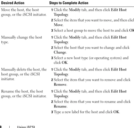
Edit, Remove, or Rename Host Topology
If you give access to the wrong host or the wrong host group, you can remove or edit the host topology. Use one of the following actions to correct the host topology:
Table 3-3. Host Topology Actions
Desired Action Steps to Complete Action Move the host, the host
group, or the iSCSI initiator.
1Click the Modify tab, and then click Edit Host Topology.
2Select the item that you want to move, and then click
Move.
3Select a host group to move the host to and click OK. Manually change the host
type.
1Click the Modify tab, and then click Edit Host Topology.
2Select the host that you want to change and click
Change.
3Select a new host type (or operating system) and clickOK.
Manually delete the host, the host group, or the iSCSI initiator.
1Click the Modify tab, and then click Edit Host Topology.
2Select the item that you want to remove and click
Remove. Rename the host, the host
group, or the iSCSI initiator.
1Click the Modify tab, and then click Edit Host Topology.
2Select the item that you want to rename and click
Rename.
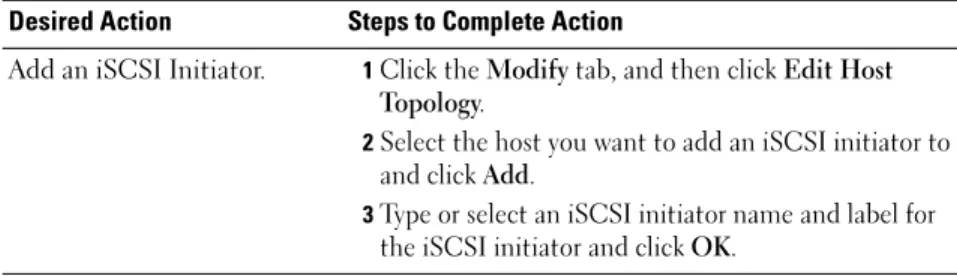
Add an iSCSI Initiator. 1Click the Modify tab, and then click Edit Host Topology.
2Select the host you want to add an iSCSI initiator to and click Add.
3Type or select an iSCSI initiator name and label for the iSCSI initiator and click OK.
Table 3-3. Host Topology Actions (continued)
Event Monitor
An event monitor is provided with MD Storage Manager. When enabled, the event monitor runs continuously in the background and monitors activity on the managed storage arrays. If the event monitor detects any critical
problems, it can notify a host or remote system using e-mail, Simple Network Management Protocol (SNMP) trap messages, or both.
For the most timely and continuous notification of events, enable the event monitor on a management station that runs 24 hours a day. Enabling the event monitor on multiple systems or having a combination of an event monitor and MD Storage Manager active can result in duplicate events, but this does not indicate multiple failures on the array.
Enabling the Event Monitor
You can enable the event monitor at any time.
NOTE: It is a good idea to configure the event monitor to start by default on a
management station that runs 24 hours a day. Microsoft® Windows®
1 Select Start → Settings → Control Panel → Administrative Tools → Services.
or
Select Start → Administrative Tools → Services.
2 From the list of services, select Modular Disk Storage Manager Event Monitor.
3 Select Action → Properties.
42 Event Monitor
Disabling the Event Monitor
Disable the event monitor if you do not want the system to send alert notifications. If you are running the event monitor on multiple systems, disabling the event monitor on all but one system prevents the sending of duplicate messages.
Windows
1 Select Start → Settings → Control Panel → Administrative Tools → Services.
or
Select Start → Administrative Tools → Services.
2 From the list of services, select Modular Disk Storage Manager Event Monitor.
3 Select Action → Properties.
4 In the Service Status area, click Stop.
Linux
At the command prompt, type SMmonitor stop and press <Enter>. When the program shutdown is complete, the system displays the following message:
About Your Host
This chapter covers basic information about configuring host groups and host access, host topology, and I/O data path protection.
A host is a system that accesses a storage array and is mapped to the virtual disks through one or more host connections. Hosts have the following attributes:
• Host name — A name that uniquely identifies the host. • Host type — The operating system running on the host.
• Host connection — A physical connection to the host server. Host connections can be automatically detected by MD Storage Manager and can be identified by an alias assigned by the user.
• Host group — A host may be associated with other hosts to share access to the same virtual disks.
Configuring Host Access
Configuring host access allows you to either permit or deny access to a storage array for specific hosts. When you permit host access, that host can then be mapped to a virtual disk on the storage array. On the Summary tab, the Hosts & Mappings area indicates how many hosts are configured to access the array. Click Configured Hosts in this area to see the names of these hosts.
Host access configuration is the first step in setting up your storage array. You must complete this task during initial setup and anytime you connect a new host.
After you configure host access, the host does not yet have the ability to write data to the storage array. You must map hosts to the virtual disks and register virtual disks with the host’s operating system before a host can write to the storage array. See “Disk Groups and Virtual Disks” on page 53 for information
44 About Your Host
To begin configuring host access, click the Configure tab and then click either Configure Host Access (Automatic) or Configure Host Access (Manual). See the appropriate section for manual configuration, depending on whether you are using SAS HBA or iSCSI.
Automatic Configuration
NOTE: The host must be connected (iSCSI or SAS) and the host agent restarted
after the connection is made in order to use automatic configuration.
To automatically configure a host for access to the storage array:
1 Click the Configure tab and then click Configure Host Access (Automatic).
2 To see hosts that already have access to the storage array, click View configured hosts.
3 Select the hosts you want to give access to the storage array in the Available hosts window.
4 To see the ports and the host type for the selected hosts, click View Details at the right of the list.
5 Click Add to move specific hosts to the Selected hosts window.
6 Click OK to configure access for the hosts you selected.
Manual Configuration (using SAS HBA)
NOTE: Host access that is manually configured requires special attention to
ensure that the correct SAS host port World Wide IDs are selected for each host. If any incorrect IDs are configured, an inaccurate topology will result. You can use the SAS/5/E HBA BIOS Setup program to identify the World Wide IDs for the SAS host ports.
Configure the host to make it available to the storage array for logical unit number (LUN) mapping by following these steps.
1 Click the Configure tab and then click Configure Host Access (Manual).
2 Type a name of your choice in the Enter host name text box.
This can be an informal name, not necessarily a name used to identify the host to the network.
3 Select the operating system of your host in the Select host type box and then click Next.
4 Specify the HBA host ports by choosing known host ports or by manually defining host ports.
To select a host port that is already recognized by MD Storage Manager, click a host port in the Known HBA host ports list, then click Add. To manually define a host port, click New, enter the HBA host port and Alias in the Enter New HBA Host Port dialog box, and then click Add.
5 Click Next.
6 Indicate whether the host is part of a host group (cluster): If the host is not part of a host group, select No.
If the host is part of a host group, select Yes:
– To create a new host group, enter a name in the Enter new host group name text box.
– To add the host to an existing host group, select the host group from the Select existing host group box.
7 Click Next.
8 Click Finish to configure the host.
Manual Configuration (using iSCSI)
Configure the host to make it available to the storage array for LUN mapping by following these steps.
1 Click the Configure tab and then click Configure Host Access (Manual).
2 Type a name of your choice in the Enter host name text box.
This can be an informal name, not necessarily a name used to identify the host to the network.
3 Select the operating system of your host in the Select host type drop-down box and then click Next.
4 Specify the iSCSI initiators by choosing known initiators or by manually defining initiators.
46 About Your Host
To manually define an initiator, click New, enter the iSCSI initiator name and iSCSI initiator label in the Enter new iSCSI initiator dialog box, and then click Add.
NOTE: The initiator name entered must match the name on a host server that
will connect to the storage array.
NOTE: In order for the host to be recognized, it must be connected with an
iSCSI session.
5 Click Next.
6 Indicate whether the host is part of a host group (cluster): If the host is not part of a host group, select No.
If the host is part of a host group, select Yes:
– To create a new host group, enter a name in the Enter new host group name text box.
– To add the host to an existing host group, select the host group from the Select existing host group box.
7 Click Next.
8 Click Finish to configure the host.
Removing Host Access
Use the following procedure to remove a host’s access to a storage array:
1 Click the Modify tab, then click Edit topology.
2 In the host topology list, click the plus sign (+) to the left of the host group name.
The host group expands to show the hosts in the group.
3 In the list, click the name of the host whose access you want to remove, and then click Remove located to the right of the list. Click Yes to remove access.
4 Repeat step 3 for each host whose access you want to remove.
5 When the list contains only those hosts you want to access the storage array, click Close beneath the list.
Host Groups
A host group is a logical entity of two or more hosts that share access to specific virtual disks on the storage array. You create host groups with MD Storage Manager.
All hosts in a host group must have the same host type (operating system). In addition, all hosts in the host group must have special software, such as clustering software, to manage virtual disk sharing and accessibility.
If a host is part of a cluster, every host in the cluster must be connected to the storage array, and every host in the cluster must be added to the host group. Use the following procedures to create a host group, to add or remove hosts from a host group, or to delete a host group.
Creating a Host Group
1 Click the Configure tab and then click Create Host Group.
2 Type a name for the new host group in the Enter new host group name text box.
3 In the Select hosts to add list, click the name of a host you want to add to the host group, then click Add.
The host moves to the Hosts in group list.
4 Repeat step 3 until all the hosts you want to add to the host group are moved into the Hosts in group list.
5 Click OK.
Adding a Host to a Host Group
1 Click the Modify tab, then click Edit Host Topology. A list of hosts and host groups appears.
2 In the host topology list, click the plus sign (+) to the left of the host group name.
48 About Your Host
4 Select the host group to which you want to move the host.
5 Click OK.
The host is moved into the host group.
The host retains the virtual disk mappings assigned to it, and inherits the virtual disk mappings assigned to the group. Other hosts in the group do not inherit the mappings of the added host.
Removing a Host From a Host Group
1 Click the Modify tab, then click Edit Host Topology. A list of hosts and host groups appears.
2 In the host topology list, click the plus sign (+) to the left of the host group name.
The host group expands to show the hosts in the group.
3 Click the name of the host you want to remove from the group.
4 Click Remove located to the right of the list.
5 Click Yes to remove the host.
The host is moved out of the host group. The host retains the virtual disk mappings assigned to it, and loses the virtual disk mappings assigned to the group.
Moving a Host to a Different Host Group
1 Click the Modify tab, then click Edit Host Topology. A list of hosts and host groups appears.
2 In the host topology list, click the plus sign (+) to the left of the host group name.
The host group expands to show the hosts in the group.
3 Click the name of the host you want to move to another group and click Move.
4 Select the host group to which you want to move the host.
5 Click OK.
The host retains the virtual disk mappings assigned to it, and inherits the virtual disk mappings assigned to the group to which it is moved. The host loses the virtual disk mappings assigned to the group from which it was moved.
Removing a Host Group
This section covers removing an entire host group. To remove a single host from a host group, see "Removing a Host From a Host Group" on page 48.
1 Click the Modify tab, then click Edit Host Topology.
2 In the host topology list, click the name of the host group you want to remove.
3 Click Remove.
4 Click Yes.
The host group and its assigned virtual disk mappings are removed.
NOTE: If the host group contains hosts, those hosts are removed as well, including
their access to the storage array.
Host Topology
Host topology is the organization of hosts, host groups, and host interfaces configured for a storage array. The Edit Host Topology screen accessed from the Modify tab shows the hierarchy of the host groups, the hosts that are part of each host group, and the host connections of each host.
You can use these tasks to change the host topology:
• Move a host or a host connection
• Rename a host group, a host, or a host connection • Add a host connection
• Replace a host connection • Change a host type
50 About Your Host
Host Context Agent
The host context agent discovers the host topology. The host context agent starts when the host is started and stops when the host is turned off. The topology discovered by the host context agent can be viewed by clicking
Configure Host Access (Automatic) in the Configure tab in the MD Storage Manager.
You must stop and restart the host context agent to see the changes to the host topology if any of the following situations occur:
• A new storage array is attached to the host server.
• A host is added while turning on power to the RAID controller modules.
Linux
In Linux, you can stop and start the host context agent from the command line. Use the following syntax: SMagent start or SMagent stop. You will stop and then restart SMagent after performing either of the two following maintenance tasks.
• Moving a controller offline or replacing a controller.
• Removing host-to-array connections from or attaching host-to-array connections to a Linux host server.
Windows
In Windows, you can stop and start the host context agent from the Services
option of the Administrative Tools. To access the host context agent:
1 Select Start → Settings → Control Panel→ Administrative Tools → Services.
or
Select Start → Administrative Tools → Services.
I/O Data Path Protection
You can have multiple host-to-array connections for a host. Make sure to select all of the connections to the array when configuring host access to the storage array.
NOTICE: Refer to the Installation Guide for more information on cabling
configurations.
NOTE: For maximum redundancy, you must select all host connections to the array
when manually defining host topology. For example, a host might have two host connections listed when manually configuring host access. For this host, you would select the two host connections listed in the "Available hosts" section and add them to the "Selected hosts" section using the Add button.
NOTE: For more information on configuring hosts see "About Your Host" on page 43.
If a component such as a RAID controller module or a cable fails, or an error occurs on the data path to the preferred RAID controller module, virtual disk ownership is moved to the alternate nonpreferred RAID controller module for processing. This failure or error is called failover.
Multi-path drivers such as MPIO and MPP are installed on host systems that access the storage array and provide I/O path failover. The multi-path driver (MPIO in Windows and MPP in Linux) is used for failover. Automatic Virtual Disk Transfer (AVT) is used specifically for single-port cluster failover. The AVT feature mode is automatically selected by host type.
NOTE: You should have the multi-path driver installed on the hosts at all times,
even in a configuration where there is only one path to the storage system, such as a single port cluster configuration.
During a failover, the virtual disk transfer is logged as a critical event, and an alert notification is sent automatically if you have configured alert
Disk Groups and Virtual Disks
Following is a list of terms used throughout this chapter:
• Disk Group — A set of physical disks that are logically grouped and assigned a RAID level. Every disk group provides the overall capacity required to create one or more virtual disks.
• Virtual Disk — A logical component created to enable hosts to access storage on the storage array. A virtual disk is created from the capacity available on a disk group and appears as one logical component even though it is created from more than one physical disk.
• Storage Partitioning — Logical division of a storage array into entities consisting of one or more virtual disks that can be accessed by a single host or shared among hosts that are part of a host group.
• Unconfigured Capacity — Physical disks that are not already assigned to a disk group.
• Free Capacity — Space in a disk group that has not been assigned to a virtual disk.
• Standby Hot Spare Drive — Physical disk that has been assigned as a hot spare drive and is available to take over for any failed physical disk.
• In-use Hot Spare Drive — Physical disk that has been assigned as a hot spare drive and is currently taking over for a failed physical disk.
• Snapshot Virtual Disk — Point-in-time image of a virtual disk in a storage array.
• Snapshot Repository Virtual Disk — Virtual disk containing metadata and copy-on-write data for a particular snapshot virtual disk; automatically created when the snapshot virtual disk is created.
• Consistency Check — Background operation that checks the parity of virtual disks.