1
Table of Contents
1. Introduction ... 2 1.1 Team Structure ... 2 1.2 Design Process ... 3 1.3 Specifications ... 32. Mechanical System Design ... 4
2.1 Chassis ... 4
2.2 Tracks ... 5
3. Electrical System Design ... 7
3.1 Power System... 7
3.2 Emergency Stop ... 8
3.3 Sensors and Actuators ... 8
4. Software System Design... 8
4.1 Software Strategy... 8
4.2 Lane Following ... 10
4.3 Obstacle Detection and Avoidance ... 10
4.4 Waypoint Navigation and Path Planning ... 11
5. Hardware ... 11
5.1 Laptop Computers... 11
5.2 Sensor Innovation - Kinect ... 12
5.3 Wiring and Cabling ... 12
5.4 Sensors ... 12
5.5 Motor Control ... 13
6. Safety, Reliability, and Performance ... 14
7. Project Cost ... 15
2
1. Introduction
For the 2012 Intelligent Ground Vehicle Competition (IGVC), team TBTTROTT presents Roy- a collaborative effort between the mechanical, electrical, computer, and software engineering departments at the Milwaukee School of Engineering (MSOE). This vehicle is the result of a nine month development cycle advised by Dr. Farrow of MSOE’s Mechanical Engineering
Department. The original design was split amongst the academic groups of the team; the main body was designed by the mechanical engineers, the power systems and battery calculations were done by the electrical engineers, sensor integration and embedded components were designed and constructed by the computer engineer, and the mapping, path finding, and sensor integration were done by the software engineers.
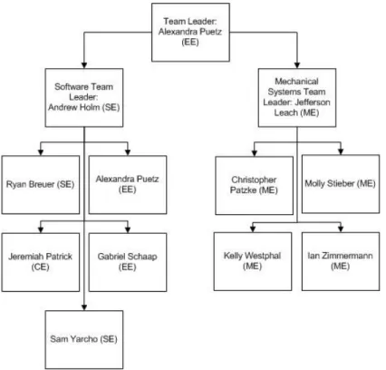
1.1 Team Structure
Team TBTTROTT consists of a Mechanical Engineering team and an Electrical Engineering and Computer Science (EECS) team; both are led by a sub-team leader which in turn reports to the team leader. The breakdown of the individuals on the team can be seen in Figure 1.
3
1.2 Design Process
Upon careful consideration of the 2012 IGVC official rules, the following design process was employed to analyze the needs and functionality of the vehicle.
Identification of Need
Definition of Problem (Specifications) Synthesis (Brainstorming)
Analysis/Optimization (Details of Design) Evaluation (Prototype)
Presentation (Meet Specifications)
The vehicle design was split into several main components: tracks, frame, power, sensor interaction, emergency stop subsystems, computer operating system, computer vision, drive control, JAUS networking subsystem, and path planning. This process was applied to all subcomponents until a final solution met their respective specifications.
1.3 Specifications
In addition to the requirements provided by the IGVC competition, the team elicited the following requirements based on the development environment.
• The vehicle must have a turning radius of at most five feet
• The vehicle’s center of gravity will be no higher than 25 inches from the ground • All fabrication must be done through campus facilities, unless donated
• Battery life must run for a minimum of 15 minutes (competition runtime) and preferably
up to 4 hours (testing runtime)
• The sensor power system and the motor power system will be isolated from each other • The vehicle should be able to identify obstacles at a minimum of 20 feet away.
4
2. Mechanical System Design
2.1 Chassis
To maintain modularity and simplicity, the frame of the vehicle was constructed of extruded t-slotted aluminum, purchased from MiSUMi. The t-t-slotted aluminum has the strength to withstand the applied loads of the components onboard as well as the impact loading experienced when the vehicle traverses rough terrain. Furthermore, after considering the modulus of elasticity of aluminum, the frame maintains its rigidity to enable turning, yet is flexible enough to absorb vibration when traversing uneven ground. The chassis was designed around the layout of the necessary electrical components to assure the sensors’ onboard location for optimum functionality. Maintaining an even distribution of weight and lowering the center of gravity were also considered to facilitate stability.
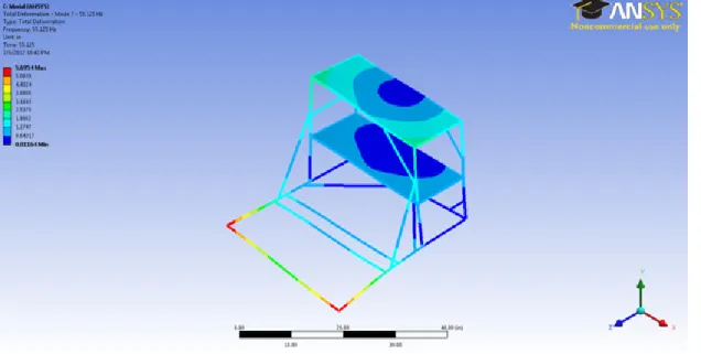
After laying out the shape and structure of the frame, a dynamic analysis was performed to verify plausibility. ANSYS Workbench was utilized to perform a modal finite element analysis (FEA) on the constructed SolidWorks CAD model of the vehicle. This analysis showed that the only dynamical concern was the front bar of the vehicle as seen in Figure 2.
This area of concern was isolated and modeled as a simple mass system t deflection in the bar under movement. Using the model fro
1 was formulated using the characteristics of the bar.
The ground input to the system, y(t) = U, was modeled using the critical frequency of the frame found from ANSYS (55 Hz) and the roughness of
From this model, MATLAB was then used to calculate the deflection in the critical bar. This was combined with the static deflection of the bar due to the weight of the batteries to obtain the maximum deflection of the front bar during operation. This value, 0.0043 inches, was deemed acceptable and the final frame design was agreed upon.
2.2 Tracks
A track system was chosen as the drive train for the
zero-point turning and the system’s inherent durability. Zero
maneuverability of the vehicle. The tracks were designed for durability as well as multiple terrains and weather conditions. This was achieved through using durable materials including carbon steel tracks, aluminum side plates, thermoplastic sprockets, and spring steel springs. Furthermore, the tracks allow the weight of the
ground during motion. Maintaining constant contact along the length of the minimize the effect of uneven terrain and enables the
solated and modeled as a simple mass system to help show the deflection in the bar under movement. Using the model from Figure 2, the differential
was formulated using the characteristics of the bar.
Figure 2: Spring Mass System
The ground input to the system, y(t) = U, was modeled using the critical frequency of the frame z) and the roughness of grassy ground (0.64 in) as shown
From this model, MATLAB was then used to calculate the deflection in the critical bar. This was combined with the static deflection of the bar due to the weight of the batteries to obtain the
on of the front bar during operation. This value, 0.0043 inches, was deemed acceptable and the final frame design was agreed upon.
track system was chosen as the drive train for the vehicle due to the capability of performing point turning and the system’s inherent durability. Zero-point turning greatly aids in the
. The tracks were designed for durability as well as multiple . This was achieved through using durable materials including carbon steel tracks, aluminum side plates, thermoplastic sprockets, and spring steel springs. Furthermore, the tracks allow the weight of the vehicle to be evenly distributed along the
ring motion. Maintaining constant contact along the length of the vehicle
minimize the effect of uneven terrain and enables the vehicle to scale any of the required 15%
5
o help show the , the differential Equation
(1) (2)
The ground input to the system, y(t) = U, was modeled using the critical frequency of the frame grassy ground (0.64 in) as shown in Equation 2. From this model, MATLAB was then used to calculate the deflection in the critical bar. This was combined with the static deflection of the bar due to the weight of the batteries to obtain the
on of the front bar during operation. This value, 0.0043 inches, was deemed
due to the capability of performing point turning greatly aids in the . The tracks were designed for durability as well as multiple
. This was achieved through using durable materials including carbon steel tracks, aluminum side plates, thermoplastic sprockets, and spring steel springs.
to be evenly distributed along the vehicle will help to to scale any of the required 15%
6
grades throughout the course. Suspension components, including spring loaded idler rollers and a spring tensioner, also aid in traversing uneven terrain or potholes while providing the
necessary tension in the system.
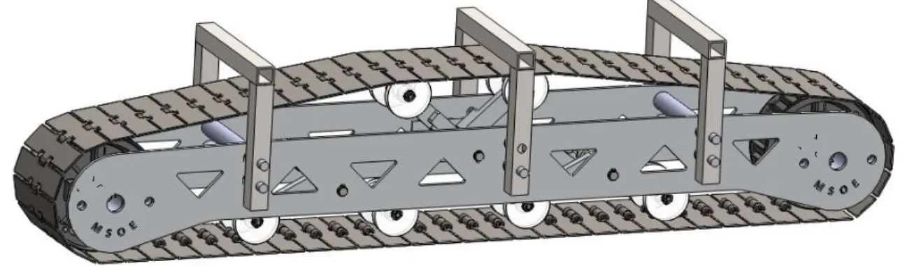
The design of the track system was not based upon any other premade track system, such as that of a tank. The tracks were designed solely for the purposes of this competition; the model is shown in figure 4. All of the tensioning and suspension assemblies contained within the tracks were custom designed and self-manufactured through campus facilities. Custom parts include the pivoting arms, nylon rollers, all axles, torsional springs, and the side plates.
Figure 4: Track Model
FEA was used as a tool throughout the many steps of the design process. The numerical stress and strain solutions produced from FEA were essential in the sizing of components such as the track side plates and idler roller arms. All three rolling shafts were sized using ASME shaft theory to ensure proper performance throughout the life of the vehicle using Equation 1.
(3) The torsional springs in the track system provided a new challenge for the team due to lack of previous experience. Static and dynamic load analysis provided the limited range and
movement characteristics of the springs. Three diameters of spring wire were chosen to physically test. This led to further refinement and allowed the final spring sets used in the track system to be determined.
7
3. Electrical System Design
3.1 Power System
Due to the potential for data corruption from electrical motor noise, the power systems of the motors and sensors are isolated from each other. Large run capacitors are used on the motors to further cut down on harmful power spikes from inrush current and stall events.
The sensor power system of Roy is based on a Milwaukee Tool 28V Lithium-Ion battery with two stages of regulation to 24V and 12V. All sensors are fused separately. The sensor battery has a rating of 1.8Ah, giving the sensors a runtime of approximately 40 minutes.
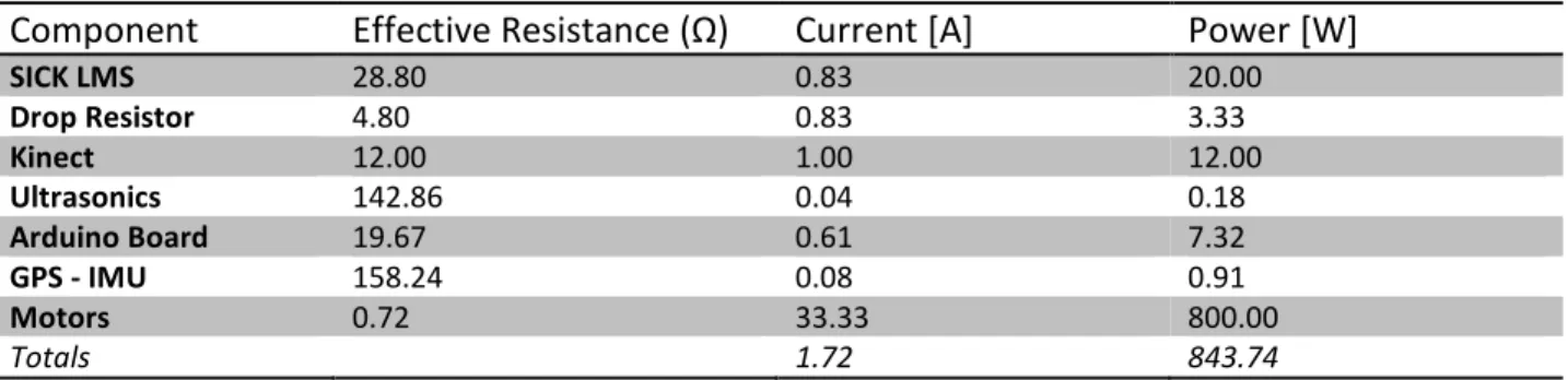
The motors are run on a 24V system of Universal Power Group sealed lead-acid batteries. The options for six or twelve batteries are available to use on the vehicle during operation, giving it a run time of approximately one half to one hour at full load. The team purchased 24 of these batteries to allow for switching battery packs to increase run time to approximately two hours. There are two types of batteries on the vehicle: sealed lead acid (SLA) batteries for the motor power supply and a Milwaukee Tool M28 Li-ion battery to power the sensor system. The emergency stop system is also powered by a separate pack of sealed lead acid batteries. Table 1 is a list of components which make up the total current and power requirements of the robot.
Table 1: Power System Requirements
Component Effective Resistance (Ω) Current [A] Power [W]
SICK LMS 28.80 0.83 20.00 Drop Resistor 4.80 0.83 3.33 Kinect 12.00 1.00 12.00 Ultrasonics 142.86 0.04 0.18 Arduino Board 19.67 0.61 7.32 GPS - IMU 158.24 0.08 0.91 Motors 0.72 33.33 800.00 Totals 1.72 843.74
8
3.2 Emergency Stop
As required by the competition, there are two emergency stop systems; wireless and manual. The wireless emergency stop is comprised of a wirelessly controlled relay and a normally open contactor (high power relay). The manual emergency stop consists of a large red button on the back of the vehicle, which is connected to the power of the wireless relay. Power disruption occurs when either the button is pushed or the wireless relay is turned off using the
transmitter. Each emergency stop system is powered by a battery pack that is completely independent from both the sensor battery and the motor batteries. Engaging the emergency stop brings the vehicle to an immediate stop.
3.3 Sensors and Actuators
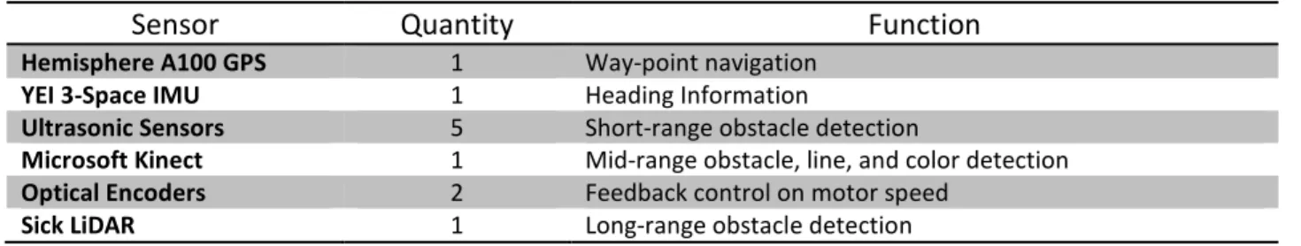
The sensor suite of the vehicle consists of the following sensors. Their quantity and function on the robot is presented in Table 1.
Table 2: Sensor Functions
Sensor Quantity Function
Hemisphere A100 GPS 1 Way-point navigation
YEI 3-Space IMU 1 Heading Information
Ultrasonic Sensors 5 Short-range obstacle detection
Microsoft Kinect 1 Mid-range obstacle, line, and color detection Optical Encoders 2 Feedback control on motor speed
Sick LiDAR 1 Long-range obstacle detection
4. Software System Design
4.1 Software Strategy
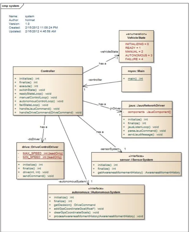
The ROYOS operating system program was created in an Ubuntu Linux environment using the C++ language. ROYOS utilizes open source robotics libraries including the Mobile Robotics Programming Toolkit (MRPT) and the Open Computer Vision library (opencv). The sensor drivers available include functions for accessing the Kinect, the SICK LiDAR, and the Hemisphere GPS. Custom drivers had to be written for the YEI 3-Space Sensor, the Drive Control interaction at the system level for the Pololu Motor Controllers, the Arduino microcontrollers, and JAUS
9
communication. The main system control group is shown as a UML diagram detailing the higher level behaviors of the main software subsystems in ROYOS in Figure 3.
Figure 3: ROYOS Main System Control Group
10
Grid and Occupancy Maps for use in path planning. In autonomous mode, the system is able to take position information from the Hemisphere GPS and YEI 3-Space Sensor in order to set the current six dimensional pose of the Kinect, SICK LiDAR, and the vehicle footprint in the localized map representation of the vehicle’s position. This map is continuously updated as observations are taken from the sensors.
4.2 Lane Following
Lane following was accomplished using an edge detection algorithm on the images read by the Kinect sensor’s primary camera. The Kinect identifies two types of data: depth and color. When it records data it takes in one data set of each type. The colored image is converted from RGB (Red Green Blue) to HSB (Hue Saturation Brightness) color space and evaluated using a thresholding function on the saturation data. This will turn all pixels white or black depending on the amount of saturation in each pixel. The image is then divided up into a grid of 5x5
“chunks” of pixels and each chunk is assigned an importance value equal to the number of black pixels (white is black in the saturation color space) located inside of each chunk. Finally, a walking algorithm is used to trace lines of significant chunks (those who have a number of black pixels above a certain threshold) to determine the location of lines. These chunks are then related to the depth data that was retrieved from the Kinect, and plotted on the obstacle map.
4.3 Obstacle Detection and Avoidance
Obstacles are observed through three sensors on the vehicle: the SICK LMS 200, the Kinect sensor’s depth map image, and the Kinect main camera, which is important for recognizing the red and blue flags which populate the course. As the observations from these sensors are taken and added to the map, a Kalman filter is applied to create increasingly more precise estimates of the probability that an obstacle exists at a given location in the map. If the obstacle is recognized as a red or green flag, it is placed in the map as a special feature, and special attention is given to the feature during the path planning algorithm. Otherwise, the obstacle is treated as impassable space when the map is interpreted as an occupancy grid for the purposes of path construction.
11
4.4 Waypoint Navigation and Path Planning
Waypoint navigation coordinates are loaded into the system from a text file containing the longitudinal and latitudinal coordinates of the point. When the command to enter autonomous mode is executed, Roy will begin the process of choosing the nearest point and attempting to navigate towards it using a modified A-Star Path Planning algorithm applied to the
interpretation of the internal map as an occupancy grid of passable space and impassable space. If no obstacles or lanes are present on the internal map representing the local area, the algorithm will construct a simple path leading directly to the point, and the vehicle will pivot towards the point and head directly at the point at the maximum speed. If obstacles or lanes are present within the locale, the algorithm will generate a series of intermediate goal points to navigate to. When the special features of a colored flag are present within the local map, the path planning algorithm will construct a path which falls between the flags.
Drive commands are sent to the drive control system as a desired linear velocity in meters per second and a desired yaw rate, or rate of turning, in radians per second. This format of
commands allows the vehicle to attempt smooth turning over paths constructed from at least three points, where the vehicle calculates a parabola that will fit the three points. The drive control system then computes the raw speed values to send to the motor control units over the serial connection.
5. Hardware
5.1 Laptop Computers
The ROYOS operating system that runs the vehicle is installed on a Hewlett Packard EliteBook 8540 Workstation laptop. This system is responsible for controlling Roy’s sensors, motor controllers, Arduino Uno boards, and network communication.
12
5.2 Sensor Innovation - Kinect
The use of the Kinect for the main camera component was an area of sensor innovation. The Mobile Robotics Programming Tool Kit (MRPT) was used, allowing the various measurements coming from the Kinect (depth and color) to tie together with the other sensors mounted on the vehicle, such as the SICK LiDAR unit and the PING))) Ultrasonic sensors.
5.3 Wiring and Cabling
All wire and cable on the ground vehicle is stranded wire to support rigorous physical abuse while in operation. Stranded wire maximizes the ability of the wire to be bent, pinched, twisted, broken, or otherwise damaged and provides a longer lifetime. Wires and cables are routed in the grooves of the aluminum T-slotted frame material or are otherwise permanently secured and routed together to minimize hanging wires. No wires or cables are left hanging or used to tether the vehicle in any way to an off-board source of power or information.
Wire gauges were selected on the basis of ampacity. Fourteen gauge wire is used for the motors, supporting a maximum current up to 32 Amps. The sensor power and communication signals system will utilize 22 gauge wires and support a maximum current of 5 Amps.
5.4 Sensors
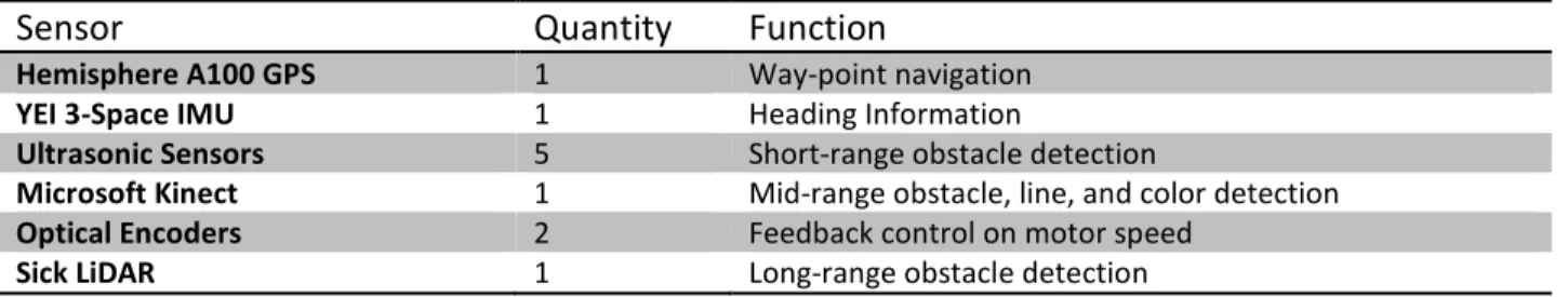
The sensor suite of the vehicle consists of the following sensors, along with their quantity and function on the vehicle.
Table 3: Sensor Functions
Sensor Quantity Function
Hemisphere A100 GPS 1 Way-point navigation
YEI 3-Space IMU 1 Heading Information
Ultrasonic Sensors 5 Short-range obstacle detection
Microsoft Kinect 1 Mid-range obstacle, line, and color detection
Optical Encoders 2 Feedback control on motor speed
13
5.5 Motor Control
The vehicle is driven by two brushed DC motors. Each motor is controlled by a Pololu Simple Motor Controller. The motor controllers give the team the ability to control the vehicle in two ways. Manual control is achieved through an RC transmitter-receiver pair linked to the motor controller, with automatic mixing for differential drive. In autonomous mode, the controllers will receive speed and direction commands directly from the operating system through a USB connection.
5.6 Arduino Board
An Arduino Uno board was used to complete a connection from the main computer to the controlling connection of the blinking light and the data collection of the ultrasonic sensors. With this board the light can be made to blink in manual and automatic mode at the command of the main computer; upon request from the main computer, ultrasonic data can be pulled from any of the attached PING))) units. The second Arduino Uno board is being used to monitor the optical encoders to utilize closed-loop control by comparing actual and desired motor speeds.
14
6. Safety, Reliability, and Performance
Critical performance measures of the vehicle were taken during testing. They were compared to the theoretical values derived during the design process.
Table 4: Specification Measurements
Measure Units Theoretical Actual
Top Speed MPH 10.0 8.0
Run Time Hours 0.5 - 1 Not Available
Incline Climb % grade 15 15
Overall Weight Lbf 325 305
Overall Size W x L x H (inches) 40 x 48 x 72 40 x 48 x 68 Center of Gravity W x L x H (inches) 20x26x16 (from RR) 20 x 22 x 16
Waypoint Navigation Accuracy Feet 1.65 Not Available
E-Stop Response Time Milliseconds 21 Not Available
Safety considerations were a top priority throughout the entirety of the project. Along with working in a safe and professional manner, several modifications have been made to the vehicle itself to ensure the safety of all involved.
Roy is equipped with both manual and wireless emergency stop systems. At any time, they can be activated to cut the power to the motors through a contactor. All circuits on the vehicle have appropriate fuses built in to avoid overloading wires or components. All batteries are totally sealed. Thus no battery acid can leak from them.
Acrylic panels will be affixed to the sides and top of the vehicle tower and above all sensors. This not only protects the sensors and electronics from damage, but also prevents short circuits that could be caused by water. The side plates on the tracks serve a safety function by keeping fingers out from the multiple pinch points that exist in the track system.
15
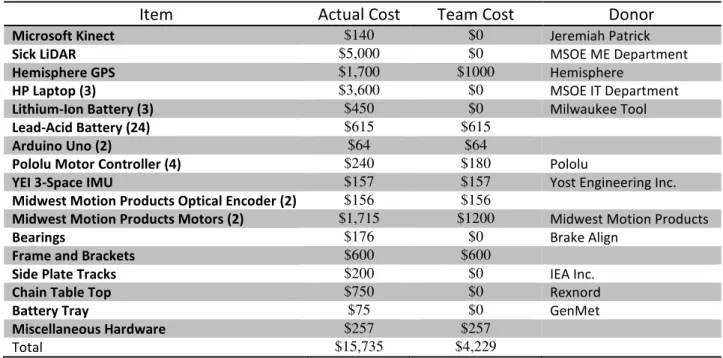
7. Project Cost
The project cost is presented in Table 4. A listing of donors for donated or discounted components is also provided.
Table 5: Project Cost and Donors
Item Actual Cost Team Cost Donor
Microsoft Kinect $140 $0 Jeremiah Patrick
Sick LiDAR $5,000 $0 MSOE ME Department
Hemisphere GPS $1,700 $1000 Hemisphere
HP Laptop (3) $3,600 $0 MSOE IT Department
Lithium-Ion Battery (3) $450 $0 Milwaukee Tool
Lead-Acid Battery (24) $615 $615
Arduino Uno (2) $64 $64
Pololu Motor Controller (4) $240 $180 Pololu
YEI 3-Space IMU $157 $157 Yost Engineering Inc.
Midwest Motion Products Optical Encoder (2) $156 $156
Midwest Motion Products Motors (2) $1,715 $1200 Midwest Motion Products
Bearings $176 $0 Brake Align
Frame and Brackets $600 $600
Side Plate Tracks $200 $0 IEA Inc.
Chain Table Top $750 $0 Rexnord
Battery Tray $75 $0 GenMet
Miscellaneous Hardware $257 $257
Total $15,735 $4,229
8. Conclusion
We are confident in our ability to meet the challenges of the Intelligent Ground Vehicle Competition. The design of Roy is robust and reliable, including the innovative design aspects such as the tracks and the use of the Kinect for line recognition. We would like to thank the ME department faculty at the Milwaukee School of Engineering, along with all of our generous sponsors. We look forward to a strong performance with our debut entrance to the 20th annual Intelligent Ground Vehicle Competition.