General rights
Copyright and moral rights for the publications made accessible in the public portal are retained by the authors and/or other copyright owners and it is a condition of accessing publications that users recognise and abide by the legal requirements associated with these rights.
Cloud RAN for Mobile Networks - a Technology Overview
Checko, Aleksandra; Christiansen, Henrik Lehrmann; Yan, Ying; Scolari, Lara; Kardaras, Georgios; Berger, Michael Stübert; Dittmann, Lars
Published in:
I E E E Communications Surveys and Tutorials DOI: 10.1109/COMST.2014.2355255 Publication date: 2014 Link to publication Citation (APA):
Checko, A., Christiansen, H. L., Yan, Y., Scolari, L., Kardaras, G., Berger, M. S., & Dittmann, L. (2014). Cloud RAN for Mobile Networks - a Technology Overview. I E E E Communications Surveys and Tutorials, 17(1), 405-426. 10.1109/COMST.2014.2355255
Cloud RAN for Mobile Networks - a Technology
Overview
Aleksandra Checko
∗†, Henrik L. Christiansen
†, Ying Yan
†,
Lara Scolari
∗, Georgios Kardaras
∗, Michael S. Berger
†and Lars Dittmann
†∗
MTI Radiocomp, Hillerød, Denmark
†
DTU Fotonik, Department of Photonics Engineering, Technical University of Denmark, Kgs. Lyngby, Denmark
Email: [email protected]
Abstract—Cloud Radio Access Network (C-RAN) is a novel
mobile network architecture which can address a number of challenges the operators face while trying to support growing end-user’s needs. The main idea behind C-RAN is to pool the Baseband Units (BBUs) from multiple base stations into centralized BBU Pool for statistical multiplexing gain, while shifting the burden to the high-speed wireline transmission of In-phase and Quadrature (IQ) data. C-RAN enables energy efficient network operation and possible cost savings on base-band resources. Furthermore, it improves network capacity by performing load balancing and cooperative processing of signals originating from several base stations. This article surveys the state-of-the-art literature on C-RAN. It can serve as a starting point for anyone willing to understand C-RAN architecture and advance the research on C-RAN.
Keywords—Cloud RAN; mobile networks; small cells; eICIC;
CoMP; Virtualization; IQ Compression; CPRI;
I. INTRODUCTION
Mobile data transmission volume is continuously rising. It is forecasted to grow 13-fold from 2012 until 2017 according to Cisco [1], with smart phones and tablet users driving the growth. Therefore, to satisfy growing user demands, mobile network operators have to increase network capacity. As spec-tral efficiency for the Long Term Evolution (LTE) standard is approaching the Shannon limit, the most prominent way to increase network capacity is by either adding more cells, creating a complex structure of Heterogeneous and Small cell Networks (HetSNets) [2] or by implementing techniques such as multiuser Multiple Input Multiple Output (MIMO) [3] as well as Massive MIMO [4], where numerous antennas simultaneously serve a number of users in the same time-frequency resource. However, this results in growing inter-cell interference levels and high costs.
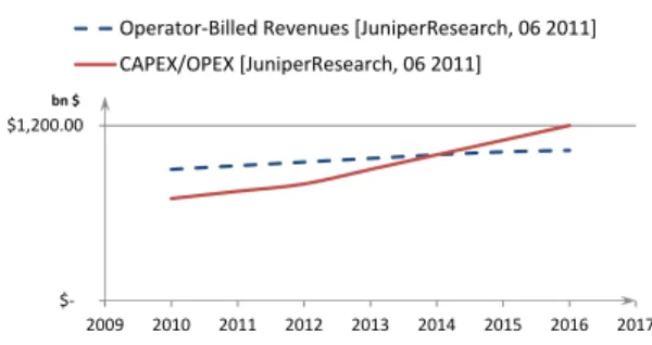
Total Cost of Ownership (TCO) in mobile networks includes CAPital EXpenditure (CAPEX) and OPerating EXpenditure (OPEX). CAPEX mainly refers to expenditure relevant to network construction which may span from network planning to site acquisition, RF hardware, baseband hardware, software licenses, leased line connections, installation, civil cost and site support, like power and cooling. OPEX covers the cost needed to operate the network, i.e., site rental, leased line, electricity, operation and maintenance as well as upgrade [5]. CAPEX and OPEX are increasing significantly when more base stations are
$1,200.00
2009 2010 2011 2012 2013 2014 2015 2016 2017 bn $
Operator-Billed Revenues [JuniperResearch, 06 2011] CAPEX/OPEX [JuniperResearch, 06 2011]
Fig. 1: Costs vs revenues in mobile networks.
deployed. More specifically, CAPEX increases as base stations are the most expensive components of a wireless network infrastructure, while OPEX increases as cell sites demand a considerable amount of power to operate, e.g., China Mobile estimates 72% of total power consumption originates from the cell sites [6]. Mobile network operators need to cover the expenses for network construction, operation, maintenance and upgrade; meanwhile, the Average Revenue Per User (ARPU) stays flat or even decreases over time, as the typical user is more and more data-hungry but expects to pay less for data usage. As presented in Figure 1 [7], mobile operators are facing cases (2014-2015) where network cost may exceed revenues if no remedial actions are taken [8]. Therefore, novel architectures that optimize cost and energy consumption become a necessity in the field of mobile network.
C-RAN is a novel mobile network architecture, which has the potential to answer the above mentioned challenges. The concept was first proposed in [9] and described in detail in [6]. In C-RAN, baseband processing is centralized and shared among sites in a virtualized BBU Pool. This means that it is able to adapt to non-uniform traffic and utilizes the resources, i.e., base stations, more efficiently. Due to that fact that fewer BBUs are needed in C-RAN compared to the traditional architecture, C-RAN has also the potential to decrease the cost of network operation, because power and energy consumption are reduced compared to the traditional RAN architecture. New BBUs can be added and upgraded easily, thereby improving scalability and easing network maintenance. Virtualized BBU Pool can be shared by different network operators, allowing
them to rent Radio Access Network (RAN) as a cloud service. As BBUs from many sites are co-located in one pool, they can interact with lower delays – therefore mechanisms introduced for LTE-Advanced (LTE-A) to increase spectral efficiency and throughput, such as enhanced ICIC (eICIC) and Coor-dinated Multi-Point (CoMP) are greatly facilitated. Methods for implementing load balancing between the cells are also facilitated. Furthermore, network performance is improved, e.g., by reducing delay during intra-BBU Pool handover.
C-RAN architecture is targeted by mobile network op-erators, as envisioned by China Mobile Research Institute [6], IBM [9], Alcatel-Lucent [10], Huawei [11], ZTE [12], Nokia Siemens Networks [5], Intel [13] and Texas Instruments [14]. Moreover, C-RAN is seen as typical realization of mobile network supporting soft and green technologies in fifth generation (5G) mobile network in year 2020 horizon [15]. However, C-RAN is not the only candidate architecture that can answer the challenges faced by mobile network operators. Other solutions include small cells, being part of HetSNets and Massive MIMO. Small cells deployments are the main competitors for outdoor hot spot as well as indoor coverage scenarios. All-in-one small footprint solutions like Alcatel-Lucent’s LightRadio can host all base station functionalities in a few liters box. They can be placed outdoors reducing cost of operation associated to cooling and cell site rental. However, they will be underutilized during low-activity periods and can not employ collaborative functionalities as well as C-RAN can do. Moreover, they are more difficult to upgrade and repair than C-RAN. Brief comparison between C-RAN, Massive MIMO and HetSNets is outlined in [2]. Liu et al. in [16] prove that energy efficiency of large scale Small Cell Networks is higher compared with Massive MIMO. Furthermore, cost evaluation on different options needs to be performed in order for a mobile network operator to choose an optimal solution. Comparison of TCO including CAPEX and OPEX over 8 years of traditional LTE macro base station, LTE C-RAN and LTE small cell shows that the total transport cost per Mbps is highest for macro cell deployment - 2200$, medium for C-RAN - 1800$ and 3 times smaller for small cell - 600$ [17]. Therefore the author concludes that C-RAN needs to achieve significant benefits to overcome such a high transportation cost. Collaborative techniques such as CoMP and eICIC can be implemented in small cells giving higher benefits in HetNet configuration instead of C-RAN. The author envisions that C-RAN might be considered for special cases like stadium coverage. However, C-RAN is attractive for operators that have free/cheap fiber resources available.
This article surveys the state-of-the-art literature published on C-RAN and its implementation. Such input helps mobile network operators to make an optimal choice on deployment strategies. The paper is organized as follows. In Section II we introduce the fundamental aspects of C-RAN architecture. Moreover, in Section III we discuss in detail the advantages of this architecture along with the challenges that need to be overcome before fully exploiting its benefits in Section IV. In Section V we also present a number of constraints in regards to the transport network capacity imposed by C-RAN and discuss possible solutions, such as the utilization of compression
schemes. In Sections VI, VII we give an overview of the state-of-the-art hardware solutions that are needed to deliver C-RAN from the radio, baseband and network sides. As the BBU Pool needs to be treated as a single entity, in Section VIII we present an overview of virtualization techniques that can be deployed inside a BBU Pool. In Section IX we evaluate possible deployment scenarios of C-RAN. In Section X we summarize ongoing work on C-RAN and give examples of first field trials and prototypes. Section XI concludes the paper.
II. WHAT ISC-RAN? BASESTATION ARCHITECTURE EVOLUTION
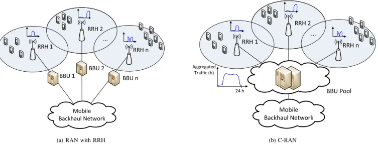
C-RAN is a network architecture where baseband resources are pooled, so that they can be shared between base stations. Figure 2 gives an overview of the overall C-RAN architecture. This section gives an introduction to base station evolution and the basis of the C-RAN concept.
The area which a mobile network covers is divided into cells, therefore mobile networks are often called cellular net-works. Traditionally, in cellular networks, users communicate with a base station that serves the cell under coverage of which they are located. The main functions of a base station can be divided into baseband processing and radio functionalities. The main sub-functions of baseband processing module are shown in left side of Figure 3. Among those we find coding, modulation, Fast Fourier Transform (FFT), etc. The radio module is responsible for digital processing, frequency filtering and power amplification.
A. Traditional architecture
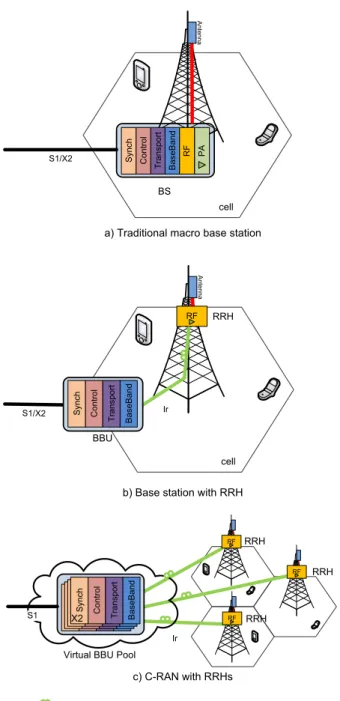
In the traditional architecture, radio and baseband processing functionality is integrated inside a base station. The antenna module is generally located in the proximity (few meters) of the radio module as shown in Figure 4a as coaxial cables employed to connect them exhibit high losses. X2 interface is defined between base stations, S1 interface connects a base station with mobile core network. This architecture was popular for 1G and 2G mobile networks deployment. B. Base station with RRH
In a base station with Remote Radio Head (RRH) archi-tecture, the base station is separated into a radio unit and a signal processing unit, as shown in Figure 4b. The radio unit is called a RRH or Remote Radio Unit (RRU). RRH provides the interface to the fiber and performs digital processing, digital to analog conversion, analog to digital conversion, power amplification and filtering [18]. The baseband signal processing part is called a BBU or Data Unit (DU). More about BBU can be found in Chapter 16 of [19]. Interconnection and function split between BBU and RRH are depicted in Figure 3. This architecture was introduced when 3G networks were being deployed and right now the majority of base stations use it.
The distance between a RRH and a BBU can be extended up to 40 km, where the limitation is coming from processing and propagation delay. Optical fiber and microwave connections
RRH 1 RRH 2 RRH n ... Mobile Backhaul Network BBU 2 BBU n BBU 1
(a) RAN with RRH
Cloud RRH 1 RRH 2 RRH n ... BBU Pool Mobile Backhaul Network Aggregated Traffic (h) 24 h (b) C-RAN
Fig. 2: Statistical multiplexing gain in C-RAN architecture for mobile networks.
C o n tr o l-R R C Tr an sp o rt -M A C L3 L2 C o M P eI C IC C h an n el d e-/ co d in g D e-/Q u an ti za ti o n A n te n n a M ap p in g-M IM O D e-/S am p lin g R es o u rc e-b lo ck M ap p in g D e-/M o d u la ti o n IF FT /F FT ... ... ... ... IQ DL IQ UL CPRI/ OBSAI /ORI CFR / DPD DAC ADC Frequ ency filter BBU RRH
RRC Radio Resource Control SRC Sampling Rate Conversion DAC Digital-to-Analog Converter
MAC Media Access Control DUC/DDC Digital Up/Downconversion ADC Analog-to-Digital Converter
FFT Fast Fourier Transform CFR Crest Factor Reduction Power Amplifier
DPD Digital Predistortion C P R I/ O B SA I/ O R I L1 S R C D U C S R C D D C
Fig. 3: Base station functionalities. Exemplary baseband processing functionalities inside BBU are presented for LTE implementation. Connection to RF part and sub modules of RRH are shown.
can be used. In this architecture, the BBU equipment can be placed in a more convenient, easily accessible place, enabling cost savings on site rental and maintenance compared to the traditional RAN architecture, where a BBU needs to be placed close to the antenna. RRHs can be placed up on poles or rooftops, leveraging efficient cooling and saving on air-conditioning in BBU housing. RRHs are statically assigned to BBUs similarly to the traditional RAN. One BBU can serve many RRHs. RRHs can be connected to each other in a so called daisy chained architecture. An Ir interface is defined, which connects RRH and BBU.
Common Public Radio Interface (CPRI) [20] is the radio in-terface protocol widely used for IQ data transmission between RRHs and BBUs - on Ir interface. It is a constant bit rate, bidirectional protocol that requires accurate synchronization and strict latency control. Other protocols that can be used are Open Base Station Architecture Initiative (OBSAI) [21] and
Open Radio equipment Interface (ORI) [22], [23]. C. Centralized base station architecture - C-RAN
In C-RAN, in order to optimize BBU utilization between heavily and lightly loaded base stations, the BBUs are cen-tralized into one entity that is called a BBU/DU Pool/Hotel. A BBU Pool is shared between cell sites and virtualized as shown in Figure 4c. A BBU Pool is a virtualized cluster which can consist of general purpose processors to perform baseband (PHY/MAC) processing. X2 interface in a new form, often referred to as X2+ organizes inter-cluster communication.
The concept of C-RAN was first introduced by IBM [9] under the name Wireless Network Cloud (WNC) and builds on the concept of Distributed Wireless Communication System [24]. In [24] Zhouet al.propose a mobile network architecture in which a user communicates with densely placed distributed antennas and the signal is processed by Distributed Processing
B
as
eB
an
d
a) Traditional macro base station
A
nte
nn
a
b) Base station with RRH
RF
RF
c) C-RAN with RRHs Virtual BBU Pool
RRH RRH
RRH
RF
Fiber – Digital BaseBand Coax cable – RF BS cell T ra ns po rt C on tr ol S yn ch B as eB an d S yn ch C on tr ol T ra ns po rt B as eB an d S yn ch C on tr ol T ra ns po rt B as eB an d S yn ch C on tr ol T ra ns po rt B as eB an d T ra ns po rt C on tr ol S yn ch S1/X2 R F P A A nte nn a cell S1/X2 RRH RF BBU B as eB an d T ra ns po rt C on tr ol S yn ch Ir Ir S1 X2
Fig. 4: Base station architecture evolution.
Centers (DPCs). C-RAN is the term used now to describe this architecture, where the letter C can be interpreted as: Cloud, Centralized processing, Cooperative radio, Collaborative or Clean.
Figure 5 shows an example of a C-RAN mobile LTE network. The fronthaul part of the network spans from the RRHs sites to the BBU Pool. The backhaul connects the BBU Pool with the mobile core network. At a remote site, RRHs are co-located with the antennas. RRHs are connected to the high
EPC Base band Base band Base band Base band S1 S1 X2 BBU pool Access network MME SGW PGW Fronthaul Backhaul Base band Base band Base band Base band BBU pool Aggregation network Mobile Core Network RRH RRH RRH RRH RRH Ir
Fig. 5: C-RAN LTE mobile network.
performance processors in the BBU Pool through low latency, high bandwidth optical transport links. Digital baseband, i.e., IQ samples, are sent between a RRH and a BBU.
Table I compares traditional base station, base station with RRH and base station in C-RAN architecture.
TABLE I: Comparison between traditional base station, base station with RRH and C-RAN
Architecture Radio and baseband functionalities Problem it addresses Problems it causes Traditional base station Co-located in one unit
- High power con-sumption Resources are un-derutilized Base station with RRH Spitted between RRH and BBU. RRH is placed to-gether with antenna at the remote site. BBU located within 20-40 km away. Generally deployed nowadays
Lower power con-sumption. More convenient placement of BBU
Resources are un-derutilized
C-RAN Spitted into RRH and BBU. RRH is placed to-gether with antenna at the remote site. BBUs from many sites are co-located in the pool within 20-40 km away. Possibly deployed in the future
Even lower power consumption. Lower number of BBUs needed -cost reduction Considerable transport resources between RRH and BBU
III. ADVANTAGES OFC-RAN
Both macro and small cell can benefit from C-RAN ar-chitecture. For macro base station deployments, a centralized BBU Pool enables an efficient utilization of BBUs and reduces the cost of base stations deployment and operation. It also reduces power consumption and provides increased flexibility in network upgrades and adaptability to non-uniform traffic. Furthermore, advanced features of LTE-A, such as CoMP and interference mitigation, can be efficiently supported by C-RAN, which is essential especially for small cells deploy-ments. Last but not least, having high computational processing power shared by many users placed closer to them, mobile
0 5 10 15 20 25 30 35 40 45 0 6 12 18 24 Loa d Time (h)
Office base station [6] Residential base station [6]
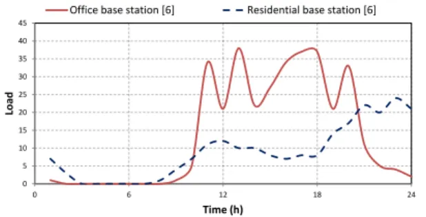
Fig. 6: Daily load on base stations varies depending on base station location.
operators can offer users more attractive Service Level Agree-ments (SLAs), as the response time of application servers is noticeably shorter if data is cached in BBU Pool [25]. Network operators can partner with third-party service developers to host servers for applications, locating them in the cloud - in the BBU Pool [26]. In this section we describe and motivate advantages of C-RAN: A. Adaptability to nonuniform traffic and scalability, B. Energy and cost savings, C. Increase of throughput, decrease of delays as well as D. Ease in network upgrades and maintenance.
A. Adaptability to nonuniform traffic and scalability
Typically, during a day, users are moving between different areas, e.g., residential and office. Figure 6 illustrates how the network load varies throughout the day. Base stations are often dimensioned for busy hours, which means that when users move from office to residential areas, the huge amount of processing power is wasted in the areas from which the users have moved. Peak traffic load can be even 10 times higher than during off-the-peak hours [6]. In each cell, daily traffic distribution varies, and the peaks of traffic occur at different hours. Since in C-RAN baseband processing of multiple cells is carried out in the centralized BBU pool, the overall utiliza-tion rate can be improved. The required baseband processing capacity of the pool is expected to be smaller than the sum of capacities of single base stations. The ratio of sum of single base stations capacity to the capacity required in the pool is called statistical multiplexing gain.
In [27] an analysis on statistical multiplexing gain is per-formed as a function of cell layout. The analysis shows that in the Tokyo metropolitan area, the number of BBUs can be reduced by 75% compared to the traditional RAN architecture. In [28] Madhavanet al.quantify the multiplexing gain of con-solidating WiMAX base stations in different traffic conditions. The gain increases linearly with network size and it is higher when base stations are experiencing higher traffic intensity. In our previous work [29] we present initial evaluation of statistical multiplexing gain of BBUs in C-RAN. The paper concludes that 4 times less BBUs are needed for user data processing in a C-RAN compared to a traditional RAN for
specific traffic patterns, making assumptions of the number of base stations serving different types of areas. The model does not include mobile standard protocols processing. After including protocol processing in [30] we concluded that the statistical multiplexing gain varies between 1.2 and 1.6 de-pending on traffic mix, thereby enabling saving of 17% - 38%. In [31] Bhaumik et al. show that the centralized architecture can potentially result in savings of at least 22% in compute resources by exploiting the variations in the processing load across base stations. Results have been evaluated experimen-tally. In [32] Werthmann et al. prove that the data traffic influences the variance of the compute resource utilization, which in consequence leads to significant multiplexing gains if multiple sectors are aggregated into one single cloud base station. Aggregation of 57 sectors in a single BBU Pool saves more than 25% of the compute resources. Moreover, the user distribution has a strong influence on the utilization of the compute resources. The results of last three works converge giving around 25% of potential savings on baseband resources. Statistical multiplexing gain can be maximized by employ-ing a flexible, reconfigurable mappemploy-ing between RRH and BBU adjusting to different traffic profiles [33]. Statistical multiplexing gain depends on the traffic, therefore it can be maximized by connecting RRHs with particular traffic profiles to different BBU Pools [30].
Coverage upgrades simply require the connection of new RRHs to the already existing BBU Pool. To enhance network capacity, existing cells can then be split, or additional RRHs can be added to the BBU Pool, which increases network flexibility. Deployment of new cells is in general more easily accepted by local communities, as only a small device needs to be installed on site (RRH) and not a bulky base station. If the overall network capacity shall be increased, this can be easily achieved by upgrading the BBU Pool, either by adding more hardware or exchanging existing BBUs with more powerful ones.
As BBUs from a large area will be co-located in the same BBU Pool, load balancing features can be enabled with advanced algorithms on both the BBU side and the cells side. On the BBU side, BBUs already form one entity, therefore load balancing is a matter of assigning proper BBU resources within a pool. On the cells side, users can be switched between cells without constraints if the BBU Pool has capacity to support them, as capacity can be assigned dynamically from the pool. B. Energy and cost savings coming from statistical multiplex-ing gain in BBU Pool
By deploying C-RAN, energy, and as a consequence, cost savings, can be achieved [34]. 80% of the CAPEX is spent on RAN [6], therefore it is important to work towards reducing it.
Energy in mobile network is spent on power amplifiers, supplying RRH and BBU with power and air conditioning. 41% of OPEX on a cell site is spent on electricity [6]. Employing C-RAN offers potential reduction of electricity cost, as the number of BBUs in a C-RAN is reduced compared to a traditional RAN. Moreover, in the lower traffic period,
e.g. during the night, some BBUs in the pool can be switched off not affecting overall network coverage. Another important factor is the decrease of cooling resources, which takes 46% of cell site power consumption [6]. Due to the usage of RRHs air conditioning of radio module can be decreased as RRHs are naturally cooled by air hanging on masts or building walls, as depicted in Figure 4. ZTE estimates that C-RAN enables 67%-80% power savings compared with traditional RAN architecture, depending on how many cells one BBU Pool covers [12], which stays in line with China Mobile research claiming 71% power savings [35].
Civil work on remote sites can be reduced by gathering equipment in a central room, what contributes to additional OPEX savings.
In total, 15% CAPEX and 50% OPEX savings are en-visioned comparing to RAN with RRH [35] or traditional RAN architecture [36]. However, the cost of leasing the fiber connection to the site may increase CAPEX. IQ signal transported between RRHs and BBUs brings up a significant overhead. Consequently, the installation and operation of trans-port network causes considerable costs for operators.
C. Increase of throughput, decrease of delays
The next generation mobile network, envisaged to even-tually replace the 3G networks is called LTE and has been standardized by Third Generation Partnership Project (3GPP) (in Release 8 and onwards of the standards). See [37] for a comprehensive overview. LTE-A is the latest mobile network standard prepared by the 3GPP in Release 10 - 12 of the standards. Any mobile network standard could potentially be deployed in a C-RAN architecture. However, as LTE is currently deployed all over the world, LTE and LTE-A are the most prominent standards to be deployed as C-RANs. This section introduces LTE radio access scheme and mechanisms proposed for LTE-A - eICIC and CoMP. Because of pooling of BBU resources in a C-RAN, those features are greatly facilitated, as signal processing from many cells can be done over one BBU Pool, easing the implementation and reducing processing and transmitting delays. Good understanding of eICIC and CoMP helps to conclude about the opportunities that C-RAN offers.
LTE operates with shared resources only. There is a sched-uler in the base station (called evolved Node B (eNB) in LTE) that takes care of all resource allocation/assignments. A key feature in LTE is the radio access scheme based on Orthogonal Frequency-Division Multiple Access (OFDMA). The basic idea in OFDMA is to use a large number of densely spaced, orthogonal carriers. Resources can be dynamically allocated both in the frequency and time domain. This gives a very flexible utilization of the available resources.
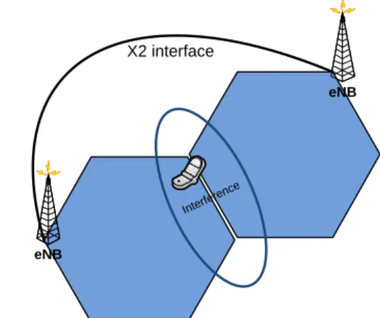
LTE systems generally use a frequency reuse factor of 1, meaning that all cells operate at the same frequency. Hence, inter-cell interference is particularly high in such systems. This is observed as a very high ratio (up to a factor of 10) between peak throughput and cell edge throughput.
Basically, there are two approaches to address the interfer-ence issue: minimizing interferinterfer-ence and exploiting interferinterfer-ence paths constructively.
eNB
eNB
Interfere nce
X2 interface
Fig. 7: Interference handling in LTE network.
1) Minimizing inter cell interference: Inter cell interference can be avoided either statically or dynamically in time, fre-quency and power domain. An obvious, static solution is not to use co-channel deployment, i.e., simply by using different frequencies in adjacent cells. This is called hard frequency reuse, and has the advantage that it avoids X2 signaling almost entirely. Fractional frequency reuse can also be used (static and dynamic approaches are commonly used, see e.g., [38]). However, as the frequency resources on lower bands are scarce it is better to use other solutions rather than the ones involving frequency reuse. Therefore, this section focuses on the case where the same frequency resources are being used in all cells. In Release 8, Inter-cell Interference Coordination (ICIC) was introduced. In this scheme UEs can report back to the eNB in case they experience strong interference on certain sub-carriers. The eNB can then (by using the X2 interface) coordinate with the neighboring cell so that these sub-carriers are not used for that particular mobile, as shown in Figure 7. It is important to note here, that this is applied to cell-edge mobiles only. Near the center of the cell there is no interference and the full resource (i.e., entire frequency band) set can be utilized.
The scheme works in uplink (UL) as well as downlink (DL). In DL the eNBs can exchange the so called RNTPs (Relative Narrowband Transmit Power) which is a bitmap containing information on the transmit power on each RB. In the UL there are reactive, using OI (Overload Indicators) and proactive, using HII (High Interference Indicators) methods. For a detailed description see e.g., chapter 12 in [39].
This solution is relatively simple and requires no synchro-nization of eNBs, only load and scheduling information need to be exchanged. The disadvantage is that the scheduler operating in each eNB can make less optimal scheduling decisions if it has to take neighbor cell interference into account. Moreover, the control channels still interfere, as they are sent on fixed resources. This scheme is slow enough to operate seamlessly on networks with a distributed base station architecture.
In Release 10 eICIC was introduced. eICIC exploits the time domain by introducing ABS (Almost Blank Sub-frames) meaning that particular sub-frames are muted. (In fact they are
not muted completely. To make them backwards compatible with Release 8, some signals, e.g., CRS (Common Reference Signal) is still being transmitted, hence the name almost blank). If one transmission is muted, there will be (almost) no interference and this interference-free time interval can now be used to send important information, e.g., signaling and reference signals. The actual muting pattern to use is being coordinated between the eNBs by using the X2 interface. The eICIC concept is standardized, but the actual muting patterns and the algorithms to select them are not.
The power domain can also be exploited to alleviate inter-ference problems. These methods are applicable primarily in the UL direction in HetNet scenarios. The concept is simply to dynamically control the transmit power of the mobile station and in this manner manage interference between the pico and macro layer.
2) Utilizing interference paths constructively: The most advanced way of dealing with inter-cell interference is called CoMP, which relies on the fundamental idea to turn inter-ference into a useful signal. This increases the Signal to Interference plus Noise Ratio (SINR) at the mobile, which again turns into higher achievable bit rates. It is included in Release 11 of the specifications [40], [41], [42].
With CoMP several cells, grouped in a so-called CoMP-set, cooperate on serving one user or a group of users, based on feedback from the mobile(s). Especially in DL this requires tight synchronization and coordination among the base stations in a CoMP set.
The simplest CoMP implementation can be seen as an extension of ICIC. Here one mobile only receives transmission from one eNB (called the serving cell) while the remaining eNBs in the CoMP set aid in avoiding interference. They do that by not using particular sub-carriers (CS - Coordinated Scheduling) and/or utilizing special, e.g., beamforming, an-tennas (CB - Coordinated Beamforming). Thus, the gain here is that all cells in the CoMP set jointly decide on how to do scheduling and beamforming in order to minimize interference for all users. CS/CB requires base station synchronization (0.05 ppm frequency and 3µ s timing accuracy) similar to ordinary LTE system operation, as only one base station is actively transmitting to one user at a time.
An expansion of CS/CB is called Dynamic Cell Selection (DCS). In this case the data to be transmitted to a particular mobile is made available to all cells in a CoMP set. At a given point of time still only one eNB transmits to a mobile, but the cells coordinate which should do the actual transmission. This is advantageous as transmission can now be done from the eNB which has most favorable transmission path to the mobile. This scheme requires base station synchronization at the same level as CS/CB.
Joint Transmission (JT) [43], [42] is the most advanced CoMP scenario. In JT the data to be transmitted is also available to all cells in the CoMP set, but in this case, several cells jointly and coherently transmit to one user. It relies on very timely and accurate feedback from the terminal on the property of the combined channel from several base stations. In order to achieve this, a new set of CSI (Channel State Informa-tion) reference signal was developed and incorporated into the
standards. In single user JT, several cells simply send the same information to one user. Therefore, instead of muting resources (as in ICIC), the same information is transmitted with exact timing to allow the signals to be combined coherently at the receiver and thus achieving a SINR gain. The disadvantage is of course that this takes up resources in several cells and thus effectively creates a reuse factor 1/3 system. This means that it is most suitable for lightly loaded systems. Single user JT can be combined with DCS, meaning that the CoMP set is dynamically changing. For heavily loaded systems JT can be expanded to multiuser JT, where groups of users are sharing (time-frequency) resources. This is, in essence, a combination of multi user MIMO and JT. This scheme requires tight base station synchronization (0.02 ppm frequency and0.5µs timing accuracy) and it is thus beneficial to use in centralized (i.e., C-RAN) based network architectures.
From a performance point of view it turns out that DCS is the best scheme in case of 2x2 MIMO operation. Four transmit antennas are needed in order to take advantage of more elaborate schemes such as JT.
If all the cells within a CoMP set are served by one BBU Pool, then a single entity doing signal processing enables tighter interaction between base stations. Therefore interfer-ence can be kept to lower level and consequently the through-put can be increased [34]. It has been proven that combining clustering of cells with CoMP makes more efficient use of the radio bandwidth [44]. Moreover, ICIC can be implemented over a central unit - BBU Pool - optimizing transmission from many cells to multiple BBUs [43].
In [45] Huiyu et al. discuss the factors affecting the per-formance of CoMP with LTE-A in C-RAN UL, i.e., receiver algorithm, reference signals orthogonality and channel estima-tion, density and size of the network. In [6] authors present simulation results which compare spectrum efficiency of intra-cell and inter-intra-cell JT to non-cooperative transmission. 13% and 20% increase in spectrum efficiency was observed, respec-tively. For a cell edge user, spectrum efficiency can increase by 75% and 119%, respectively. In [46] Li et al. introduce LTE UL CoMP joint processing and verify its operation on a C-RAN test bed around Ericsson offices in Beijing Significant gain was achieved at the cell edge both for intra-site CoMP and inter-site CoMP. Throughput gain is 30-50% when there is no interference and can reach 150% when interference is present. The authors have compared MRC (Maximum Ratio Combining) and full IRC (Interference Rejection Combining). Due to the reduction of X2 usage in C-RAN, real time CoMP can give 10-15% of joint processing gain, while real time ICIC enables 10-30% of multi cell Radio Resource Management (RRM) gain [5]. Performance of multiple-point JT and multiple-user joint scheduling has been analyzed for a non-ideal channel with carrier frequency offset [47]. When carrier frequency offset does not exceed ±3 ∼5ppb, C-RAN can achieve remarkable performance gain on both capacity and coverage even in non-ideal channel, i.e., 20%/52% for cell average/cell edge.
With the introduction of the BBU Pool cooperative tech-niques, as Multi-Cell MIMO [48] can be enhanced. This can be achieved due to tighter cooperation between base station within
a pool. In [49], Liuet al.present a downlink Antenna Selection Optimization scheme for MIMO based on C-RAN that showed advantages over traditional antenna selection schemes.
3) Decrease of the delays: The time needed to perform handovers is reduced as it can be done inside the BBU Pool instead of between eNBs. In [50] Liu et al. evaluate the improvement on handover performance in C-RAN and compare it with RAN with RRHs. In Global System for Mobile Communications (GSM), the total average handover interrupt time is lower and the signaling is reduced due to better synchronization of BBUs. In Universal Mobile Telecommuni-cations System (UMTS) signaling, Iub transport bearer setup and transport bandwidth requirements are reduced, however, the performance improvement may not be sensed by the user. For LTE X2-based inter-eNB handover the delay and failure rate are decreased. Moreover, the general amount of signaling information sent to core mobile network is reduced, after being aggregated in the pool.
D. Ease in network upgrades and maintenance
C-RAN architecture with several co-located BBUs eases network maintenance: not only C-RAN capacity peaks and failure might be absorbed by BBU Pool automatic reconfigu-ration, therefore limiting the need for human intervention, but whenever hardware failures and upgrades are really required, human intervention is to be done only in a very few BBU pool locations. On the contrary for traditional RAN, the servicing may be required at as many cell sites as there are in the network. C-RAN with a virtualized BBU Pool gives a smooth way for introducing new standards, as hardware needs to be placed in few centralized locations. Therefore deploying it can be considered by operators as a part of their migration strategy. Co-locating BBUs in BBU Pool enables more frequent CPU updates than in case when BBUs are located in remote sites. It is therefore possible to benefit from the IT technology im-provements in CPU technology, be it frequency clock (Moores law) or energy efficiency (as currently seen in Intel mobile processor road map or ARM architecture).
Software Defined Radio (SDR) is a well known technology that facilitates implementation in software of such radio func-tions like modulation/demodulation, signal generation, coding and link-layer protocols. The radio system can be designed to support multiple standards [51]. A possible framework for implementing software base stations that are remotely programmable, upgradable and optimizable is presented in [52]. With such technology, C-RAN BBU Pool can support multi-standard multi-system radio communications configured in software. Upgrades to new frequencies and new standards can be done through software updates rather than hardware upgrades as it is often done today on non-compatible vertical solutions. Multi-mode base station is therefore expected to alleviate the cost of network development and Operations, Administration and Maintenance (OAM).
IV. CHALLENGES OFC-RAN
Before the commercial deployment of C-RAN architectures a number of challenges need to be addressed: A. High band-width, strict latency and jitter as well as low cost transport
Fronthaul transport network Section V Base band Base band Base band Base band BBU pool RRH RRH RRH Virtualization Section VIII Section VI BBU Implementation Section VII
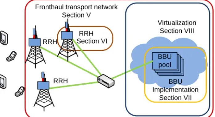
Fig. 8: An overview on technical solutions addressed in this paper.
network needs to be available, B. Techniques on BBU coop-eration, interconnection and clustering need to be developed as well as C. Virtualization techniques for BBU Pool need to be proposed. In this section we elaborate on those challenges. In the latter sections we present an ongoing work on pos-sible technical solutions that enable C-RAN implementation (Section V, VI, VII and VIII). Figure 8 gives an overview of technical solutions addressed in the article.
A. A need for high bandwidth, strict latency and jitter as well as low cost transport network
C-RAN architecture brings a huge overhead on the optical links between RRH and BBU Pool. Comparing with backhaul requirements, the one on fronthaul are envisioned to be 50 times higher [43].
IQ data is sent between BBU and RRH as shown in Figure 3. The main contributors to the size of IQ data are: turbocoding (e.g., in UMTS and LTE 1:3 turobocode is used resulting in three times overhead), chosen radio interface (e.g., CPRI) IQ sample width and oversampling of LTE signal. For example, 30.72 MHz sampling frequency is standardized for 20 MHz LTE, which is more than 20 MHz needed according to Nyquist - Shannon sampling theorem. Total bandwidth depends also on number of sectors and MIMO configuration. Equation 1 summarizes factors that influence IQ bandwidth. Scenario of 20 MHz LTE, 15+1 CPRI IQ Sample width, 10/8 line coding, 2x2 MIMO transmission resulting in 2.5 Gbps bit rate in fronthal link is often treated as a baseline scenario. Consequently, for 20 MHz 4x4 MIMO, 3 sector base station, the expected IQ throughput exceeds 10 Gbps. Examples on expected IQ bit rate between cell site and BBU in LTE-A, LTE, Time Division Synchronous Code Division Multiple Access (TD-SCDMA) and GSM networks can be found in Table II. The centralized BBU Pool should support 10 - 1000 base station sites [6], therefore a vast amount of data needs to be carried towards it.
IQBandwidth=samplingF requency·sampleW idth
TABLE II: IQ bit rates between a cell site and centralized BBU Pool
Cell configuration Bit rate Source 20 MHz LTE, 15+1 CPRI IQ Sample width, 10/8
line coding, 2x2 MIMO
2.5 Gbps
5x20 MHz LTE-A, 15 CPRI IQ Sample width, 2x2 MIMO, 3 sectors
13.8 Gbps [53] 20 MHz LTE, 4x2 MIMO, 3 sectors 16.6 Gbps [10] TD-LTE, 3 sectors 30 Gbps [54] 1.6 MHz TD-SCDMA, 8Tx/8Rx antennas, 4 times
sampling rate 330 Mbps [6] TD-SCDMA S444, 3 sectors 6 Gbps [54] 200 kHz GSM, 2Tx/2Rx antennas, 4x sampling rate 25.6 Mbps [6]
The transport network not only needs to support high bandwidth and be cost efficient, but also needs to support strict latency and jitter requirements. Below different constraints on delay and jitter are summarized:
1) The most advanced CoMP scheme, JT, introduced in section III-C requires 0.5µs timing accuracy in col-laboration between base stations, which is the tightest constraint. However, it is easier to cope with synchro-nization challenges in C-RAN compared to traditional RAN due to the fact that BBUs are co-located in the BBU Pool.
2) According to [6], regardless of the delay caused by the cable length, round trip delay of user data may not exceed 5µs, measured with the accuracy of±16.276ns
on each link or hop [20].
3) The sub-frame processing delay on a link between RRHs and BBU should be kept below 1 ms, in order to meet HARQ requirements. Due to the delay re-quirements of HARQ mechanism, generally maximum distance between RRH and BBU must not exceed 20-40 km [6].
Recommendations on transport network capacity can be found in section V.
B. BBU cooperation, interconnection and clustering
Cooperation between base stations is needed to support CoMP in terms of sharing the user data, scheduling at the base station and handling channel feedback information to deal with interference.
Co-location of many BBUs requires special security and resilience mechanisms. Solutions enabling connection of BBUs shall be reliable, support high bandwidth and low latency, low cost with a flexible topology interconnecting RRHs. Thus, C-RAN must provide a reliability that is better or comparable to traditional optical networks like Synchronous Digital Hier-archy (SDH), which achieved high reliability due to their ring topology. Mechanisms like fiber ring network protection can be used.
Cells should be optimally clustered to be assigned to one BBU Pool, in order to achieve statistical multiplexing gain, facilitate CoMP, but also to prevent the BBU Pool and the transport network from overloading. One BBU Pool should
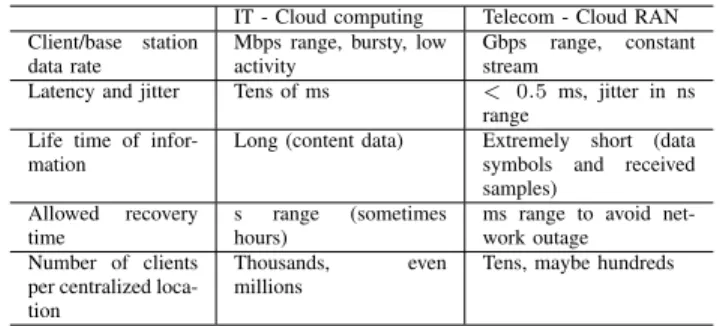
TABLE III: Requirements for cloud computing and C-RAN applications [43]
IT - Cloud computing Telecom - Cloud RAN Client/base station
data rate
Mbps range, bursty, low activity
Gbps range, constant stream
Latency and jitter Tens of ms < 0.5 ms, jitter in ns range
Life time of infor-mation
Long (content data) Extremely short (data symbols and received samples)
Allowed recovery time
s range (sometimes hours)
ms range to avoid net-work outage
Number of clients per centralized loca-tion
Thousands, even millions
Tens, maybe hundreds
support cells from different areas such as office, residential or commercial. After analyzing interferences a beneficial assign-ment of cells to one BBU Pool can be chosen.
To achieve optimal energy savings of the C-RAN, base stations need to be chosen in a way that will optimize the number of active RRHs/BBU units within the BBU Pool. Proper RRH aggregation and assignment to one BBU Pool can also facilitate CoMP [44].
To achieve optimal throughput on the cell edges cooperative transmission/reception schemes are needed to deal with large Inter Cell Interference (ICI), improving spectrum efficiency. The resource sharing algorithms have been developed by the research community. They need to be combined with an algorithm clustering the cells to reduce scheduling complexity. Therefore, the well-designed scheduler in C-RAN also has an impact on the spectrum efficiency [14].
In [27] Nambaet al.propose an architecture of Colony RAN that can dynamically change the connections of BBUs and RRHs in respect to traffic demand. Semi-static and adaptive BBU-RRH switching schemes for C-RAN are presented and evaluated in [55], where it was proved that the number of BBUs can be reduced by 26% and 47% for semi-static and adaptive schemes, respectively, compared with the static assignment.
C. Virtualization technique
A virtualization technique needs to be proposed to distribute or group processing between virtual base station entities and sharing of resources among multiple operators. Any processing algorithm should be expected to work real time - dynamic processing capacity allocation is necessary to deal with a dy-namically changing cell load. Various virtualization techniques are evaluated in section VIII.
Virtualization and cloud computing techniques for IT ap-plications are well defined and developed. However, C-RAN application poses different requirements on cloud infrastructure than cloud computing. Table III compares cloud computing and C-RAN requirements on cloud infrastructure.
V. TRANSPORT NETWORK TECHNIQUES
In this section, we begin the presentation on technical solutions enabling C-RAN by discussing on transport network,
covering physical layer architecture, physical medium, possible transport network standards and devices needed to support or facilitate deployments. Moreover, we list and compare IQ compression techniques.
As introduced in Section IV, a C-RAN solution imposes a considerable overhead on the transport network. In this Section, we address a number of transport network capacity issues, evaluating the internal architecture of C-RAN and the physical medium in section V-A as well as transport layer solutions that could support C-RAN in section V-B. An impor-tant consideration is to apply IQ compression/decompression between RRH and BBU. Currently available solutions are listed in section V-D.
The main focus of this article is on fronthaul transport network, as this is characteristic for C-RAN. Considerations on backhaul network can be found in, e.g., [56]. The choice of the solution for the particular mobile network operator depends on whether C-RAN is deployed from scratch as green field deployment or introduced on top of existing infrastructure. More on deployment scenarios can be found in section IX. A. Physical layer architecture and physical medium
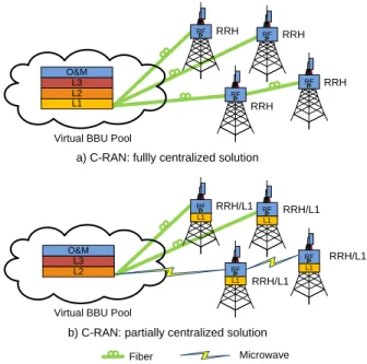
1) PHY layer architecture in C-RAN: There are two ap-proaches on how to split base station functions between RRH and BBU within C-RAN in order to reduce transport network overhead.
In the fully centralized solution, L1, L2 and L3 func-tionalities reside in the BBU Pool, as shown in Figure 9a. This solution intrinsically generates high bandwidth IQ data transmission between RRH and BBU.
In partially centralized solution, shown in Figure 9b, L1 pro-cessing is co-located with the RRH, thus reducing the burden in terms of bandwidth on the optical transport links, as the demodulated signal occupies 20 - 50 times less bandwidth [6] than the modulated one. This solution is however less optimal because resource sharing is considerably reduced and advanced features such as CoMP cannot be efficiently supported. CoMP benefits from processing the signal on L1, L2 and L3 in one BBU Pool instead of in several base stations [6]. Therefore a fully centralized solution is more optimal. Other solutions, in between the two discussed above, have also been proposed, where only some specific functions of L1 processing are co-located with the RRH, e.g., L1 pre-processing of cell/sector specific functions, and most of L1 is left in the BBU [57].
2) Physical medium: As presented in [10], only 35% of base stations will be connected through fiber, and 55% by wireless technologies, the remaining 10% by copper on a global scale in 2014. However, the global share of fiber connections is growing. In North America the highest percentage of backhaul connections will be done over fiber - 62.5% in 2014 [58].
Fiber links allow huge transport capacity, supporting up to tens of Gbps per channel. 40 Gbps per channel is now commercially available, while future systems will be using 100 Gbps modules and higher, when their price and maturity will become more attractive [6].
Typical microwave solutions offer from 10 Mbps-100 Mbps up to 1 Gbps range [59], the latter available only for a short
RF
RF
a) C-RAN: fullly centralized solution Virtual BBU Pool
L1 RRH RRH RRH RF RF RRH RF RF
b) C-RAN: partially centralized solution Virtual BBU Pool
RRH/L1 RRH/L1 RRH/L1 RF RF RRH/L1 Fiber Microwave L1 L1 L1 L1 L2 L3 O&M L2 L3 O&M
Fig. 9: C-RAN architecture can be either fully or partially centralized depending on L1 baseband processing module location.
range (up to 1.5 km) [58]. In [60] Ghebretensaeet al.propose to use E-band microwave transmission in (70/80 GHz) between BBU Pool and RRH. They proved that E-band microwave transmission can provide Gbps capacity, using equipment currently available commercially (2012) on the distance limited to 1-2 km to assure 99.999% link availability and 5-7 km when this requirement is relaxed to 99.9% availability. In the laboratory setup they have achieved 2.5 Gbps on microwave CPRI links. This supports delivering 60 Mbps to the end user LTE equipment.
For small cells deployment, Wi-Fi is seen as a possible solution for wireless backhauling [56]. Therefore, using the same solutions, Wi-Fi can potentially be used for fronthauling. The latest Wi-Fi standard, IEEE 802.11ad, can achieve the maximum theoretical throughput of 7 Gbps. However, the solution is not available on the market yet (2013).
The solution based on copper links is not taken into account for C-RAN, as Digital Subscriber Line (DSL) based access can offer only up to 10-100 Mbps.
To conclude, full C-RAN deployment is currently only possible with fiber links between RRH and BBU Pool. In case C-RAN is deployed in a partially centralized architecture, microwave can be considered as a transport medium between RRHs and BBU Pool.
B. Transport network
As fiber is the most prominent solution for the physical medium, its availability for the network operator needs to be taken into account choosing the optimal transport network solution. Moreover, operators may want to reuse their existing
deployments. Various transport network solutions are discussed below [6].
1) Dark fiber: Dark fiber is a preferred solution for a BBU Pool with less than 10 macro base stations [6], due to capacity requirements. Dark fiber can be deployed fast and with low cost, because no additional optical transport network equip-ment is needed. On the other hand, this solution consumes significant fiber resources, therefore network extensibility is a challenge. New protection mechanisms are required in case of failure, as well as additional mechanisms to implement O&M are needed. However, those challenges can be answered. It is fairly inexpensive to upgrade/add new fibers. CPRI products are offering 1+1 backup/ring topology protection features. If dark fiber is deployed with physical ring topology it offers resiliency similar to SDH. O&M capabilities can be introduced in CPRI.
2) WDM/OTN: Wavelength-division multiplexing (WDM)/Optical Transport Network (OTN) solutions are suitable for macro cellular base station systems with limited fiber resources, especially in the access ring. The solution improves the bandwidth on BBU-RRH link, as 40-80 optical wavelength can be transmitted in a single optical fiber, therefore with 10 Gbps large number of cascading RRH can be supported, reducing the demand on dark fiber. On the other hand, high cost of upgrade to WDM/OTN need to be covered. However, as the span on fronthaul network does not exceed tens of kilometers, equipment can be cheaper than in long distance backbone networks. Usage of plain WDM CPRI transceivers was discussed and their performance was evaluated in [61]. [11] applies WDM in their vision of C-RAN transport network.
In [62] Ponzini et al. describe the concept of non-hierarchical WDM-based access for C-RAN. The authors have proven that WDM technologies can more efficiently support clustered base station deployments offering improved flexibil-ity in term of network transparency and costs. Using that con-cept already deployed fibers, such as Passive Optical Networks (PONs) or metro rings, can be reused to carry any type of traffic, including CPRI, on a common fiber infrastructure. By establishing virtual P2P WDM links up to 48 bidirectional CPRI links per fiber can be supported.
For scarce fiber availability ZTE proposes enhanced fiber connection or xWDM/OTN [54]. Coarse WDM is suitable to be used for TD-SCDMA, while Dense WDM for LTE, due to capacity requirements.
OTN is a standard proposed to provide a way of su-pervising client’s signals, assure reliability compared with Synchronous Optical NETworking (SONET)/SDH network as well as achieve carrier grade of service. It efficiently supports SONET/SDH as well as Ethernet and CPRI. CPRI can be transported over OTN over low level Optical channel Data Unit (ODU)k containers as described in ITU-T G.709/Y.1331 [63], [64].
3) Unified Fixed and Mobile access: Unified Fixed and Mo-bile access, like UniPON, based on Coarse WDM, combines fixed broadband and mobile access network. UniPON provides both PON services and CPRI transmission. It is suitable for indoor coverage deployment, offers 14 different wavelengths
per optical cable, reducing overall cost as a result of sharing. However, it should be designed to be competitive in cost. Such a WDM-OFDMA UniPON architecture is proposed and examined in [65], and a second one, based on WDM-PON in [60]. In [60], referenced also in section V-A2, Ghebretensae et al. propose an end-to-end transport network solution based on Dense WDM(-PON) colorless optics, which supports load balancing, auto configuration and path redundancy, while min-imizing the network complexity. In [66] Fabrega et al. show how to reuse the deployed PON infrastructure for RAN with RRHs. Connections between RRHs and BBUs are separated using very dense WDM, coherent optical OFDM helps to cope with narrow channel spacings.
4) Carrier Ethernet: Carrier Ethernet transport can also be directly applied from RRH towards BBU Pool. In that case, CPRI2Ethernet gateway is needed between RRH and BBU Pool. CPRI2Ethernet gateway needs to be transparent in terms of delay. It should offer multiplexing capabilities to forward different CPRI streams to be carried by Ethernet to different destinations.
The term Carrier Ethernet refers to two things. The first is the set of services that enable to transport Ethernet frames over different transport technologies. The other one is a solution how to deliver these services, named Carrier Ethernet Trans-port (CET). Carrier Ethernet, e.g., Provider Backbone Bridge - Traffic Engineering (PBB-TE) is supposed to provide carrier - grade transport solution and leverage the economies of scale of traditional Ethernet [67]. It is defined in IEEE 802.1Qay-2009 standard. It evolved from IEEE 802.1Q Virtual LAN (VLAN) standard through IEEE 802.1ad Provider Bridges (PB) and IEEE 802.1ah Provider Backbone Bridges (PBB). To achieve Quality of Service (QoS) of Ethernet transport service, traffic engineering is enabled in Carrier Ethernet. PBB-TE uses the set of VLAN IDs to identify specific paths to given MAC address. Therefore a connection-oriented forwarding mode can be introduced. Forwarding information is provided by management plane and therefore predictable behavior on predefined paths can be assured. Carrier Ethernet ensures 99.999% service availability. Up to 16 million customers can be supported which removes scalability problem of PBB-TE predecessor [68].
The main challenge in using packet passed Ethernet in the fronthaul is to meet the strict requirements to synchroniza-tion and syntonizasynchroniza-tion. Synchronizasynchroniza-tion refers to phase and syntonization to the frequency alignment, respectively. Base stations need to be phase and frequency aligned in order to, e.g., switch between uplink and downlink in the right moment and to stay within their allocated spectrum. For LTE-A frequency accuracy needs to stay within ±50ppb (for a wide area base station) [6.5 in [69]] while phase accuracy of±1.5µs
is required for cell with radius ≤3km [70]. C. Network equipment
The following network equipment has been developed for usage in C-RAN architecture.
1) CPRI2Ethernet gateway: If Ethernet is chosen as a trans-port network standard, CPRI2Ethernet gateway is needed to
map CPRI data to Ethernet packets, close to or at the interface of RRH towards BBU Pool. Patents on such a solutions have been filed, see for example, [71].
2) IQ data routing switch: China Mobile Research Institute developed a large scale BBU Pool supporting more than 1000 carriers in 2011. The key enabler of this demonstration was a IQ data routing switch [6]. It is based on a Fat-Tree architecture of Dynamic Circuit Network (DCN) technology. In Fat-Tree topology multiple root nodes are connected to separate trees. That ensures high reliability and an easy solution to implement load balancing between BBUs. China Mobile has achieved real time processing and link load balancing. In addition, resource management platform has been implemented.
3) CPRI mux: CPRI mux is a device that aggregates traffic from various radios and encapsulates it for transport over a minimum number of optical interfaces. It can also implement IQ compression/decompression and have optical interfaces: for Coarse WDM and/or Dense WDM. BBU Pool will be demultiplexing the signals multiplexed by the CPRI mux [10]. 4) x2OTN gateway: If OTN is chosen as a transport network solution, then CPRI/OBSAI to OTN gateway is needed to map signals from two standards. Altera has a Soft Silicon OTN processor that can map any client into ODU container [72]. The work was started by TPACK. Performance of CPRI and OBSAI over OTN transport network has been proven in [73] for e.g., C-RAN application.
D. IQ Compression schemes and solutions
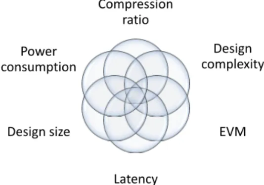
In C-RAN the expected data rate at the fronthaul link can be 12 to 55 times higher compared to data rate on the radio interface, depending on CPRI IQ sample width and modulation. RRHs transmit raw IQ samples towards BBU cloud, therefore, an efficient compression schemes are needed to optimize such a huge bandwidth transmission over capacity-constrained links. Potential solutions could be to reduce signal sampling rate, use non-linear quantization, frequency sub-carrier compression or IQ data compression [6]. Techniques can be mixed and a chosen scheme is a trade-off between achievable compression ratio, algorithm and design complex-ity, computational delay and the signal distortion it introduces as well as power consumption, as shown in Figure 10. The following techniques can be used to achieve IQ compression.
Reducing signal sampling rateis a low complex solution
having minimal impact on protocols, improves compression up to 66% with some performance degradation [6].
By applying non-linear quantization, more quantization levels are specified for the region in magnitude where more values are likely to be present. This solution improves Quanti-zation SNR (QSNR). Mature, logarithmic encoding algorithms, like µ-Law or A-law are available to specify the step size. Compression efficiency up to 53% can be achieved. This method creates additional Ir interface complexity (interface between RRH and BBU) [6].
IQ data compression can be done using e.g., Digital
Automatic Gain Control (DAGC) [6], [74]. This technique is based on reducing the signal’s dynamic range by normalizing the power of each symbol to the average power reference,
Compression ratio Design complexity EVM Latency Design size Power consumption
Fig. 10: Factors between which a trade off needs to be reached choosing an IQ compression scheme.
therefore reducing the signal dynamic range. This method affects Signal-to-noise ratio (SNR) and Error Vector Magnitude (EVM) deteriorates in DL. Potential high compression rate can be achieved, however the method has a high complexity and no mature algorithms are available.
One example of a frequency domain scheme is to
per-formsub carrier compression. Implementing the FFT/Inverse
FFT (IFFT) blocks in the RRH allows 40% reduction of Ir interface load. It can be easily performed in DL, however RACH processing is a big challenge. This frequency domain compression increases IQ mapping and system complexity. It also requires costly devices, more storage and larger FPGA processing capacity [6]. On top of that, it limits the benefits of sharing the equipment in C-RAN, as L1 processing needs to be assigned to one RRH. Several patents have been filed for this type of compression schemes.
In [75] Grieger et al. present design criteria for frequency domain compression algorithms for LTE-A systems which were then evaluated in large scale urban filed trials. Perfor-mance of JD under limited backhaul rates was observed. The authors proved that a Gaussian compression codebook achieves good performance for the compression of OFDM signals. The performance can be improved using Frequency Domain AGC (FDAGC) or decorrelation of antenna signals. However, field tests showed very limited gains for the observed setups.
Samardzija et al. from Bell Laboratories propose an algo-rithm [76] which reduces transmission data rates. It removes redundancies in the spectral domain, performs block scaling, and uses a non-uniform quantizer. It keeps EVM below 8% (3GPP requirement for 64 QAM, as stated in [69]) for 17% of relative transmission data rate (compression ratio defined as transmission rate achieved after compression to the original one). The algorithm presented by Guo et al. [77], which authors are also associated with Alcatel-Lucent Bell Labs removes redundancies in spectral domain, preforms block scaling, and uses non-uniform quantizer. EVM stays within 3GPP requirements in simulations for 30% compression ratio. TD-LTE demo test results showed no performance loss for 50% compression ratio.
Alcatel-Lucent Bell Labs’ compression algorithm reduces LTE traffic carried over CPRI interface from 18 Gbps to 8 Gbps [10], achieving a 44% compression ratio.
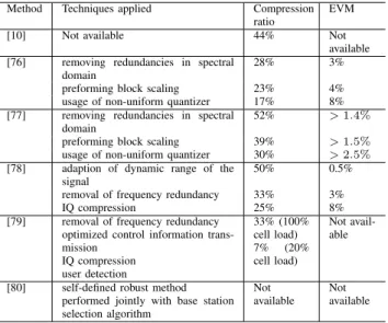
TABLE IV: Comparison of IQ compression methods. Com-pression ratio 33% corresponds to 3:1
Method Techniques applied Compression ratio
EVM
[10] Not available 44% Not
available [76] removing redundancies in spectral
domain
28% 3%
preforming block scaling 23% 4% usage of non-uniform quantizer 17% 8% [77] removing redundancies in spectral
domain
52% >1.4%
preforming block scaling 39% >1.5%
usage of non-uniform quantizer 30% >2.5%
[78] adaption of dynamic range of the signal
50% 0.5% removal of frequency redundancy 33% 3%
IQ compression 25% 8%
[79] removal of frequency redundancy optimized control information trans-mission IQ compression user detection 33% (100% cell load) 7% (20% cell load) Not avail-able
[80] self-defined robust method Not Not performed jointly with base station
selection algorithm
available available
The solution discussed in [78] adapts to the dynamic range of the signal, removes frequency redundancy and performs IQ compression creating 10.5 effective bits out of 12 bits of data. This method allows 50% to 25% of compression ratio introducing 0.5%1 to 8% of EVM and latency below1µsfor LTE signal.
Lorca et al. from Telefonica I + D in [79] propose a lossless compression technique where actual compression ra-tios depend upon the network load. For downlink direction, the algorithm removes redundancies in the frequency domain. Secondly, the amount of control data is reduced to minimum sending only the necessary information to reconstruct control signals at RRH. Moreover, a special constellation coding is used to reduce number of bits needed to represent constella-tion symbols for QPSK, 16QAM and 64QAM modulaconstella-tions. For uplink direction user detection is used to transmit only occupied carriers. Compression ratio of 33% is achieved at full cell load. Compression ratio up to 6.6% are achieved for 20% cell load.
Park et al. [80] propose a robust, distributed compression scheme applicable for UL transmission, which they combine with an efficient base station selection algorithm. Their current work focuses on implementing layered compression strategy as well as joint decompression and decoding. Results in terms of compression ratio and EVM are not available.
Table IV summarizes and compares various compression methods discussed in this Section. Compression of 33% is achieved by all the algorithms for which the ratio was avail-able. The best result, where the algorithm is known, is achieved by [76] and by [79] under small network load.
To conclude, in order not to lose the cost benefit of BBU Pooling for renting a transport network, mobile network op-erator needs to either own substantial amount of fiber or use
1equivalent to test equipment
an IQ compression scheme. Moreover, the cost of the optical high speed module must stay comparable to traditional SDH transport equipment in order to make C-RAN economically attractive.
VI. RRHDEVELOPMENT
In this section we present requirements and solutions for RRH that are compatible with C-RAN. The existing RRHs are expected to work in a fully centralized C-RAN architecture in a plug-and-play manner. In case of partially centralized C-RAN architecture L1 needs to be incorporated in RRH.
The biggest difference between RRHs deployed for C-RAN compared to previous solutions is that in C-RAN transmission the signal occurs over many kilometers, while in the latter architecture this distance is shorter, typically up to few kilo-meters. Therefore the additional delay caused by increased transmission distance needs to be monitored.
In addition, the higher bit rates need to be supported. In order to transport 10 Gbps CPRI rate, the maximum CPRI line bit rate option 8, i.e., 10.1376 Gbps needs to be deployed, which is supported so far by standard CPRI v 6.0 [20]. Additional upgrade of the standard is needed to accommodate more traffic, at least 16 Gbps to fully serve a 3 sector 20 MHz LTE macro cell with 4x2 MIMO [10], see Table II. Existing standards - CPRI and OBSAI can support connections between the BBU Pool and RRHs in C-RAN. Moreover, NGMN in [81] envisions ORI as a future candidate protocol. However, as the nature of the interface between RRH and BBU is changing with an introduction of C-RAN, the existing protocols may need to be redefined in order to be optimized for high volume transmission over long distances.
Alcatel-Lucent is offering a lightRadio solution for C-RAN [10]. It uses a multiband, multistandard active antenna array, with MIMO and passive antenna array support. Alcatel-Lucent is working towards two multiband radio heads (one for high and one for low bands). Built-in digital modules are used for baseband processing. For C-RAN L1, L2 and L3 are separated from radio functions.
In 2012, Ericsson announced the first CPRI over microwave connection implementation [82], which is interesting for op-erators considering the deployment of a partially centralized C-RAN architecture.
VII. SYNCHRONIZEDBBU IMPLEMENTATION
In this section we provide considerations on possible BBU implementation. We discuss the advantages and disadvantages of different processors types that can be used in C-RAN.
The interconnection between BBUs is required to work with low latency, high speed, high reliability and real time transmission of 10 Gbps. Furthermore, it needs to support CoMP, dynamic carrier scheduling, 1+1 failure protection and offer high scalability. Dynamic carrier scheduling implemented within the BBU Pool enhances redundancy of BBU and increases reliability.
The BBU Pool needs to support 100 base stations for a medium sized urban network (coverage 5x5 km), 1000 base stations for 15x15 km [6]. In addition, it is beneficial
when BBU has the intelligence to support additional services like Content Distribution Network (CDN), Distributed Service Network (DSN) and Deep Packet Inspection (DPI) [13].
Virtualization of base station resources is needed to hide the physical characteristics of the BBU Pool and enable dynamic resource allocation.
There are also challenges for real time virtualized base station in centralized BBU Pool, like high performance low-power signal processing, real time signal processing, BBU interconnection as well as between chips in a BBU, BBUs in a physical rack and between racks.
Optimal pooling of BBU resources in needed in C-RAN. In [31] Bhaumiket al.propose resource pooling scheme to mini-mize the number of required compute resources. The resource pooling time scale is of the order of several minutes, however, it can be expected it can be done with finer granularity further optimizing the results.
A. Current multi-standard open platform base station solu-tions
Operators need to support multiple standards, therefore multi-mode base stations are a natural choice. They can be deployed using either pluggable or software reconfigurable processing boards for different standards [6].
By separating the hardware and software, using e.g., SDR technology, different wireless standards and various services can be introduced smoothly. Currently base stations are built on proprietary platforms (vertical solution). C-RAN is intended to be build on open platforms in order to relief mobile opera-tors from managing multiple, often non-compatible platforms. C-RAN provides also higher flexibility in network upgrades and fosters the creation of innovative applications and services. B. Processors
Nowadays, Field-Programmable Gate Arrays (FPGAs) and embedded Digital Signal Processor (DSP) are used for wireless systems. However, the improvement in the processing power of General Purpose Processor (GPP) used in IT is giving the possibility to bring IT and telecom worlds together and use flexible GPP-based signal processors.
DSPs are developed to be specially optimized for real-time signal processing. They are powerful and use multicore (3-6) technology with improved processing capacity. What is important for C-RAN, a real time OS running on DSP facilitates virtualization of processing resources in a real time manner. However, there is no guarantee of backwards com-patibility between solutions from different, or even from the same manufacturer, as they are built on generally proprietary platforms.
Texas Instruments [14] favors the usage of specialized wireless System on a Chip (SoC), providing arguments that SoC consumes one-tenth of the power consumed by a typical server chip, and has wireless accelerators and signal processing specialization. Considerations about power consumption of signal processors are essential to achieve reduction in power consumption for C-RAN architecture compared to the tradi-tional RAN. In addition, for the same processing power, a
TABLE V: DSP and GPP processors
DSP GPP
Flexibility dedicated solution general purpose Vendor compatibility vendor specific,
propri-etary
higher compatibility be-tween vendors Backward compatibility limited assured Power consumption lower higher
Real-time processing optimized, achieved only possible with high power hardware Virtualization of BBU possible possible
DSP solution will also have a lower price compared to GPP. In [83] Wei et al.present an implementation of SDR system on an ARM Cortex-A9 processor that meets the real-time requirements of communication system. As SDR technology further enables to benefit from C-RAN this is an important proof of concept.
GPPs are getting more and more popular for wireless signal processing applications. The usage of GPP is facilitated by muli-core processing, single-instruction multiple data, low latency off-chip system memory and large on-chip caches. They also ensure backward compatibility, which makes it possible to smoothly upgrade the BBU. Multiple OS’s with real-time capability allow virtualization of base station signal processing.
China Mobile Research Institute proved that commercial IT servers are capable of performing signal processing in a timely manner. Intel is providing the processors for both C-RAN and traditional RAN [13]. More on Intel GPP solutions for DSP can be found in [84]. In [85], Kai et al. present a prototype of a TD-LTE eNB using a GPP. It did not meet real-time requirements of LTE system, which is of great concern when using general processors for telecommunication applications. It used 6.587 ms for UL processing, with turbo decoding and FFT taking most of it and 1.225 ms for DL processing, with IFFT and turbo coding being again the most time consuming. However, this system was based on a single core, and multi-core implementation with 4 multi-cores should make the latency fall within the required limits. Another approach to reach the requirements is to optimize the turbo decoder as described in [86], where Zhang et al.prove that using multiple threads and a smart implementation, 3GPP requirements can be met. De-Rate Matching and demodulation have been optimized for GPP used for LTE in [87]. In [88] Kaitzet al.propose to introduce a dedicated co-processor optimized for wireless and responsible for critical and computation intensive tasks. This optimizes power consumption at the cost of decreased flexibility. They have considered different CPU partitioning approaches for LTE-A case.
The issue of real-time timing control and synchronization for SDR has been addressed in [89]. A real-time and high precision clock source is designed on a GPP-based SDR platforms and users are synchronized utilizing Round-Trip Delay (RTD) algorithm. The mechanism is experimentally validated.