Development of a High Energy Hydrogen Beam Injection System
for Divertor Plasma Simulation Experiments on the DT-ALPHA
Device
∗
)
Peerapat BOONYARITTIPONG, Hiroyuki TAKAHASHI, Sumio KITAJIMA,
Atsushi OKAMOTO
1), Kenji TOBITA, Takahiko KOBAYASHI, Takeshi SAIKYO,
Yusuke ISHIKAWA, Kenta OGASAWARA and Hidetoshi HASHIZUME
Department of Quantum Science and Energy Engineering, Tohoku University, Sendai 980-8579, Japan1)Department of Applied Energy, Nagoya University, Nagoya 464-8603, Japan
(Received 28 December 2017/Accepted 25 June 2018)
Using the SIMION program, we have calculated the trajectories of hydrogen ions to investigate the effects of anE×Bfilter to be used for hydrogen ion beam injection experiments. The geometry we have utilized for the simulation matches the ion beam transport system of the DT-ALPHA device. Before investigating the hydrogen ion trajectories, we calculated helium ion trajectories and compared the results with experiments using a helium ion beam to confirm the results of the SIMION calculations. We then calculated the trajectories of the hydrogen ions H+, H+2, and H+3. We found that the electric field required to select an H+ion beam differs from that obtained from a theoretical calculation, and we interpret this as a result of the fringe fields of theE×Bfilter. We have also evaluated the H+ion beam size at the ion entrance aperture using SIMION. This calculation indicates that spreading of the hydrogen ions along the electric and magnetic fields differs because of non-homogeneous fields and the fringe fields of the filter. In addition, we have investigated the trajectories and beam sizes of He+ion beams, we found that theE×Bfilter has no significant influence on the He+ion beam experiments.
c
2018 The Japan Society of Plasma Science and Nuclear Fusion Research
Keywords: hydrogen, ion beam transport, ion-trajectory simulation, divertor, volumetric recombination DOI: 10.1585/pfr.13.3402102
1. Introduction
A crucial problem for magnetically confined fusion studies is to control the enormous heat load flowing into the divertor plates, and a detached divertor formation is a promising candidate for reducing the plasma heat load. Plasma volumetric recombination plays an important role in detached divertor formation. This has been investi-gated for heat load control for diverted toroidal devices and for divertor plasma simulators [1, 2]. In lower elec-tron temperature regions, typicallyTe<1 eV, electron-ion
recombination (EIR)—and particularly three-body recom-bination and radiative recomrecom-bination—dominates plasma detachment. Conversely, in a molecular system, plasma detachment proceedsviamolecular assisted recombination (MAR) [3]. In a region whereTe>1 eV, the MAR process
has a larger reaction rate than the EIR process, but both EIR and MAR contribute to plasma detachment. How-ever, electrons that flow into the divertor region from the scrape-off layer have much higher electron temperatures than those required for volumetric recombination. The gas puffing method is therefore widely utilized to remove elec-tron energy [4,5], since maintaining a low elecelec-tron
temper-author’s e-mail: [email protected]
∗)This article is based on the presentation at the 26th International Toki Conference (ITC26).
ature plasma in the divertor region is important for steady-state heat load mitigation. However, energetic plasma particles are periodically exhausted by the edge-localized modes (ELMs) that are associated with improved plasma confinement [6]. The energies of the exhausted plasma particles can potentially rise to several keV. This raises the concern that the volumetric recombination reaction rate in the divertor region may be decreased by the presence of the energetic particles. For example, it has been found that the reaction rate for the EIR process is reduced by ener-getic electrons [7]. However, the influence of enerener-getic ion collisions on volumetric recombination has not been well investigated, because conventional divertor plasma simu-lators have difficulty in utilizing energetic ions. An alter-native plasma source is therefore required to conduct an experimental study of this subject.
We have proposed an ion beam injection experiment using a radio-frequency plasma source and an ion beam generator. We have investigated the influence of energetic-ion collisenergetic-ions using helium energetic-ion beams and a helium EIR plasma, because helium ions exist in the divertor region [8], and it is indicated that energetic ion collisions decrease the reaction rate of the helium EIR process [9].
However, the fuels of a fusion reactor are hydrogen isotopes rather than helium ions. Therefore, experiments
c
2018 The Japan Society of Plasma
with hydrogen ion beams and hydrogen target plasmas are necessary to understand divertor plasma dynamics. A hy-drogen plasma includes ion species such as H+, H+2, and H+3.
Generally, an ion beam is produced using an accel-erating electrode, and the energies of the ions are deter-mined by the acceleration potential. However, the velocity of each ion depends upon its mass, and the cross-section for an ion collision depends upon its velocity. Therefore, it is suitable to utilize mono-velocity hydrogen beams to in-terpret the experimental results. To obtain a mono-velocity ion beam, it is necessary to separate the ion species. One promising approach is to employ an E×B filter, which uses electric and magnetic fields, because it requires less space than other methods. An E×Bfilter can therefore minimize the ion beam travel distance for our device. On the other hand, we anticipate that some problems may arise from introducing an E×Bfilter into our device: (1) the effect of fringe fields and non-homogeneous fields, (2) the effect on the waist size of the H+ ion beam, and (3) the effect on the waist size of a He+ion beam. In the present paper, we report the results of a simulation study of the introduction of anE×Bfilter into our device, aiming ul-timately for the production of hydrogen ion beams.
2. Method of Simulation
We have been conducting divertor simulation ex-periments using the radio-frequency plasma source DT-ALPHA and an ion beam generator. As described in Sec. 1, the current system is not equipped with anE×B
filter. In the present work, we have therefore calculated ion beam trajectories using the simulation program SIMION 7.0 [10] in order to investigate the effects of theE×B fil-ter. SIMION (developed at the Idaho National Engineering Laboratories) is a program that simulates the motions of charged particles in electrostatic and magnetic fields. The geometry we utilized for the simulation was designed to match the ion beam transport system of the DT-ALPHA device, as described below in this section. We also describe here the details of the ion beam production and transport system. Note that we have not included space-charge ef-fects in the present simulations.
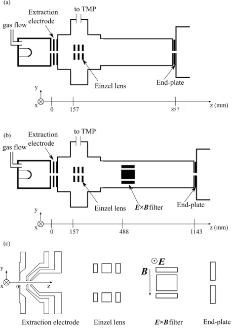
In the current beam transport system, an ion beam is extracted by using an extraction electrode and is injected into the DT-ALPHA device through an plate. The end-plate has an aperture with a 10 mm inner diameter. To optimize ion beam transport, we have installed an einzel lens to focus the ion beam at the end-plate. Figure 1 (a) illustrates the beam extraction and transport system in the DT-ALPHA device before the installation of theE×B fil-ter. We plan to install theE×Bfilter between the einzel lens and the end-plate, as shown in Fig. 1 (b). The com-ponents we have used in the simulations are illustrated in Fig. 1 (c). In the simulations, the x, y, andz-axes are aligned with the magnetic field, electric field, and ion beam
Fig. 1 Schematic drawing of the beam transport system for the DT-ALPHA device (a) without theE×Bfilter and (b) with theE×Bfilter. (c) The model of the components utilized in the simulation.
direction, respectively. The model consists of an extraction electrode, an einzel lens, anE×Bfilter, and an end-plate. The extraction electrode has three components: an accel-eration electrode, a decelaccel-eration electrode, and a grounded electrode upstream from the beam. Each electrode has an aperture with a 6 mm inner diameter. The distance between the acceleration and deceleration electrodes was 11 mm, and that between the deceleration electrode and the grounded electrode was 3 mm. The einzel lens consists of three square electrodes, with sizes of 60×60 mm2, and each electrode contains a 30 mm diameter aperture. The thickness of the middle electrode is 14 mm, and each of the two outer electrodes is 7 mm thick. The distance between each electrode is 5 mm. The E×Bfilter, which we plan to install 488 mm from the acceleration electrode, consists of a pair of electrodes and a pair of permanent magnets. Each electrode has dimensions 80×40×8 mm3, with the
distance between the electrodes being 35 mm. Each mag-net has dimensions 80×50×5 mm3, with the distance
3. Ion Trajectory Simulations Using
SIMION
We performed the simulations reported in Sec. 3.1 uti-lizing an extraction-electrode model that consists of accel-erating, decelaccel-erating, and grounded electrodes. The initial energy of the ions was set to zero, and the electrostatic field formed around the three electrodes determines the energies of the ions. On the other hand, the simulations described in Sec. 3.2 to Sec. 3.4 did not utilize the extraction elec-trode. In those cases, the energies and divergences of the ion beams were initially defined, instead of being deter-mined by the extraction electrode.
3.1
Comparison of SIMION results with
experiments
Before investigating the effect of the E×Bfilter, we conducted beam-extraction experiments without theE×B
filter, in order to compare the results with the simulation results of the SIMION program. In the beam transport sys-tem, we utilize an einzel lens to optimize ion beam trans-port. In this experiment, we determined the einzel lens po-tentialVein—at which the helium ion beam current, as
mea-sured by a Faraday cup with an 8 mm diameter aperture in front of the end-plate, has its maximum value—for various accelerating voltagesVacc. In the simulation, we positioned
the He+ions from−3 mm to+3 mm inx-axis near the ex-traction aperture to cover the aperture size (6 mm). We determined the optimal einzel lens potential from the sim-ulation as follows: First, we calculated the trajectories of the ions for various einzel lens potentials. Then we inves-tigated the number of ions arriving at the spatial position of the Faraday cup (φ=8 mm) to find einzel lens potential which maximizes the number of ions reaching the Faraday cup. Figure 2 shows the ratio ofVeintoVacc as a function
of the accelerating voltage. The filled and open circles cor-respond to the experiment and the simulation, respectively. As shown in Fig. 2, the ratioVein/Vacc, as determined by
both the experiment and the simulation, was almost same value, 0.6, over a wide range of accelerating voltages. Over the rangeVacc =6 - 12 kV, the simulation results yielded a
slightly higher ratio than did the experiments. Although an understanding of this difference remains for future work, this result confirms that the SIMION program can be uti-lized for predicting ion beam trajectories under the influ-ence of theE×Bfilter.
3.2
Simulation of ion separation
We next investigated hydrogen ion separation with the
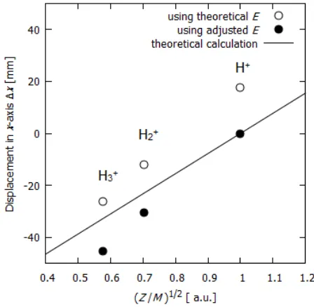
E×Bfilter. We fixed the energies of the ions in the sim-ulation at 10 keV, since the energies of particles exhausted by ELMs potentially rise to several keV. The simulation results are summarized in Fig. 3. The horizontal axis rep-resents the ratio of the ionic charge numberZto the ionic massM. In this simulation, each ion has an initial velocity vector parallel to thez-direction and is initially positioned
Fig. 2 The optimal einzel potential, which yields the most in-tense helium ion beams, for various accelerating voltages.
Fig. 3 DisplacementsΔxof each type of 10 keV hydrogen ion.
atx=0 mm. Each ion moves along thez-axis before en-tering the E×Bfilter. The x-axis velocity then changes because of the magnetic and electric fields of the E×B
filter.
We measured thex-axis positions of the ions 100 mm behind the E×Bfilter; the vertical axis in Fig. 3 repre-sents the displacement from z-axis at this location. The electric field required to produce a given x-axis displace-ment of the hydrogen ions can easily be calculated from the balance betweenZeEandZevB, wherevis thez-axis velocity of the hydrogen ions. This relation yields an elec-tric field E = 1.4×10⁵V/m in the homogeneous
the solid line represents the theoretically calculated dis-placement of the ions using the homogeneous electric field
E =1.4×10⁵V/m (generated by applying±2.4 kV to the electrodes). The open circles represent the displacement
Δxobtained from a simulation using the same fieldE. As shown in Fig. 3, the displacement of the H+ions obtained by usingE=1.4×10⁵V/m in the simulation clearly
dif-fers from zero. In the theoretical calculation that uses ho-mogeneous fields inside theE×B filter, we ignored the fringe fields for simplicity. Consequently, this difference in displacement may be due to the fringes of the electric and magnetic fields in theE×Bfilter.
We next investigated the electric field required to com-pensate for the effects of the fringe fields. The filled cir-cles in Fig. 3 show the simulation results with the com-pensated electric fieldE = 1.6×10⁵V/m (generated by
applying±2.9 kV to the electrodes). The higher required electric field means that the fringe magnetic field has more effect on the beam trajectory than the fringe electric field. As shown in Fig. 3, the displacements of H+2 and H+3 ob-tained with the simulation also are larger than that obob-tained from the theoretical calculation. We consider this diff er-ence also to be due to the fringe fields. The simulation results thus indicate that the influence of the fringe fields is non-negligible for hydrogen ion beam separation.
We have also investigated the effects of stray magnetic fields from the DT-ALPHA device on beam injection by performing a simulation using H+ions with 10 keV ener-gies and with the electric field of theE×Bfilter set equal to 1.6×10⁵V/m. In addition, 10 mm behind the end-plate
we added two magnetic coils of strength 2×10⁻²T to
rep-resent the nearest electromagnetic coil pair in DT-ALPHA. This simulation result indicated that stray magnetic fields from DT-ALPHA have no significant effect on the ion tra-jectories before they enter the end-plate.
3.3
Simulation of H
+beam focusing
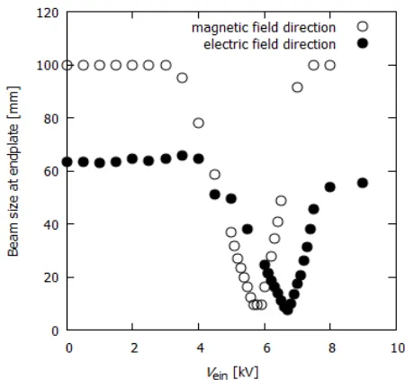
An ion beam is injected into the DT-ALPHA device through the 10 mm diameter aperture of the end-plate, so a beam size of 10 mm diameter or smaller is preferred. Ac-cordingly, we have evaluated the sizes of the H+beams for various einzel lens potentials, with the energies of the ions maintained at 10 keV. The divergence of this ion source has previously been investigated using a He+ion beam [11]. Although the He+ion species is different from the focus of the present study, we can evaluate the H+beam divergence using the approach described in Ref. 11.
We specified the angles of the initial ion trajectories relative to thez-axis to range from−1 degree to+1 degree, and the ions spread along the electric and magnetic fields simultaneously. However, for simplicity, we have investi-gated the spreading of the ions in each direction separately. The results are summarized in Fig. 4. The horizontal axis represents the potential of the einzel lens, and the vertical axis represents the H+beam size at the end-plate, as
de-Fig. 4 Beam size at the end-plate of a 10 keV H+ ion beam evaluated from spreading along the magnetic and electric fields.
termined from the lowest and highest landing positions of the ions at the end-plate on the respective axes. The open and filled circles correspond to H+ions spreading along the magnetic and electric fields, respectively. Here the electric field of theE×Bfilter that we utilized in the simulation wasE = 1.6×10⁵V/m. As shown in Fig. 4, the
spread-ing of the ions differs for the electric and magnetic field directions. As described in Sec. 3.2, fringe fields affect the beam trajectory, and in addition the fields inside theE×B
filter are spatially non-homogeneous. Therefore, possi-ble causes for the differences in ion spreading may be the fringe fields and the non-homogeneous fields. Although ion spreading can be compensated by the einzel lens, the optimal einzel lens potential for each direction is diff er-ent. This indicates that simultaneous compensation of ion spreading for both directions may be difficult. However, the optimal focusing potentials for the two directions are close to each other, which indicates that the maximum ion beam current can be expected aroundVein ∼ 6 kV. Since
the definition we have used for beam size does not reflect the actual distribution of the ion beam, and because the di-vergence used in the simulation may possibly have been overestimated, it will be important to confirm the optimal focusing potential by experiment, which is left as a task for the future.
3.4
E
ff
ect on He
+extraction
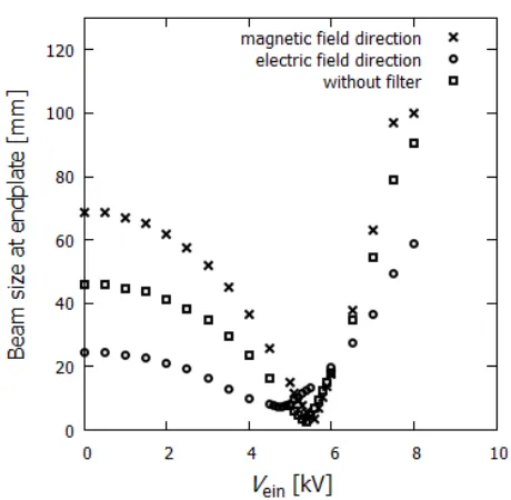
Fig. 5 Beam size of 10 keV He+ ion beams at the end-plate, as evaluated from spreading along the magnetic field, spreading along the electric field, and without theE×B filter.
beam size at the end-plate. The required electric field for He+—investigated in the same manner as in section 3.2— isE = 8.5×10⁴V/m (generated by applying±1.5 kV to
the electrodes). We also investigated the beam size of He+ at the end-plate using the same simulation model and sim-ilar conditions as in section 3.3. Figure 5 shows the re-sults. The definitions of the horizontal and vertical axes are same as in Fig. 4. The crosses and open circles repre-sent the beam size at the end-plate as evaluated from ion beam spreading along the magnetic and electric fields, re-spectively. The open squares represent the beam size at the end-plate for the case without theE×Bfilter. Similar to the H+ion simulation, the einzel lens potential required to compensate for ion spreading is different for each direc-tion. However, the minimum beam size for the He+ions in each direction is almost the same as the beam size for the case without theE×Bfilter. Again, the spreading of the ions may be caused by fringe and non-homogeneous fields. The influence of these fields is smaller for He+, because the mass of He+is greater than that of H+. Consequently, the He+beam size at the end-plate is smaller than that of H+. We thus expect that the influence of theE×Bfilter on He+
beam experiments can be compensated.
4. Summary
We have investigated the effects of an E×B filter planned for installation in the DT-ALPHA device on hy-drogen ion beam transport. Our simulation results confirm that theE×Bfilter can effectively separate the hydrogen ions. Although the E×B filter causes an undesired di-vergence of the ion beam—which results in a larger beam waist size—this effect can be compensated by adjusting the potential applied to the einzel lens. We have also investi-gated the influence of theE×Bfilter on helium ions and have found that optimization of the einzel lens potential can compensate for the influence on the helium ion trajec-tories. However, further optimization of the electric field in theE×Bfilter and of the einzel lens potential remain to be investigated experimentally. Installation of theE×B
filter is now in progress.
Acknowledgement
The work was partly supported by the Japan Society for the Promotion of Science (JSPS) Grants-in-Aid for Sci-entific Research (KAKENHI), 26420848 and Grant-in-Aid for Young Scientists (B) 17K14895.
[1] D. Lumma, J.L. Terry and B. Lipschultz, Phys. Plasmas4, 2555 (1997).
[2] Y. Uesugi, N. Hattori, D. Nishijima, N. Ohno and S. Taka-mura, J. Nucl. Mater.290-293, 1134 (2001).
[3] P.K. Browning, U. Fantz, K.J. Gibson, B. Mihaljcic and D. Wunderlich, J. Nucl. Mater.337-339, 232 (2005).
[4] S. Takamuraet al., Plasma Sources Sci. Technol.11, A42 (2002).
[5] B. Schweer, G. Mank and A. Pospieszczyk, J. Nucl. Mater. 196-198, 174 (1992).
[6] H. Zohm, Plasma Phys. Control. Fusion38, 1213 (1996). [7] N. Ohno, D. Nishijima, S. Takamura, Y. Uesugi, M.
Motoyama, N. Hattori, H. Arakawa, N. Ezumi, S. Krasheninnikov, A. Pigarov and U. Wenzel, Nucl. Fusion 41, 1055 (2001).
[8] M. Shimadaet al., Phys. Rev. Lett.47, 796 (1981). [9] H. Takahashi, A. Okamoto, D. Nakamura, T. Miura,
P. Boonyarittipong and S. Kitajima, Phys. Plasmas 23, 112510 (2016).
[10] SIMION 3D, Version 7.0, INEEl-95/0403, Idaho National Engineering and Environmental Laboratory.