ADAPTIVE CODE TO USER
ALLOCATION FOR INTERFERENCE
MANAGEMENT ON THE DOWNLINK
DS-CDMA SYSTEMS
D.R. SRINIVAS*
E.C.E Department, G. Pulla Reddy Engineering College Kurnool-518007, Andhra Pradesh, India
K.E. SREENIVASA MURTHY
Principal, S.V.I.T. Anantapur, Andhra Pradesh, India
Abstract:
In CDMA systems interference is the major problem. Reducing the interference results in direct increase in system capacity. This interference reduction can be controlled by investing additional por per user at the transmitter or by using spreading codes. The use of any orthogonal code spreading sequences provides excellent performance for the downlink of DS-CDMA systems in Additive White Gaussian noise (AWGN) channels. However, the hostile nature of the wireless channel can severely degrade the orthogonality of such sequences and unless compensated for at the receiver it will result in significant Multiple access interference (MAI). The MAI experienced by the different users depends on the cross correlations of the user’s codes as ll as the instantaneous values of the user’s data symbols to be transmitted. The principle of the proposed technique is to exploit the dependency of multiple access interference on the instantaneous symbol values of active users. This paper implements the CDMA transmitter and receiver algorithm for both Adaptive code allocation, fixed code allocation with different loads.
Keywords: Walsh-Hadamard; Multiple access interference (MAI); DS-CDMA; Bit error rate (BER); Signal to noise ratio (SNR).
1. Introduction
The use of orthogonal Walsh-Hadamard spreading sequences provides excellent performance for the downlink of direct sequence code division multiple access (DS-CDMA) systems in additive white Gaussian noise (AWGN) channels. However, the hostile nature of the wireless channel can severely degrade the orthogonality of such sequences and unless compensated for at the receiver it will result in significant Multiple access interference (MAI). Optimizing the signature waveforms for transmission in DS-CDMA can greatly benefit a wireless communication system. Many researchers have proposed optimization of the spreading codes towards orthogonalizing the users in multipath scenarios which involved waveform design of the codes used taking into account the characteristics of the channel encountered.
2. Design Approach
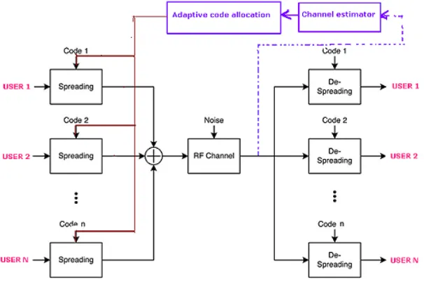
For the implementation of Communication system a CDMA based Spread spectrum communication architecture is developed. The communication model(conventional architecture) consisting of a Multiple user spread code transmitting unit takes Multiple user inputs and spreads using coding sequence allocated in a sequential manner as shown in figure.1. The receiver is designed as a rake receiver. In CDMA spread spectrum systems, the chip rate is typically much greater than the flat fading bandwidth of the channel. Conventional modulation and receiver techniques require an equalizer to undo the ISI between adjacent symbols. CDMA spreading codes are designed to provide very low correlation between successive chips. Propagation delay spread in the radio
*
channel provides multipath signal at the receiver. If multipath components are delayed in time by more than one chip duration (1/Rc), they appear like uncorrelated noise at a CDMA receiver, and equalization is not required.
If, in a mobile radio channel reflected waves arrive with small relative time delays, self interference occurs. Direct Sequence (DS) Spread Spectrum is often claimed to have particular properties that makes it less vulnerable to multipath reception. In particular, the rake receiver architecture avoids wave cancellation (fades) if delayed paths arrive with phase differences and appropriately weighs signals coming in with different signal-to-noise ratios. Rake receivers are used in CDMA systems for two reasons, the 1st reason is inter-symbol interference cancellation and the second reason is to utilize the multi-path diversity .The idea of a Rake receiver is to identify a number of different multi-path components and align them constructively, both in time and phase, thus utilizing the created multi-path diversity.
The MAI effect is to be reduced to improve the estimation. In such MAI PN codes are used. These codes are not able to overcome the effects under dynamic channel condition. Hence there is a need to adaptive code allocation with adaptive channel effect. For the implementation of Adaptive code the conventional architecture is modified as shown in Fig. 2.
Fig. 1. Spread spectrum architecture (conventional architecture) Fig. 1. Spread spectrum architecture (conventional architecture)
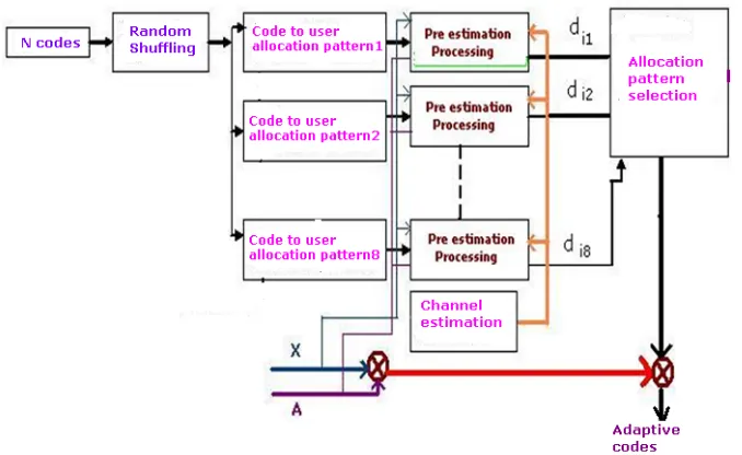
In the suggested approach an adaptive code allocation unit with channel estimator is incorporated with the conventional architecture. An adaptive code selection is carried out with pre estimation processing in the transmission side for best code selection is as shown in fig.3.
3. Operational Algorithm
In the downlink transmission of a synchronous CDMA system of K users under frequency selective fading, where the channels’ path delays are assumed to be an integer number of the chip period. All codes and channels are assumed to have normalized energy of one and length of L and P chips, respectively. The data frame is N symbols long. Tband Tc are the symbol and chip periods, respectively. The received signal at the uthMU can be
expressed as
P p u pu c b k k k K k N ik
t
a
x
i
c
t
iT
pT
h
i
n
t
U
1 1 1
)
(
(1)where xk(i), ak, ckare the kthuser’s PSK modulated data symbol for the ithsymbol period, amplitude and code,
hpu(i) and nu(t) are the uthMU’s channel pthtap coefficient and AWGN noise corrupting the signal of interest.
The output of the Rake receiver of the uthuser can be expressed as
c pT b T i c pT b iT c b u pu u P piu
r
t
h
i
c
t
iT
pT
dt
d
) 1 ( 1)
(
)
(
)
(
(2)=
a
ux
iu+ MAI + noiseHere xiuis a compact representation of the desired (uth) user’s signal for the ithperiod of interest, MAIiuis the
cumulative MAI caused by the interfering K −1 users and ηiuis the noise component at the Rake output. If a
discrete time representation is adopted by sampling the signals at the chip rate with rectangular pulses then Tb,
Tccan be omitted and the above terms can be defined as
1 1 1]
[
]
[
P L l uu ku i N i n K u k k ik kiu
a
x
s
l
s
l
nl
MAI
kun i N i n K u k k ik kx
a
1 (3)
s
[l]
c
[l
p
]
h
u[p]
P p k ku
11
(4)Where hu[p] is the discrete time representation of hpu(i) and
1 1]
[
]
[
P L l uu kukun
s
l
s
l
nL
(5)is the cross-correlation of the users’ multipath-corrupted signature waveforms (sku). Evidently, even if
orthogonal codes are used the resulting cross correlation of the codes viewed at the receiver is non-zero due to the channel distortion. Furthermore, it should be clarified that, as in the majority of conventional pre coding schemes, the knowledge of the channel response for all receivers is required at the base station (BS) for the proposed pre coding. This can be made available by channel estimation at the transmitter in the time division duplex (TDD) transmission mode, which is assumed in this Thesis. It can be seen channel state information (CSI) and data knowledge readily available at the BS the decision variables at the receiver can be pre-estimated. By selecting the appropriate code allocation for transmission at each symbol period the factors can be influenced and hence the distribution of the diu values for all users can be improved to offer enhanced reliability in the
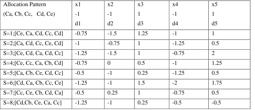
detection. For example of K = 5 users as shown in Table 1. Here the distributions of the decision variables for eight different code allocation patterns are depicted, for two different transmitted symbols combinations. The available spreading sequences and the allocation patterns are also shown for reasons of completeness. It can be seen that by changing the code-to-user allocation and hence the users’ cross-correlations, the decision variables are dramatically affected. It can also be viewed that some code allocations, e.g. s = 6, s = 1 for the first symbol combination, deliver better decision variables’ distributions than others, e.g. s = 4, s = 7. As mentioned above this is a derivative of the difference in the resulting interference for different code allocations. Consequently the detection can be made more reliable by optimizing the code-to-user allocation to be employed at each symbol period. This is why in the proposed method the code allocation to be used is dynamically adjusted to the symbols xik to be transmitted at the period i of interest. This is a way of “fine tuning” the users’ symbols and codes so that the energy in the channel be used constructively instead of being wasted because of data misalignment as in conventional methods. As a result the effective received SINR can be increased and improved decision variables can be delivered at the MUs’ receivers without the need to increase the transmitted per-user-power.
Table 1. Noiseless Decision variables distributions for different allocation patterns of a system for k=5 users with random codes of L= 16 for 8 allocation patterns.
Allocation Pattern (Ca, Cb, Cc, Cd, Ce)
x1 -1 d1 x2 -1 d2 x3 1 d3 x4 -1 d4 x5 1 d5 S=1;[Ce, Ca, Cd, Cc, Cd] -0.75 -1.5 1.25 -1 1 S=2;[Ca, Cd, Cc, Ce, Cd] -1 -0.75 1 -1.25 0.5 S=3;[Ce, Cd, Ca, Cd, Cc] -1.25 -1.5 1 -0.75 2 S=4;[Ce, Cc, Ca, Cb, Cd] -0.75 0 0.5 -1 1.25 S=5;[Ca, Cb, Ce, Cd, Cc] -0.5 -1 0.25 -1.25 0.5 S=6;[Cd, Ca, Cb, Cc, Ce] -1.25 -1 1.5 -2 1.75 S=7;[Cc, Ce, Cb, Cd, Ca] -0.5 0.25 1 -0.75 0.5 S=8;[Cd,Cb, Ce, Ca, Cc] -1.25 -1 0.25 -0.5 -0.5
4. Codes to User Allocation (CUA)
criterion which is explained in the following section. For reasons of simplicity, the analysis presented assumes Rake detection but the process for the case of Multi-user Detection (MUD) is easily deduced by analogy. In order to choose the appropriate code allocation pattern prior to transmission the expected decision variables at the MUs for all the available code-to-user allocation combinations need to be determined at the transmitter using the instantaneous symbol values for the active users.[1] Towards this end, in this thesis, the estimated effective cross correlation matrix Rs of dimensions K × K is formed for each allocation pattern at the BS from the estimated ρku in which the estimated channel coefficients hpu(i) are used .
KK K K K K sR
ˆ
ˆ
ˆ
ˆ
ˆ
ˆ
ˆ
ˆ
ˆ
ˆ
2 1 2 22 21 1 12 11 (6)The decision variables at the MUs outputs for the ith symbol period for the s th code-to-user allocation pattern can then be pre-estimated as
dis=[di1,s di2,s …. dik,s] =Xi AR s =d is +e is (7)
where Xi = [xi1xi2...xiK] is the 1 × K data matrix for the i th symbol period, A = diag([a1a2...aK]) is the K × K diagonal matrix of amplitudes and e isis the decision variable pre-estimation error due to inaccurate channel estimation. It should be clarified that at each symbol period a new matrix di is formed with the sthrow denoting
the pre-estimated decision variables of the users for the sthallocation pattern and the uth column denoting the
variables of the uth user for the various allocation patterns. The proposed algorithm works as shown in the
diagram in Fig.4. 1. Assuming Nc = K, at each symbol period and using the instantaneous values of Xi, the decision variables’ distribution for each of the pc allocation patterns is evaluated and the optimal pattern is chosen according to a selection criteria that will be presented below. Since the receiver has knowledge of all the pc available patterns it only needs to be informed about the index of which specific pattern is used at each symbol-period by a control signal of log2 (pc) bits transmitted at a different frequency/time slot as SI. By recognizing the correct pattern each MU can find the new code assigned to it for the current symbol detection as well as the remaining codes of the rest of the users to utilize for multi user detection (MUD). An alternative route towards performance improvement, also considered here for the sake of comparison, is using a larger number of codes (Nc > K) to attain a greater variety of interference distribution, but this would lead to the requirement for increased system resources, i.e. more available signature waveforms. It is noteworthy to highlight that the SI bits are transmitted simultaneously and do not need to be spread as the information they convey is common to all users and furthermore this would be more bandwidth efficient. If the number of SI bits is not a power of two or if the SI is to be forward error correction encoded, then a frame based approach can be adopted .Here the allocation procedure is run for all the symbols in the frame prior to transmission and the control bits for all symbols are transmitted in the beginning of the frame. Each symbol in the frame is a CDMA-Multiplexed symbol for K users.
5. Simulation Results and Discussion
allocation patterns formed for the cases of HLL, HHL, HAL, HLH, HLA, HHH, HAA, HLA, HHL, in an AWGN channel is depicted .The No. of users is k=3 and the spreading gain L=8. It is evident in figs that the receiver structure benefit from a significant performance improvement when combined with proposed technique. It should be noted that using High Load, with any fading and SNR is the No. of bit errors are increased compared to Low load. In figs 6. 3 the performance of the proposed method with 8 allocation patterns formed for the cases of ALL, AHL, AAL, ALH, ALA, AHH, AAA, ALA, AHL, in an AWGN channel is depicted .The no. of users is k=3 and the spreading gain L=8.It is evident in figs that the receiver structure benefit from a significant performance improvement when combined with proposed technique. It should be noted that using Avg Load, with any fading and SNR is the No. of bit errors are Average compared to Low load. Performance of rake receiver is depicted to show the proposed method‘s superiority i.e. for Adaptive code allocation BER is falling compared to fixed code allocation. As the load increases the system performance is decreasing.
5.1 Performance results:
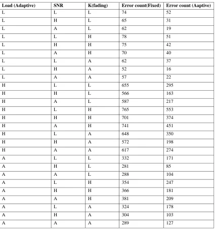
For the proposed adaptive code allocation and fixed code allocation comparison is done with respect to the number of errors. In case of fixed code allocation the number of errors is always higher than adaptive code allocation
Table 2.No.of Bit errors for Adaptive code allocation and fixed code allocation
Load (Adaptive) SNR K(fading) Error count(Fixed) Error count (Aaptive)
L L L 74 52
L H L 65 31
L A L 62 19
L L H 78 51
L H H 75 42
L A H 70 40
L L A 62 37
L H A 52 16
L A A 57 22
H L L 655 295
H H L 566 163
H A L 587 217
H L H 765 553
H H H 701 374
H A H 741 451
H L A 648 350
H H A 572 198
H A A 617 274
A L L 332 171
A H L 281 85
A A L 288 104
A L H 354 247
A H H 366 181
A A H 381 209
A L A 324 178
A H A 304 103
Low_SNR = 8, Average_ SNR = 15, High_ SNR = 22 Low_load = 50, Average_Load = 250, High_Load = 500
High_Fading = 1/2500, Average_ Fading = 1/8000, Low_ Fading = 1/10000
Error count is observed to be improved in Avg load, high SNR and avg fading case, HHA and HHH cases Case 1: SNR=8, Load=50, Fading=1/10000:
0 1 2 3 4 5 6 7 8
1 0- 0 . 4
1 0- 0 . 3
S N R (d B )
BE
R
B E R v/ s S N R fo r d e ve lo p e d s y s t e m
A d a p t ive S t a t ic
Overall system BER vs.SNR for Low load, Low SNR, Low fading Case 2: SNR=8, Load=50, Fading=1/2500
0 1 2 3 4 5 6 7 8
10-0.4 10-0.3
S NR (dB )
BER
B E R v/s S NR for developed s y s tem
A daptive S tatic
Overall system BER vs.SNR for Low load, Low SNR, High fading Case 3: SNR=22, Load=50, Fading=1/2500
0 5 10 15 20 25
10-0. 5
10-0. 4
10-0. 3
S NR (dB )
BER
B E R v/s S NR for developed s y s tem
A daptive S tatic
Case 4: SNR=8, Load=50, Fading=1/8000
0 1 2 3 4 5 6 7 8 10-0. 6
10-0. 5 10-0. 4 10-0. 3
S NR (dB )
BER
B E R v/s S NR for developed s y s tem
A daptive S tatic
Overall system BER vs.SNR for Low load, Low SNR, average fading Case 5: SNR=15, Load=500, Fading=1/2500
0 2 4 6 8 10 12 14
10-0 . 5
10-0 . 4
10-0 . 3
S N R (dB )
BER
B E R v/s S N R fo r develop ed s y s tem
A daptive S tatic
Overall system BER vs.SNR for high load, Avg SNR, high fading Case 6: SNR=8 , Load=500 , Fading=1/8000
0 1 2 3 4 5 6 7 8
10-0 . 6
10-0 . 5
10-0 . 4
10-0 . 3
S N R (dB )
BE
R
B E R v/s S N R for developed s y s tem
A daptive S tatic
Case 7: SNR=22 , Load=500, Fading=1/8000
0 5 1 0 1 5 2 0 2 5
1 0-0 . 8
1 0-0 . 7
1 0-0 . 6
1 0-0 . 5
1 0-0 . 4
S N R (d B )
BER
B E R v/ s S N R fo r d e ve lo p e d s y s t e m
A d a p t ive S t a t ic
Overall system BER vs.SNR for high load, high SNR, avg fading
Case 8: SNR=8, Load=250, Fading=1/10000
0 1 2 3 4 5 6 7 8 10-0 . 6
10-0 . 5 10-0 . 4 10-0 . 3
S N R (dB )
BER
B E R v/s S N R for developed s y s tem
A daptive S tat ic
Overall system BER vs.SNR for avg load, Low SNR, Low fading Case 9: SNR=22, Load=250, Fading=1/10000
0 5 1 0 1 5 2 0 2 5 1 0-0 . 9
1 0-0 . 8 1 0-0 . 7 1 0-0 . 6 1 0-0 . 5 1 0-0 . 4 1 0-0 . 3
S N R (d B )
BE
R
B E R v/ s S N R fo r d e ve lo p e d s y s t e m
A d a p t ive S t a t ic
Case 10: SNR=8, Load=250, Fading=1/2500
0 1 2 3 4 5 6 7 8 10-0 . 4 8
10-0 . 4 5 10-0 . 4 2 10-0 . 3 9 10-0 . 3 6 10-0 . 3 3
S N R (dB )
BER
B E R v/s S N R for developed s y s t em
A daptive S tatic
Overall system BER vs.SNR for avg load, Low SNR, high fading Case 11: SNR=8, Load=250, Fading=1/8000
0 1 2 3 4 5 6 7 8
10-0.6 10-0.5 10-0.4 10-0.3
SNR (dB)
BE
R
BER v/s SNR for developed system
Adaptive Static
Overall system BER vs.SNR for avg load, low SNR, avg fading
6. Conclusions
A symbol to symbol adaptive code allocation is developed for the current CDMA architecture, It is observed that with the adaptive allocation of the coding sequence the system performance with respect to estimation accuracy is improved .The effect of estimation accuracy is also effective with respect to the offered load for the communication system. In this paper an evaluation to BER at variable noise level is evaluated for CDMA based spread spectrum communication system, and compared with the conventional fixed code allocation method under variable offered load and the performance were observed improved over the conventional approach. 7. Acknowledgements
References
[1] Emad Alsusa, and Christos Masouros, Adaptive Code Allocation for Interference management on the Downlink of DS-CDMA
Systems - IEEE Transactions On Wireless Communications, Vol. 7, No. 7, July 2008.
[2] M. Brandt-Pearce and A. Dharap, “Transmitter-based multiuser interference rejection for the down-link of wireless CDMA system in a
multipath environment,” IEEE J. Select. Areas Commun., vol. 18, no. 3, pp. 407–417, Mar. 2000.
[3] Interference exploitation using adaptive code allocation for the downlink of precoded Multiple carrier code division Multiple access
systems by C. Masouros E. Alsusa Published in IET Communications Revised on 4th April 2008
[4] IS-95 CDMA and cdma 2000 by Vijay K.Garg
[5] Wireless communication networks by Rappaport.
[6] Communication systems ,4 th edition by simon haykins
[7] Matlab, pearson edition by Rudrapratap.
[8] G. W. Wornell, “Spread-signature CDMA: efficient multiuser communication in the presence of fading,” IEEE Trans. Inform. Theory,
vol. 41, pp. 1418–1438, Sept. 1995.
[9] W. H. Mow, “Minimizing the worst-case interuser interference experienced by any user in CDMA systems: a metric approach,” in
Proc. Int Symp. Spread-Spectrum Techniques and Applications, vol. 2, Sept. 1996, pp. 561–565.
[10] B. R. Vojcic and W. M. Jang, “Transmitter precoding in synchronous multiuser communications,” IEEE Trans. Commun., vol. 46, no.
10, pp. 1346–1355, Oct. 1998.
[11] G. J. R. Povey and M. Nakagawa, “A review of time division duplex-CDMA techniques,” ib Proc. Int. Symp. Spread-Spectrum