ANALYSIS OF A FUNCTIONALLY
GRADED THICK CYLINDRICAL
VESSEL WITH RADIALLY VARYING
PROPERTIES
P NAYAK
Department of Mechanical Engineering, Faculty of Engineering and Technology, Jadavpur University, Kolkata 700032, India
S C MONDAL
Department of Mechanical Engineering, Faculty of Engineering and Technology, Jadavpur University, Kolkata 700032, India
Abstract
This work aims at the determination of stresses from the general analytical solution of a functionally graded thick cylindrical vessel with the consideration that the properties of the material i.e. modulus of elasticity, thermal expansion coefficient and thermal conductivity, vary with the power-law of radius and Poisson’s ratio remains constant. On the basis of the third kind thermal boundary conditions with steady-state unidirectional radial heat conduction and general mechanical boundary conditions, it is shown that the equilibrium equation reduces to Navier equation. A study of the Tresca yield criterion is made to check for yielding.
Keywords: Functionally graded material; third kind thermal boundary condition; thermo-mechanical stress.
1. Introduction
Functionally graded material (FGM) is a material where the properties change gradually with position and the property gradient in the material is caused by a position-dependent chemical composition, microstructure or atomic order and for a position-dependent chemical composition, the gradient can be defined by the transition function which describes the concentration of the component as a function of position [Kieback et al. (2003)].The concept of functionally gradient materials (FGM) was proposed in 1984 by the material scientists in the Sendai area in Japan as a means of preparing thermal barrier materials and since then, the researches are continuously developing such high-performance heat-resistant materials using functionally gradient technology [Koizumi, (1997)]. The exact solutions for the stresses in functionally graded cylindrical and spherical vessels, subjected to internal pressure alone, are given by [Tutuncu and Ozturk, (2001)]. They considered radially varying inhomogeneous material properties with material stiffness obeying a simple power law and stress distributions depending on an inhomogeneity constant, can be adapted for specific applications to control the stress distribution; including continuously varying volume fraction of the constituents.
The analytical solution for the stresses in spheres and cylinders made of functionally graded materials are given by [Lutz and Zimmerman, (1996); Zimmerman and Lutz, (1999)]. They considered thick spheres and cylinders under radial thermal loads, where radially graded materials with linear composition of the constituent materials were considered.
stresses with the data given in [Delfosse et al. (1997)].
2. Analysis of a thick cylindrical vessel
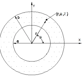
Fig. 1: A thick cylindrical vessel
Fig.1 shows a thick FGM cylindrical vessel of inside radius a and outside radius b. The properties in
z
and
directions are identical. The material of the vessel is graded in the radial direction so that the properties of the material, modulus of elasticity, thermal expansion coefficient and thermal conductivity, become functions of r. Therefore, the following different power law functions of radius in the radial direction are considered,1 2
1
1
,
n n
r
r
E
E
andk
k
1r
n3 (1)where E1,
1 and k1 are material constants for modulus of elasticity E, thermal expansion coefficient
and thermal conductivity k & n1, n2 and n3 are power indices of the material, respectively.2.1. Heat transfer problem
Under the steady-state condition, the heat conduction equation for the unidirectional cylindrical co-ordinate and the third kind boundary conditions for a thick cylindrical vessel, made of functionally graded material, is given by,
1
0
dr
dT
rk
dr
d
r
(2)
where T = T(r) is the temperature at any position of r.
h
1T
q
1dr
dT
k
r a
r a
andh
2T
q
2dr
dT
k
r b
r b
(3)
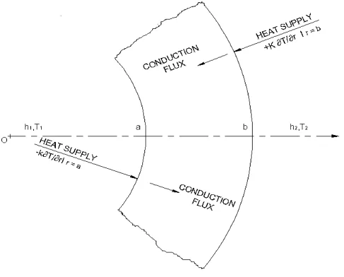
Fig. 2: Cylindrical element of heat conduction
where q1
h1T1
and q2
h2T2
are constants for given heat transfer co-efficient and temperature of inside fluids of the vessel and for given heat transfer coefficient and temperature of outside fluid of the vessel, ka and kb are thermal conductivities at r = a and b, respectively. Similarly, Taand Tbare temperatures at r = a and b, respectively.Substituting Eq. (1) for k into Eq. (2), the equation becomes,
3 1
0
dr
dT
r
dr
d
n(4)
Integrating Eq. (4) twice produce for
n
3
0
,T
C
1ln
r
C
2 (5)and for
n
3
0
,3 4 3
C
r
C
T
n
(6) By use ofBoundary conditions from Eq. (3), the constants C1, C2, C3and C4 become,
122 12 1 22 11 1 21 12
2 12 1 22 1
ln
ba
C
C
a
C
C
b
C
C
q
C
q
C
C
(7)
1
22 12 1 22 11 1 21 12
12 1 11 2 22
1 21 1 2
ln
ln
ln
ba
C
C
a
C
C
b
C
C
a
C
a
C
q
b
C
b
C
q
C
(8)
3 3
3 3
12 1 11 3 22 22
1 21 3 12
2 12 1 22
3 n n n n
a
C
a
C
n
C
b
C
b
C
n
C
q
C
q
C
C
(9)
3 3
3 3
3 3
3 3
12 1 11 3 22 22
1 21 3 12
12 1 11 3 2 22
1 21 3 1
4 n n n n
n n
n n
a
C
a
C
n
C
b
C
b
C
n
C
a
C
a
C
n
q
b
C
b
C
n
q
C
where 3 3 1 21
1 12 1
11
,
,
n b n
a
k
a
C
h
C
k
k
b
k
C
andC
22
h
2, based on the boundary conditionsshown in fig. 2.
2.2. Stress- strain-displacement relationships
As the properties in z and
directions are identical and the symbol udenotes the displacement in the radial direction, the strain-displacement relationships become,
dr
du
r
and
r
u
(11) and the corresponding thermo-elastic stress-strain relationships become ,
G
T
G
e
rr
2
3
2
and
e
2
G
3
2
G
T
(12)where r and
r are the stress and strain in radial direction and θ and
are the stress and strain in tangentialdirection, T is the rise in temperature with respect to temperature where stress values in the material is zero if the cylindrical vessel is undeformed, e, the dilatation , =
r
,
for plain strain condition and and G are Lame’s elastic coefficients related with the modulus of elasticity E and Poisson’s ratio by:
2
1
1
E
and
1
2
E
G
(13)2.3. Equilibrium equation and solution
Neglecting the body force and the inertia, the equilibrium equation becomes
0
dr
d
r
rr
(14)To convert Eq. (14) into displacement term, the functional relationship of the properties of the material should be used.
By use of Eq. (1), (5), and (11) through (13) into Eq. (14) results the Navier equation for
n
3
0
,2 1 1 1 1
2
2 2
ln
2Pr
Ru
X
r
nr
Y
r
ndr
du
Qr
dr
u
d
(15)
and again by use of Eq. (1), (6), (11) through (13) into Eq. (14) results the Navier equation for
n
3
0
,2 2 1 2 1
2
2 2 3 2
Pr
Ru
X
r
n n
Y
r
ndr
du
Qr
dr
u
d
(16)
where
2 1 1 4 2 3
2 1 1 3 2
2 1 2 1 1 1 2 1 1 1 1
1 1
,
, ,
, 1
1 ,
1 ,
1 1
n n C andY n
n n C X
n n C C Y
n n C X
n P R n P Q P
(17)
The general solution of Eq. (15) and (16) which are non-homogeneous differential equations, are obtained by adding a particular solution of Eq. (15) and (16) to the complementary function of the homogeneous form of Eq. (15) and (16).
and substituting this into homogenous forms of Eq. (15) and (16) result,
Ps 2
Q P
s R 0 (19) where P, Q, R are obtained from Eq. (17).Eq. (19) has two roots,
P
PR P
Q Q P s
2
4 2 2
, 1
(20)
Therefore, the complementary functions are for
n
3
0
1 2 2 1s s
c
r
A
r
A
r
u
(21)and for
n
3
0
1 2 4 3s s
c
r
A
r
A
r
u
(22)The particular solution up
r is considered for Eq. (15) in the form of
1ln
2
n21p
r
B
r
B
r
u
(23)and for Eq. (16) in the form of
3 n2n3
4 n21p
r
B
r
B
r
u
(24)Substituting Eq. (23) into Eq. (15) and Eq. (24) into Eq. (16) and equating the corresponding coefficients of identical powers yield
Pn
Q
n
R
X
B
1
2 2
1
1 (25)
22 2
2 1 2
2 1 2
1
1
2
1
R
n
Q
Pn
Q
n
P
X
R
n
Q
Pn
Y
B
(26)
R
n
n
Q
n
n
P
X
B
1
3 2 3
2
2
3 (27)
and
R
n
Q
Pn
Y
B
1
2 2
2
4 (28)
where P, Q, R, X1, Y1, X2and Y2 are obtained from Eq. (17). The general solution for u(r) is
u
r
u
c
r
u
p
r
(29) Therefore, forn
3
0
,
u
r
A
1r
s1
A
2r
s2
B
1ln
r
B
2
r
n21 (30)and for
n
3
0
,
u
r
A
3r
s1
A
4r
s2
B
3r
n2n31
B
4r
n21(31)
Substituting Eq. (30) into Eq. (11), the strains are obtained as
1 2
21 2
2 1
1 2 2 1 1
1
ln
1
n s
s
r
s
A
r
s
A
r
B
r
B
n
B
r
and
1 2
22 1 1 2 1 1
ln
n s sr
B
r
B
r
A
r
A
(33)Again substituting Eq. (31) into Eq. (11), the strains are obtained as
1 2
1
2 3
1
22 4 3 2 3 1 4 2 1 3 1 n n n s s
r
s
A
r
s
A
r
B
n
n
r
B
n
r
(34)and
1 2 2 3 2
4 3 1 4 1 3 n n n s s
r
B
r
B
r
A
r
A
(35)Now substituting Eq. (32), (33) and (5) into Eq. (12), the stresses are obtained as
r
r
C
n
n
B
r
C
n
n
B
B
r
s
A
r
s
A
E
n n n n s n s n rln
1
1
1
1
1
1
1
2
1
1
2 1 2 1 2 1 1 1 1 1 2 2 1 1 2 2 2 2 1 1 2 2 1 1 1 1
(36)and
r
r
C
n
n
B
r
C
n
n
B
B
r
s
A
r
s
A
E
n n n n s n s nln
1
1
1
1
1
1
2
1
1
2 1 2 1 2 1 1 1 1 1 2 2 1 1 2 2 2 2 1 1 2 2 1 1 1 1
(37)Again substituting Eq. (34), (35) and (6) into Eq. (12), the stresses are obtained as
3 2 1 2 1 2 1 1 1 1 3 3 2 3 2 3 1 4 2 2 4 1 2 4 1 1 3 11
1
1
1
1
1
2
1
1
n n n n n s n s n rr
C
n
n
n
n
B
r
C
n
n
B
r
s
A
r
s
A
E
(38)and
3 2 1 2 1 2 1 1 1 1 3 3 2 3 1 4 2 4 1 2 4 1 1 3 11
1
1
1
1
1
2
1
1
n n n n n s n s nr
C
n
n
B
r
C
n
B
r
s
A
r
s
A
E
(39)The mechanical boundary conditions at inside and outside surfaces are considered to find out the constantsA1,A2,A3and A4,from Eq. (36) and (38). The boundary conditions are:
r|
ra
p
i and
r|
rb
p
o (40) where piand po are the internal and external fluid pressures respectively.Let,
1
1
2
1
E
K
,
r
r
C
n
n
B
r
C
n
n
B
B
K
n n n nln
1
1
1
1
1
2 1 2 1 1 1 2 2 1 1 2 2 2 2 1
3 2 1 2 1 1 3 3 2 3 2 3 1 4 2 2 41
1
1
1
n n n n nr
C
n
n
n
n
B
r
C
n
n
B
K
(42)Again,
1
1
1,
1
1 1
n sa
K
s
a
2
1
2
n1s21,
a
K
s
a
11 1
1 1
1
n sb
K
s
b
and 2
1
2
n1s21b
K
s
b
(43)
p
i
a
Z
iand
p
o
b
Z
o (44)
p
i
a
Z
i and
p
o
b
Z
o (45)where
a
|
ra,
b
|
rb,
a
|
ra, and
b
|
rb.
So, The values of constants
A
1,A
2A
3andA
4are: 1 2 2 1 2 2 1 b a b a o a ib
Z
Z
A
and 1 2 2 1 1 1 2 b a b a i b oa
Z
Z
A
(46) 1 2 2 1 2 2 3 b a b a o a ib
Z
Z
A
and1 2 2 1 1 1 4 b a b a i b o
a
Z
Z
A
(47)3. Validation
The general solution of the functionally graded thick cylindrical vessel is furnished in section 2. In the final equations if one substitutes zeroes for the indices n1, n2, n3, he should get the expressions for an isotropic and homogenous vessel. This fact can be used as a partial validation of the final Eq. (36) and (37).
Substituting n1 = n2 = n3 = 0 in Eq. (1); E,
and k become E1,
1 and k1, which are modulus of elasticity, thermal expansion coefficient and thermal conductivity respectively for an isotropic and homogeneous material. From Eq. (20), (7), (8), (25), (26) and (46) one obtainss1 = 1, s2 = -1,
, ln ln ln , ln 2 1 a b a T b T C a b T T C b a b a , 0 , ln 1 1 2 1 2 1 1 B a b T TB a b
, ln ln 2 1 ln ln 1 1 ln 1 2 1 2 1 1 2 2 2 2 2 2 1 2 2 1 2 2 1 a b a b a b a b T T T b a b T T a b E b p a p A b a b b a o i
and
2
2
2 2 1 2 2 1 2 2 2 1 2 1 1 a b b a T T a b E p p b a
A i o a b
,
where
T
a
T
|
raand
T
b
T
|
rb.
Substituting above values into the general analytical solution in Eq. (36) and (37), as specified in section 2, reduce to
a b r b a b a r b a b T T E a b r b a p p a b b p a p b a o i o i r ln 1 ln ln 1 2 2 2 2 2 2 1 1 2 2 2 2 2 2 2 2 2
(3.1)
and
a b r b a b a r b a b T T E a b r b a p p a b b p a p b a o i o i ln 1 ln 1 ln 1 2 2 2 2 2 2 1 1 2 2 2 2 2 2 2 2 2 (3.2)From reference [Chakrabarty(1998), Noda et al.(2003)] one can easily verify that
Eq. (3.1) and (3.2) are indeed the expressions for radial and tangential stresses for an isotropic and homogeneous thick cylindrical vessel.
4. Results and discussions
A numerical solution for the general solution deduced in section 2, is presented by an example assuming the power index for the modulus of elasticity, the thermal expansion coefficient, and the thermal conductivity to be same (n1 = n2 = n3 = n).
the tangential stresses for thermal, mechanical and thermo-mechanical loads are separately treated in figs. 3 through 9. A study of the Tresca yield stress (
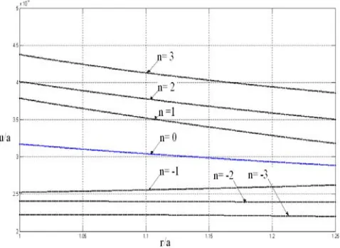
r) is made to check for yielding in fig.10.4.1. Radial displacements
Radial displacement, u(r) increases as n increases for thermo-mechanical loads
(fig. 3). u(r) gradually decreases for n
0 and gradually increases for n
-1 in the radial direction, from inside surface to that of outside for thermo-mechanical loads.4.2. Radial stresses
The radial stress,
r increases as n increases for thermal load (fig. 4),
rdecreases as n increases for mechanical load (fig.5) and
rdecreases as n increases for thermo-mechanical loads (fig. 6).4.3. Tangential stresses
Tangential stress,
gradually increases for stress < 0 and
gradually decreases for stress > 0 as n increases for thermal load (fig. 7). Stresses vary compressive to tensile in the radial direction, from inside surface to outside.
gradually decreases for n < 1 and
gradually increases for n > 1 in the radial direction, from inside surface to that of outside for mechanical load (fig. 8). However, for n = 1,
varies little in the radial direction, from inside surface to outside. Stresses are tensile in nature.
gradually decreases for n
0 and
gradually increases for n
1 in the radial direction, from inside surface to that of outside for thermo-mechanical loads (fig. 9). Stresses are tensile in nature. However, for n = 0.7,
varies little in the radial direction, from inside surface to outside.
4.4. Tresca yield criterion
The stress, (
r), gradually decreases for n
1
and gradually increases forn
2
in the radial direction, from inside surface to that of outside for thermo-mechanical loads. However, (
r) is about to be uniform in the direction of radius for n = 1.5. The stress,(
r) exceeds the yield strength for n
0
at inside surface and exceeds the yield strength for n
3
at outside surface, with the consideration here that the yield strength does not vary for the functionally graded material. Stresses are tensile in nature. However, for n = 2, the stress varies little in the radial direction.Fig.4: Radial stress for thermal load
Fig. 5: Radial stress for mechanical load
Fig. 7: Tangential stress for thermal load
Fig. 8: Tangential stress for mechanical load
Fig. 10: Tresca stress for thermo-mechanical loads
5. Conclusions
The analysis is done and studied with the following points:
(1) In this work, a direct method is presented which does not exhibit any ambiguity to consider the third kind thermal and general mechanical boundary conditions.
(2) For the power index, n3= 0, the variation of temperature follows the logarithmic-law of radius. (3) The radial displacement increases for thermo-mechanical loads, as the power index n increases causing
expansion to the vessel.
(4) The radial stress increases for thermal load, decreases for mechanical load and decreases for thermo-mechanical loads, as n increases.
(5) Vessel subjects to thermal load, the radial stresses become compressive for all power indices. (6) Tangential stress varies compressive to tensile for thermal load, from inside surface to outside. (7) For n
0, the tangential stress gradually decreases and for n
2, gradually increases in the radialdirection, from inside surface to that of outside when the vessel subjects to mechanical load. However, for n = 1, the stress varies little in the radial direction and sets up tensile stresses.
(8) For n
0, the tangential stress gradually decreases and for n
1, gradually increases in the radialdirection, from inside surface to outside for thermo- mechanical loads and sets up tensile stresses. However, for n = 0.7, the stress varies little in the radial direction
(9) The vessel exceeds the yield strength for n
0
at inside surface and exceeds the yield strength for n
3
at outside surface, with the consideration here that the yield strength does not vary for the functionally graded material. Stresses are tensile in nature. However, for n = 2, the stress varies little in the radial direction. (10)As the stresses vary from inside surface to outside, by the proper gradation of the material of the planarisotropy with non-homogeneity in the radial direction, gives better result compared to the autofrettaged and multi-layered cylindrical vessel.
References
[1] Chakrabarty J. (1998): Theory of Plasticity. McGraw Hill, New York.
[2] Delfosse D.; Cherradi N.; Ilschner B. (1997): Numerical and experimental determination of residual stresses in graded materials. Composites, part B, (28B), pp. 127-141.
[3] Kieback, B.; Neubrand, A.; Riedel, H. (2003): Processing techniques for functionally graded materials. Material science and engineering, Part A, (A362), pp. 81-105.
[4] Koizumi, M. (1997): FGM activities in Japan. Composites, part B, 28B, pp. 1-4.
[5] Lutz M. P.; Zimmerman R W. (1996): Thermal stresses and effective thermal expansion coefficient of a functionally graded sphere. Thermal stress, 19, pp. 39-54.
[6] Noda, N.; Hetnarski, R. B.; Tanigawa, Y. (2003):Thermal Stresses. Taylor and Francis, New York.
[7] Tutuncu, N.; Ozturk, M. (2001): Exact solutions for stresses in functionally graded pressure vessels. Composites, part B, 32, pp. 683-686.
[8] Ozisik, M. N. (1985): Heat Transfer. McGraw Hill, New York.