Effect of Different Mold Layers on Fly Ash
Modified Ceramic Shell Strength In
Investment Casting.
1Prof.D.D.Shukla
1
VicePrincipal and Head of Department Mechanical Engineering
Atmiya Instittue of Technology And Science for Diploma Studies Kalawad Road,Rajkot-360005,Gujarat, India
2
Dr.J.L.Juneja 2
Principal
Ahmadabad Institute of Technology
Nr.Vasantnagar Township, Gota Ognaj Road,Ahmedabad-380060,Gujarat, India Contact address: E-112, Raviratna Park, Street No.4, University Road, Rajkot-360 005
Abstract :
Shell formulation plays vital role on shell strength. A well defined shell room process and control environment can produce uniform shell with sufficient strength. To monitor and control slurry consumption is also important as cost point of view. Cost saving in slurry without compromising shell strength should be the goal of shell room. Feasibility of fly ash as an alternate ingredient for shell building studied and it’s effect on shell strength checked by using different numbers of layers.
Keywords: Ultimate stress at fracture point, deflection, zircon, Fly ash, mold layers
1. Introduction
Investment casting depends on the good quality of ceramic shell in order to produce sound castings. Quality of the Ceramic shells is dependent on shell room process parameters. Production of Good Shell without any defect largely depends on: Properties of the Wax, Shell Formulation, De-waxing Process and Mold Handling etc.[Schiefelbein (1989)].
This work was carried out specifically to determine the effect of fly ash on ceramic shell strength.Feasibility of fly ash as an alternate ingredient for shell building studied and it’s effect on shell strength checked by using different numbers of layers.
Fly ash is available in huge quantity, Disposal of tons of fly ash every year is a biggest problem faced by all the thermal power plants. Now a day’s Fly ash is widely utilized by construction industries and for land filling purpose. Investment casting industries consumes large amount of slurry for shell formation. Here fly ash as one of the ingredients to slurry used and its potential usage in this new area is studied. Effort of work in this direction may be helpful to reduce global world pollution problem.
2. Material Selection
There are many factors affecting shell cracking the subject of shell material selection becomes Important. A list of the commonly used refractory is Zircon, Aluminosilicates, Fused Silica, Quartz and Tabular and Fused Alumina. Many of these products are available in sized grades from fine flours to coarse stuccos.All of the materials commonly used may be formulated to produce shells with adequate strength [Feagin (1978)].
3. Slurry Formulation
The preceding quote from G.W. Schiefelbein, during a symposium on shell cracking, It states that the task facing the Investment Casting Shell Room is to:
“…process the shell so it will survive the stresses that cause cracking.”
Shell room process control is critical to the production of quality shells. Shell room process control encompasses many important issues but it must begin with the proper mixing of slurries. Proper slurry building techniques eliminate many common slurry problems.
Slurry mixing has a effect on the strength of the shell. A poorly wet-in slurry will not develop it’s maximum strength potential. Slurries are in a constant state of change. Slow moving slurries age and deteriorate, while slurries that are used and replaced change with each addition of new slurry [Roberts (1977)].
Evaporative losses must be replaced to maintain silica levels in all slurries and pre-wet tanks. Most foundries are aware that the control of silica solids and pH levels is critical to the proper functioning of a binder and its associated slurries [Rusher (1975)].
Control of slurries should not be limited to testing and managing silica solids and pH levels, other characteristics of slurry should be monitored and controlled as well.
Precoat slurry was prepared using Zircon flour-37.5Kg,Colloidal Silica-70Kg,Dioctyl Sodium Sulphosuccinate (aerosol OT-C20H37NaO7S)-5ml, n-OctylAlcohol (Octanol-C24H38O4)-2.5 ml, Dimineral water-0.5 Lit.Viscosity reading was taken with Zahn #4 cup and it was between 80 to 95.Precoat slurry formulation was not disturbed because it decides surface configuration and accuracy of dimensions.
Back up slurry was prepared using Fused Silica (30/80 Grade)-100 Kg, Dimineral water-3 Lit
.,
and Final slurrywas prepared using Fused Silica (16/30 Grade)-65 Kg,Colloidal Silica-60 Kg and Dimineral water-3 Lit
.
In a new slurry formulation fly ash was added in backup slurry and final slurry. Fly ash addition was done with reference to weight % of slurry and it was found after several trials that addition can be done in the range of 2 to 4%, beyond this limit slurry becomes difficult to handle. Fly ash was added in both back up and final slurry
4. Shell Room Process Control
Ceramic shell strength depends on slurries and shell room environments control. A ceramic shell process under control involves more than monitoring and controlling temperature, humidity and slurries. Dipping techniques, stuccoing sequences, air movement programs, and drying times should be recognized as part of ceramic shell process.
5. Materials and Methods
The materials used in this study were standard products: Zircon flour, Colloidal Silica, Dioctyl Sodium Sulphosuccinate (aerosol OT)- C20H37NaO7S, n-Octyl Alcohol(Octanol)- C24H38O4, Dimineral water and Fly ash To check Ceramic shell strength various test bars were prepared from one leading foundry involved in investment casting manufacturing, modulus of ruptures were measured with help of 3-point bend method at CGCRI(Central Glass and Ceramic Research Institute),Ahmedabad. Total 06 nos. of Shell Tree were prepared with 10 to 12 test bars of standard size (5 to 8 ‘’ length,1’’ wide and ¼’’ thick)And formula (3WL)/ (2bd2) used for MOR calculation where, W=Load,L=Span,b=Width,d=Thickness. All 06 Shell trees were coded like OST(Original shell tree),2FAST(2%Fly ash shell tree),3FAST(3%Fly ash shell tree), 4FAST(4%Fly ash shell tree), 5L3FAST(5Layer 3%Fly ash shell tree)and 7L3FAST(7Layer 3%Fly ash shell tree).
6. Experimental set up
Various samples were prepared from one of the leading foundry as per their routine dipping sequences. All samples were cut to rectangular strip shape to test it’s MOR (modulus of Rupture).
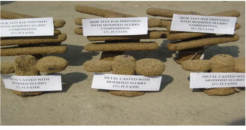
Fig.1.1 Tree prepared with 2, 3 and 4% Fly ash
Table 1.1 Modulus of Rupture of shells prepared with 2, 3 and 4 % fly ash
TEST
BAR
MOR (Kg/Cm2)
2FAST 3FAST 4FAST
1 6.9107 8.2036 5.1026
2 5.2862 8.3392 4.6509
3 9.7248 6.1730 6.5560
4 7.6954 8.0350 3.6604
5 6.1546 10.7997 7.7907 6 13.5870 9.0646 5.4529
7 5.5928 5.4888 5.7980
8 6.3743 6.8672 5.0397
Average 7.6657 7.8714 5.5064
Table 1.2 Weight calculation
Experiment No.
Shell Name
Average weight of test bar per tree
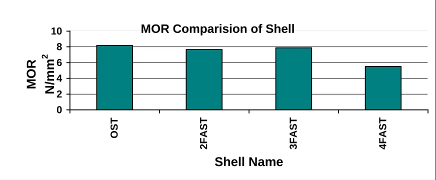
MOR Comparision of Shell
0 2 4 6 8 10 OST2FAST 3FAST 4FAST
Shell Name
MOR
N/
mm
2
Fig.1.2 MOR comparison of shell
Weight Comparision of Shell
0 20 40 60 80 100 120 140 160 180 OS T 2F A S T 3F A S T 4F A S T Shell Name W e ight g m s .
Fig.1.3 weight comparison of shell
Table 1.3 Hardness calculation
Hardness (HBN)
Sample 1 2 3 4 Average Original 43 38 40 40 40.25 2% Fly Ash 44 45 39 41 42.25 3% Fly Ash 46 42 42 40 42.5 4% Fly Ash 43 41 40 42 41.5
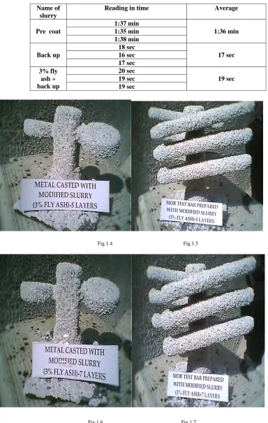
Table 1.4 Density calculation
Name of slurry
Reading in time Average
Pre coat
1:37 min
1:36 min 1:35 min
1:38 min Back up
18 sec
17 sec 16 sec
17 sec 3% fly
ash + back up
20 sec
19 sec 19 sec
19 sec
Fig.1.4 Fig.1.5
Fig.1.6 Fig.1.7
5L3FAST Shell was prepared with application of 5 layers of slurry coating sequences were 1 Pre-coat slurry,2 coats of Backup slurry/Regular,2 coats of 3% Fly ash plus Original slurry.
7L3FAST Shell was prepared with application of 7 layers of slurry coating sequences were 1 Pre-coat slurry,2 coats of Backup slurry/Regular,4 coats of 3% Fly ash plus Original slurry
Table 1.2 and 1.3 shown below shows MOR Readings for 5 Layer of 3% Fly Ash Shell (5L3FAST) and 7 Layer of 3% Fly Ash Shell (7L3FAST).
Table 1.5 MOR reading for 5L3FAST
Shell Name-5L3FAST (5 Layer of 3% Fly Ash Shell) Average Sample W L b d MOR N/mm2 kg/cm2
1 1.51 130 37.07 4.7 0.35958
0.5984 6.1004 2 4.53 130 37.99 4 1.4532
3 1.51 130 36.01 4.3 0.4422 5 1.51 130 36.48 3.9 0.5306 6 1.51 130 36.94 4.9 0.3319 7 1.51 130 37.04 4.1 0.4729
Table 1.6 MOR reading for 7L3FAST
Shell Name-7L3FAST (7Layer of 3% Fly Ash Shell) Average Sample W L b d MOR N/mm2 kg/cm2
1 9.063 130 40.81 6 1.202922
0.8971 9.1458 2 9.063 130 40.4 6.4 1.067985
3 7.552 130 40.42 6.1 0.979131 4 9.063 130 39.97 7 0.902353 5 7.552 130 41.92 6.1 0.944095 7 7.552 130 40.5 6.3 0.916137 8 6.042 130 39.96 7.1 0.584889 9 6.042 130 40.3 7.1 0.579954 7. Results and discussion
Correctness of all experimental results were verified and certified by central government research laboratory, Central Glass and Ceramic Research Institute (CGCRI), Ahmadabad and metallurgical laboratory of M.S.University, Baroda.
8. Conclusion
The reduction of shell cracking by building optimum green strength into a ceramic shell requires the selection of the proper materials, followed by their consistent and proper use. Consistency in their use requires that the processes at work be defined and controlled.
Define proper procedures for the production of MOR bars and establish test cycles to develop historical information on shell and identify trends.
This work was carried out specifically to check the feasibility of fly ash as an ingredient to shell slurry and to determine the effect of layers on shell strength.
As amount of fly ash increased the slurry became solid like cement. Curing became faster on addition of fly ash. We can say from test result that there is no major change in strength of shell but as moving on higher percentage side shell strength decreased. Cost point of view fly ash is the cheapest material freely available in huge quantity, so in this paper we tried to check the possibility of it’s usage to decrease shell cost with out affecting quality of casting.
References
[1] G.W. Schiefelbein -“Controlling Ceramic Shell Cracking”, in Investment Casting Institute’s (eds.), Shell Cracking Symposium – Proceedings, Birmingham, Alabama, May 1 -3, 1989, p.p 11.
[2] C.Feagin- “Characteristics of Some Aluminosilicates – Colloidal Silica Shell Systems”, 26th Annual ICI Meeting, October 5, 1978, p.p 32
[3] Bill Roberts- “Factors Affecting Shell Strength”, 25th Annual ICI Meeting, October 7, 1977, p.p 25.