3D COLOR OBJECTS RECOGNITION
SYSTEM USING AN ARTIFICIAL
NEURAL NETWORK
Omar BENCHAREF, Mohamed FAKIR, Brahim MINAOUI
Moulay Slimane University - Sciences & Techniques Faculty - Computer science department Information processing and telecommunication team
[email protected];[email protected];[email protected]
B.BOUIKHALEN
Moulay Slimane University - Multidisciplinary Faculty - Mathematic department Information processing and telecommunication team
Abstract:
Hu & Zernike moments have always been used for grey image representation. In this study we have tried to employ them directly for color image description. This would enable us to keep the maximum amount of information given by the image colors. Regarding the classification process we have opted for the neural networks classifier, which enable to implicitly detect complex nonlinear relationships between dependent and independent variables, and to detect all possible interactions between predictor variables, and the availability of multiple training algorithms. In this document, we present a comparative study between different 3D color objects recognition systems. We have used a variety of topologies of Neural Multi-layer Networks (simple, nested and parallel networks), to come up eventually with a suggestion of a multi-Oriented Neural Networks.
Keywords: Neural Network; Zernike moments; Hu moments; 3D object recognition ; Coil-100 Data Base.
1. Introduction
Recently, computer vision has become one of the most appealing domains of research. Object Recognition stands for one of the main pillars of this science.
In the classic pattern of shape recognition process we list two major steps feature extraction and classification.
• Feature extraction is a special form of size reduction, which involves simplifying the amount of resources, required to describe a large set of data accurately .When the input data of an algorithm is too large to be processed and it is suspected to be notoriously redundant. Different techniques have been used [1] [11] [5], but the most commonly used are the forms descriptors [4] [7].
• Image classification methods can be divided into two broad families of approaches:
o Learning-based classifiers, which require an intensive learning/training phase of the classifier parameters (e.g., parameters of Support Vector Machines decision trees [A. Bosch 2007], fragments and object parts [6] and Neural Network. These methods are also known as parametric methods.
o Nonparametric classifiers, which base their classification decision directly on the data, and require no learning/training of parameters (Nearest-Neighbor distance estimation) [2].
Given the complexity of processed data (color objects), we chose Neural Network on the subject of their ability
2. Image Acquisition
Extraction Process
The importance of invariance in computer vision has been identified in the 60’s. However, the vision algorithms by computer based on invariants have become more popular recently and they stand for an active area of research [8] [9]. This section emphasizes two types of invariant descriptors.
3.1.Zernike moments
The Zernike polynomials were made-up in 1934 by Zernike. These moments are used for their characteristics:
o Reduction of noise. o Invariance to rotation. o Reducing redundancies
The Zernike moment is a series of calculations that transforms an image into vectors with real components representing the Aij moments.
The geometrical moment of a function f(x,y) is by definition the projection of this function on the polynomials space denoted by xpyq (p,q)
∈
N2. However, the considered space is not generally orthogonal whichreduces the control of redundancy that would appear during the projection.
Therefore, Zernike had introduced a set of complex polynomials which form an orthonormal basis defined inside the unit circle, which means for
x
2+
y
2≤
1
.The polynomial is defined as follow:
(1)
With:
n: a positive integer (or null)
m: an integer with |m|<=n
r : the vector length (distance between the origin and the pixel) (x,y)
θ: Angle formed by vectors p and x
Rnm : radial polynomial
V*(x,y) : complex polynomial, which is the projection of f(x,y) on the complex polynomials space. Such polynomials are indeed orthogonal :
[
*( )
,]
. ( , ) 0 1 12 2
or dxdy
y x V y x Vnm pq y
x
=
<= +(2)
The Zernike geometrical moment is the projection of a function f(x,y) describing an image on orthogonal
Fig.1: Objects from Coil-100 database
( )
,
( )
,
(
).
exp(
)
*
ρ
θ
ρ
θ
jm
R
V
y
x
V
nm=
nm=
nmpolynomials space
(
,
)
*ρ
θ
nmV
: (3)Regarding the identification, we use the absolute value of Zernike Moments:
A
nm=
Re
2(
A
nm)
+
Im
2(
A
nm)
(4)3.2. Hu moments.
Let I(x,y) is the grey level of one pixel of image I, the moment [16] of (p + q) order (p; q > 0) of an image I is denoted:
(5)
The centroid (
x
0,
y
0) of the function I is given by (x0 = m1,0 / m0,0 , y0 = m0,1/m0,0). The centered image IT (x, y) = I (x + x0, y +y0) is invariant under translation.The central moment of order (p + q) of the function I is given by:
v
x
y
qI
x
x
y
y
dxdy
R p q
p;
(
0,
0)
2
+
+
=
(6)The central moments are invariant. The normalized moment is defined as follow:
γ
ν
ν
μ
0 , 0 , , q p qp
=
(7)Where:
γ
=
1
+
(
p
+
q
)
/
2
These moments are invariants under translation, rotation and scaling. The moments of Hu are calculated via the normalized moments and they remain invariant under translation, rotation or scaling:
. ) 3 ( ] ) ( 3 . . ) )[( )( 3 ( ) ( ) ( ) 3 ( ) 3 ( 4 ) ( 2 3 , 0 1 , 2 2 3 , 0 1 , 2 2 2 , 1 0 , 3 2 , 1 0 , 3 2 , 1 0 , 3 5 2 3 , 0 1 , 2 2 2 , 1 0 , 3 4 2 3 , 0 1 , 2 2 2 , 1 0 , 3 3 2 1 , 1 2 2 , 0 0 , 2 2 2 , 0 0 , 2 1
μ
μ
μ
μ
μ
μ
μ
μ
μ
μ
φ
μ
μ
μ
μ
φ
μ
μ
μ
μ
φ
μ
μ
μ
φ
μ
μ
φ
− + + − + + − = + + = − + − = + − = + = (8) 4. ClassificationClassification is the process in which features computed in features extraction phase are used by the classifier to map the object into proper object classes.
In pattern recognition field, artificial neural network based classifier appears to be the most general and less
dxdy
V
y
x
f
n
A
x y nm nm
+
=
1
(
,
).
*(
ρ
,
θ
)
π
dxdy
y
x
I
y
x
m
q R p qp
(
,
)
2
cumbersome, with
• Simple processing elements • A high degree of interconnection • Simple scalar messages
• Adaptive interactive between elements
The Artificial Neural Network (ANN) was inspired by investigations into the structure of the human brain that consists of interconnected neurons. An ANN is made up of interconnecting artificial neurons within input, hidden and output layers. It has two modes of operation: training mode and operation/testing mode. In the training mode, neurons are trained using a particular input pattern to produce the desired output pattern. In the operation/testing mode, when a taught input pattern is detected at the input, the ANN will produce its associated output.
A Back propagation or feed-forward Back propagation ANN consists of two processing parts within its neurons: forward and backward. When an input pattern is fed to the ANN during its training process, the ANN will try to learn and compare its predicted output value with the desired output value. The errors between the predicted and actual valued are then ``back propagated'' through the network, and a gradient descent algorithm used to adjust the weights in the hidden and output layer nodes. The result is a network that produces the mapping between the input values and the output values via the neurons. [10]
4.1. Recognition of color objects (Classic method)
The common method consists of using the Zernike & Hu moments on binary images to identify their geometrical shape first, and then a color function is used in order to define their colors.
4.1.1 Zernike & Hu on binary images
The Zernike or Hu moments are applied on binary images where the function f (x, y) can be equal to 1 or 0 (fig.3).
Fig.3 Binary representation
4.1.2 Zernike & Hu on images of color function
To differentiate objects that have the same shape, we generally apply the moments of Zernike to color images where the function f (X, Y) (equation 9) is the level of gray of the pixel, to which is added the average of colors components RGB (Red, Green, Blue)[9].
B
B
R
y
x
f
(
,
)
=
0
.
3
+
0
.
6
+
0
.
1
(9)
4.1.3 Disadvantages of the classic method
In practice, this method has two major disadvantages in the 3D objects recognition process (Fig.4 and Fig.5). When the image is seen from different angles of view, objects might be confused in their binary form. Fig. 4 shows an example of such situations.
4.2.Suggested methods for color object recognition
4.2.1 Zernike or Hu moments on color pictures
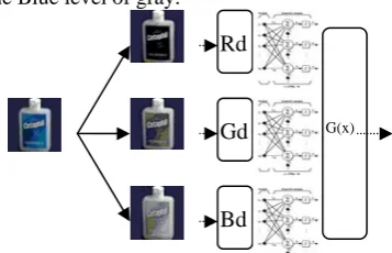
Normally, recognition methods based on shape descriptors are applied on binary pictures as well as on gray pictures. The alternative approaches use the moments of Zernike & Hu in parallel on the three levels of gray RGB, this will result in maintaining maximum information concerning color (Fig.6).
4.2.2 Zernike & Hu in parallel
We calculate the moments of Zernike & Hu for every level of gray. For the classification, we use three Back propagation Neural Networks in parallel for every level of gray (Fig.7). Three level of grey used are the following:
Rd: Zernike or Hu moment of the Red level of gray. Gd: Zernike or Hu moment of the Green level of gray. Bd: Zernike or Hu moment of the Blue level of gray.
The output of the three ANN is given by the function G given by G(X))=max(Xi) With
X
i=
x
i1+
x
i2+
x
i3 for i = 1 to n where :a) b) c)
Fig.6: Extraction of the ttree levels of graya) original image, b) gray levels, c) Extraction of Zernike & Hu moments
1.07 1.4 … 0.43
3.14 2.01 … 1.51 1.34 1.34 … 1.43
Fig. 4 : The conversion into binary gives an inc omplet e representa tion of the object
Fig. 5: Loss of information
Rd
Gd
Bd
G(x)
xi1 is the i output of the first NN .
xi2 is the i output of the second NN.
xi3 is the i output of the third NN.
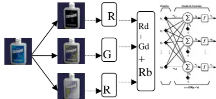
4.2.3 Zernike & Hu moments in series
We calculate the moments of Zernike & Hu for every level of gray and we take the first n moments of every level and put it in a set to form a unique input of the Back propagation Neurons Network .(Fig. 8)
4.2.4 N.N in series with color & shape detection
This network Fig. 9 uses the same technique of the N.N in series and provides additional results. Besides to the recognition of objects, other outcomes of this N.N are the shapes and the colors of those objects. This additional information allows getting correct results when two or more objects are confused.
With:
Od: Outputs concerns the object recognition. Cd: Outputs concerns the color recognition. Sd: Outputs concerns the shape recognition.
Output values of Od are incremented by 15% for all objects that have the color detected.
Output values of Od are incremented by 10% for all objects that have the shape detected. And the finale output is the modified Od.
5. Experimental Results
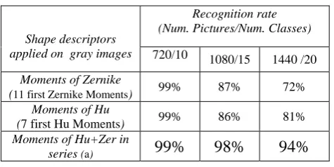
For the Object recognition part, we have tested different sizes of input pattern for the learning process. The database used here is Coil-100 (Columbia Object Image Library) database [14]. It contains 100 objects and 7200 images .The images are resized into 180x180 pixels. Some examples of original colored images are given in Fig. 1 and Fig.2. Our work is implemented using Matlab 7.4. In our experiments, we use seven Hu invariants moments while the number Zernike moments is between 9 & 60 (depends on the number of input and output data of the Neural Network). These inputs are presented to the different NN topologies presented in this paper. To choose the best object description, TABLE .1 illustrates the recognition rates obtained by using Hu, Zernike and a combination of the two descriptors moment on gray images, using a back propagation ANN.
Fig. 9 :N.N in series with color & shape detection
Rd + Gd
+
Rb
R
B
B
SdOd
Cd
Fig.8: Zernike & Hu moments in series with Back propagation Neurons Network
Rd + Gd
+
Rb
R
G
Table .I: Recognition rate obtained by using Hu & Zernike moment on gray images, (with 2 hidden layers)
Shape descriptors applied on gray images
Recognition rate (Num. Pictures/Num. Classes)
720/10 1080/15 1440 /20
Moments of Zernike
(11 first Zernike Moments) 99% 87% 72% Moments of Hu
(7 first Hu Moments) 99% 86% 81% Moments of Hu+Zer in
series (a)
99% 98% 94%
(a) we take the first 7 Zernike moments & the first 3 Hu moments .
Table 1 confirms the complementarities of Hu & Zernike moments. When they are used together the results are noticeably improved.
Concerning the rest of the experiments, we are going to use the combination of Hu & Zernike. We have tested different sizes of input pattern for the learning process. TABLE.2 & Fig.9 present the best performances obtained for each one of the NN topologies.
N.B: For the remaining experiments we used a Back propagation ANN with 2 hidden layers.
In order to verify the effectiveness and robustness of the proposed recognition system, we performed experiments on the COIL images under increasingly difficult conditions. We first considered the images exactly as extracted from the COIL database, then we added pixel-wise random noise, and an object deformation. Finally, we studied the sensitivity of the system to the luminosity change (TABLE .III).
Table .III : Recognition rate obtained by a neuron network from different alterations (2880 images /40 Classes)
Types of image IA INA Lu ID IB 10%
Recognition
Rate 99% 98% 96% 95% 98%
IA: Pictures (view Angle) presented in the Learning phase. INA: Pictures (view Angle) not presented in the Learning phase. ID: Deformed pictures. (Fig .10 )
IB: Pictures with a noisy background. (Fig.10) Lu: Luminance change (Fig.10)
.
Fig.10: object with different alterations Network Topology
Recognition rate (Num. Pictures/Num. Classes) 1440/20 2880/40 4320/60 5760/80 Simple N.N with
color function 99% 94% 87% 40%
3 N.N in parallel
for each gray level 100% 99% 90% 45% N.N in series for
each gray level 99% 98% 92% 82%
N.N in series with color & shape
detection
99% 98% 95% 89%
Table .II
Recognition rate obtained by using Hu & Zernike moment on colored images for differentN.N
l
0% 20% 40% 60% 80% 100% 120%
1440/20 2880/40 4320/60 5760/80 (Num. Pictures/Num. Classes)
Recognition rate Simple N.N with color function 3 N.N in parallel for each gray level N.N in series for each gray level N.N in series with color & shape detection
Fig.9: Recognition rate obtained by using Hu & Zernike moments on colored images for different N.N topology.
6. Conclusion
According to the results obtained by this study, we have realized that the combination of Zernike and Hu moments allow a better description of objects. Moreover, when Neural Networks are applied simultaneously with these moments the outcome was very satisfying:
- Huge reduction of apprenticeship duration.
-Significant improvement in the rate of recognition.
- Resistance to the presence of noise, deformation and to the Variation of luminance.
It is also important to mention that each of the three topologies discussed above has its own particularity: -N.N in parallel is the most suitable for small databases
-N.N in series give better results in larger databases.
-N.N in series with color & shape detection: this additional information allows getting the best results and a very good resistance to the presence of noise, deformation and to the Variation of luminance
The experimental results showed that the recognition rate of the N.N in series with color & shape detection based on Hu and Zernike moments is higher than the recognition rate of the classic method based on binary images & color function.
It is to mention the robustness of the proposed system, A rate of 89% for a big data base, formed by 80 classes of object and more than 5700 pictures.
7. References
[1] F.L. Alt, , J. ACM 9(2) (1962) 240–258. [1] F.L. Alt, “Digital pattern recognition by moments,” J. ACM February 1962 , pp. 240– 258.
[2] Oren Boiman, Eli Shechtman and Michal Irani,In Defense of Nearest-Neighbor Based Image Classification,IEEE Conference on Computer Vision and Pattern Recognition (CVPR), June 2008.
[3] A. Bosch, A. Zisserman, and X. Munoz. Image classification using random forests and ferns.In ICCV, 2007.
[4] Chee-Way Chonga, P. Raveendranb and R. Mukundan, "Translation invariants of Zernike moments", Pattern Recognition ,2003 , pp 1765– 1773.
[5] H. Dirilten, Pattern,” matching under affine transformations,” IEEE Trans. Comput. March 1977 ,pp314–317. [6] P. Felzenszwalb and D. Huttenlocher. Pictorial structures for object recognition. IJCV, 61,2005.
[7] Jan Flusser, Moment Invariants in Image Analysis ,Transaction on engineering, computing and technology February ,2006 ,ISSN ,pp1305-5313
[8] A. Khotanzad et Y.H. Hong. Invariant image recognition by Zernike moments. IEEE Transactions on Pattern Analysis and Machine Intelligence, 12(5), May 90.
[9] C.MAAOUI ‘’ Reconnaissance et détection robuste d’objets couleur ’’20th colloque GRETSI, 2005, pp :727-730
[10] SIMARD P., STEINKRAUS D., PLATT J. C., Best Practices for Convolutional Neural Networks Applied to Visual Document Analysis, ICDAR, 2003, pp. 958-962
[11] F.W. Smith, M.H. Wright, “Automatic ship photo interpretation by the method of moments,” IEEE Trans, 1971, pp1089–1095. [12] Marc Parizeau RESEAUX DE NEURONES GIF-21140 et GIF-64326 .Université de LAVAL 2006