1
Context-aware approach for formal verification
Amel Benabbou
1,*, Safia Nait Bahloul
1and Dhaussy Philippe
21LITIO Laboratory, IDTW team, University of Oran 1 Ahmed Ben Bella, BP 1524, El-M'Naouer, 31000 Oran, Algeria 2Lab-STICC Laboratory, MOCS team, ENSTA-Bretagne, France
Abstract
The Context-aware approach has proven to be an effective technique for software model-checking verification. It focuses on the explicit modelling of environment as one or more contexts. In this area, specifying precise requirement is a challenged task for engineer since often environmental conditions lack of precision. A DSL, called CDL, has been proposed to facilitate the specification of requirement and context. However, such language is still low-level and error prone, difficult to grasp on complex models and assessment about its usability is still mitigated. In this paper, we propose a high level formalism of CDL to facilitate specifying contexts based on interaction overview diagrams that orchestrate activity diagrams automatically transformed from textual use cases. Our approach highlights the boundaries between the system and its environment. It is qualified as model-checking context-aware that aims to reduce the semantic gap between informal and formal requirements, hence the objective is to assist and encourage engineers to put sufficient details to accomplish effectively the specification process.
Keywords: Context, Context-awareness, Context-aware verification, Model-checking, Model transformation, Use cases, Interaction overview diagram.
Received on 20 November 2015, accepted on 20 January 2016, published on 12 February 2016
Copyright © 2016Amel Benabbouet al., licensed to EAI. This is an open access article distributed under the terms of the Creative Commons Attribution licence (http://creativecommons.org/licenses/by/3.0/), which permits unlimited use, distribution and reproduction in any medium so long as the original work is properly cited.
doi: 10.4108/eai.12-2-2016.151085
*Corresponding author. Email: [email protected]
1. Introduction
Describing the behaviour of systems is the principle on which verification by model-checking is based. In such technique, the System Under Study (SUS) is abstracted as a model presented, generally, in the form of concurrent automata (state machine) and on which we aim to verify the correctness of requirements expressed in a formal properties language. The whole of the model behaviours (i.e., states) are explored by the model-checker to evaluate whether the specified properties are true or not. During exploring model states, the number of reachable configurations is become too large to be contained in the memory. This is known by the state explosion problem [1].
To overcome this problem, many works proposed to improve the performance of model-checkers by considering compositional verification [2, 3, 4, 5]. In this area,
context-aware verification has been introduced [6, 7] as a technique of state space decomposition that enables compositional verification of requirements. The idea is to allow to explicit separately the behaviour of entities (actors) that interact with the system and its environment. This technique reduces the set of possible spaces behaviours (and thus the state space) by considering an explicit model of the environment during its exploration. It consists to “close” the SUS with a well defined finite and acyclic environment. The reduction is based on the description of particular use cases on the environment, called contexts, with which the system interacts. The objective is to guide the model-checker to concentrate its efforts not on an exhaustive exploration of the whole model but on a relevant restriction of this latter. The formal specification of the environment enables at least three different decomposition axes: a) the environment can be decomposed in contexts; b) contexts enable the automatic partitioning of the state space into independent verification
EAI Endorsed Transactions on Context-awareSystemsandApplications 11 2015 - 022016|Volume 3 |Issue 7|e2
problems; c) the requirements are focused on specific environmental conditions in which they should be satisfied. Our work fits in this technique; we introduce an approach that is a part of a model-checking methodology for formal verification that separates contexts from functional requirements. These contexts are specified within a domain-specific language called CDL (Context Description Language) based on the concept of use case scenario [8, 9]. The behaviours are formally defined by sets of use cases which describe how the environment interacts with the SUS. Within CDL, the environment is decomposed into a set of sub-contexts which are composed separately with the SUS and on which a set of relevant properties are evaluated.
Our contribution aims to build intermediate models for the automatic generation of CDL models from manipulated artefacts. We focus particularly on the description of use cases-based contexts. The use case approach is an effective technique that allows to uncover (through scenarios) the behaviour of actors and to help focusing on their interactions with the system [10]. In the favour of our approach, use cases are transformed to a set of activity diagrams that are as well afterwards transformed into Interaction Overview Diagrams (IODs) to determinate the system boundaries. A more general type of IODs is used in second time to organize interactions according to CDL structure. The model of the SUS has to be established, producing such a model is out of the scope of this paper.
In this paper, we are concerned by two contributions: 1) The interface specification is facilitated, thanks to the transformation from use cases into IODs for each actor and using gates to relate IODs with system boundaries; 2) The orchestration of several actors and related use cases are specified by the requirements engineer using IODs that are closely related to the CDL structure and easily transformed in CDL contexts. Hence, the set of interaction diagrams together with the system model constitutes a ground model of the system that captures and fully documents the requirements and constitutes the starting point of the verification process. The paper is organized as follows. Section 2 gives an overview of CDL structure, the problem statement and objectives in section 3. Section 4 is an overall presentation of the methodology of our context-aware approach. We give our meta-models, running example, boundaries specification and orchestration aspects in section 5. Presentation of related works and comparison are intended in section 6. Finally, a conclusion closes the paper in section 7.
2. Overview on CDL language
The CDL structure is inspired from the Use Case Chart proposal [11] but extended to allow describing the entities that contribute to the environment interaction. It is hierarchically constructed in three levels: Level-1 is a set of constructs which describes hierarchical activity diagrams where either alternative (alternative/merge) or concurrency (fork/join) between several executions is available. Level-2
is a set of scenario diagrams organized in alternatives. Each scenario is fully described at Level-3 by sequence diagrams. CDL has then three operators: parallel par, alternative alt
or, sequence seq, denoted by “||”, “+” and “;”, respectively.
A context C is defined as either: (i) a simple MSC (Message Sequence Chart [12] M composed of a sequence of emission events a! and reception a? terminated by the empty MSC (0) which does nothing, or (ii) a sequential composition of two contexts (C1; C2), or (iii) a non deterministic choice between two contexts (C1+C2), or (4) a parallel composition (par denoted k) between two contexts (C1||C2). Formally defined
by the following grammar:
See the CDL structure in Figure1 as follows:
In figure 1, the environment is composed of 3 actors dev1,
dev2 and dev3. All these actors run in parallel and interleave their behaviour. The model can be formalized, with the above textual grammar as follows:
C = dev1 || dev2 || dev2
devi = Logi ; (Oper + (nackLog (err)?; . . . .0))
Logi = (goInitDev ? ; logini !)
Oper = (ackLog (id) ? ; operate (op) ! (Acki + (nackOper
(err) ? ; . . . ; 0)))
Acki = ( ackOper (role) ? ; logouti ! ; . . . ; 0)
dev1, dev2, dev3 = devi with i = 1, 2, 3
The semantics of CDL is based on the semantics of the scenarios and expressed by construction rules of sets of traces built using par, alt and seq operators. A scenario trace is an ordered events sequence which describes a history of the interactions between the context and the model. The formal semantics is defined by a function wait(C) associating the context C with the set of events awaited in its initial state:
Wait (0) ∅Wait (a!; M) ∅
Wait (a?; M) {a}
Wait (C1 + C2) Wait (C1) ∪Wait (C2)
Wait (C1; C2) Wait (C1) if C1 ≠ 0
Figure1. Example of a CDL Model: Textual Vs Graphical version
C :: = M | C1 ; C2 | C1+C2 | C1|| C2
3
Wait (0; C2) Wait (C2)
Wait (C1||C2) Wait (C1) ∪Wait (C2)
A context is considered as a process communicating asynchronously with the system. Its input events are memorized in a buffer. The semantics of CDL is defined by
the relation (C, B) (C′, B′) to express that the context C
with the buffer B “produces” a (which can be a sending or a receiving signal, or the nullσ signal if C does not evolve) and then becomes the new context C′ with the new buffer B′. This relation is defined by the following 8 rules (In these rules, a represents an event which is different from nullσ):
// An MSC beginning with a sending event a! emits this event and continues with the remaining MSC.
//Expresses that if an MSC begins by a reception a? and faces an input buffer containing this event at the head of the buffer, the
MSC consumes this event and continues with the remaining
MSC.
// Establishes that a sequence of contexts C1; C2 behaves as C1 until it has terminated.
// If the first context C1 terminates (i.e., becomes 0), then the sequence becomes C2.
// the semantics of the parallel operationis based on an asynchronous interleaving semantics
//The alternative context C1 + C2 behaves either as C1 or as C2.
// If an event a at the head of the input buffer is not expected, then this event is lost.
For more description of CDL language, see the published articles [7, 8, 9] available on http: //www.obpcdl.org
3. Problem statement and objectives
Use cases are a key element in our context-aware approach. Traditionally, used in capturing requirements, they are efficient to uncover, through scenarios, the behaviour of actors and to help focusing on their interactions with the system.
Within a CDL specification, the behaviour of each actor is considered as series of scenarios. These behaviours are composed in parallel to generate all the possible sequences of events. Thus, users are required to identify the behaviour of each actor to formalize it in the form of a CDL scenario. This is a manual process that requires: a) significant effort, to make the connection between the both modelling levels (use case and CDL), especially when the system is strongly coupled with its environment; b) good knowledge of the syntax and semantic of CDL. There is a semantic gap between the textual descriptions of use cases describing scenarios and CDLS models that capture sent and received
messages by each actor. Moreover, produce an exhaustive description of events seems to be a complicated task because CDL is based on simple scenarios, which are just partial set of interactions.
CDL has been evaluated through several aeronautic and military industrial case studies [13]. However, industrial feedback reports that although CDL has solved several state explosion cases, it is perceived as a low-level language, restrictive and difficult to grasp and apply on complex models. Then, we need to express environmental scenarios at a higher level of abstraction that maps better to requirement and specification engineers. The new UML interaction diagrams are suitable for high-level specifications. We use IODs known by their ability to show the control flow with a sequence of more general interactions [14]. IODs constitute a high-level structuring mechanism that we use to synthesize scenarios. In our approach, IODs are used to: i) capture the behaviour of the system, ii) describe the messages flow in the system and iii) describe the structural organization of CDL.
Our approach is qualified as model-checking context-aware. This aims to facilitate contexts elaboration and to build intermediate models between use cases and CDL, allowing the automatic generation of CDL models from the manipulated artefacts. The main objective of the whole approach is to assist and encourage engineers to put sufficient details to accomplish effectively the specification process.
EAI Endorsed Transactions on Context-awareSystemsandApplications
4. Presentation of the methodology for
context- aware Approach
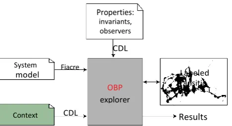
Context-aware verification focuses on modelling of the environment as a set of contexts. Furthermore, for our model-checking approach, the SUS is modelled using the formal language Fiacre [15], which enables the specification of interacting behaviours and constraints through automata. The surrounding environment and requirements are specified using the CDL formalism, and verified by the model-checker OBP2 (Observer Based Prover):
.
The methodology proposed for the context-aware model-checking verification, is a kind of co-design methodology along three axes: a) the model of the SUS is elaborated using UML state diagrams expressed with a textual representation called tUML, transformed automatically into Fiacre models; b) the contexts are formalized with CDL; c) we need to formalize properties to be checked on the elaborated model.
Our work focuses on context description based on informal use cases. The use cases that we seek are those with a textual format. The specification of these use cases should be controlled through a set of writing rules and instantiated from a use case meta-model. This control is performed so as to reduce ambiguity and facilitate the generation of behavioural models (CDL) from such instances. This allows precisely synthesizing the structure of our context description formalism as activity diagrams (with both actors and system partitions) by a set of transformation rules using an interaction meta-model. Because contexts focus on the system boundaries, the system partition is replaced by gates connected to the actors' interactions. IODs express use cases coordination at the higher level. The whole set of interaction diagrams constitute the high-level specification point of view from which CDL contexts are generated. The generated CDL models are used directly by OBP tools to assess the context part of the model submitted for verification. The double arrows between meta-models
1
Language and Tools set website: http://www.obpcdl.org
transformations mean the ability to establish traceability links to ease the debugging process. See Figure 3.
Figure 3. Methodology for a context-aware verification process
It’s out of the scope of this paper to illustrate the whole verification process; rather we focus on application of our proposal of transformation rules to generate contexts (area squared with red in Figure 3).
5. From Use cases to Activities: elaborate
context
In this section we give our meta-models, resulting diagrams after applying transformation rules and generated IODs.
5.1.
Meta
-models
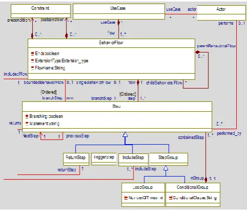
Establishing good meta-models is a challenging task because we need to have meta-models conforming to the UML meta-model in order to ease the exchange of models produced by various UML tools. But we need also to keep the meta-models concise and sound. Hence, our use case and activity diagram meta-models borrow as much as possible constructs and hierarchy from those in UML 2.4.1[14]. However, we have simplified and tuned them for our own purposes. Because use case structure is semi-formal, for model-checking verification purposes, we need to precise the use case structure. See Figure 4.
Properties: invariants, observers
CDL
System
model Fiacre
OBP
explorer
Labeled transitio
n system
Context CDL Results
5
Figure 4. Use case Meta-model
A use case is associated to one or many scenarios, called
BehaviourFlow, some of them are main scenarios. A
BehaviourFlow is made of an ordered sequence of Steps:
SingleStep or StepGroup. A StepGroup contains an ordered sequence of Step, including other StepGroups recursively. A
SingleStep may be specialized in: TriggerStep (the condition triggering a BehaviourFlow), IncludeStep (the step contains another BehaviourFlow), ReturnStep (a return to another Step), FinalStep (the use case ends). A StepGroup is a
LoopGroup or a ConditionalGroup. A BehaviourFlow can have extension(s) (alternatives that describe different steps than those in a success scenario) and it applies recursively.
A child BehaviourFlow refers to a parent BehaviourFlow
and states the branching point where the extension condition (a TriggerStep) should be checked: a single branching point or a bounded interval; in the latter case, the condition can occur at any steps within the bounds and triggers the child BehaviourFlow.
The second meta-model that we use is that of activity diagram. In this meta-model, Activity is a generalization of
ActivityNodes and ActivityEdges for linking between them.
ActivityNode is either a simple action, a ControlNode (decision, fusion, etc) or some specialization of groups of
StructuredActivity in looped and conditional forms. An
ActivitygGroup generalizes also the partition notionthat gathers activities for each actor. Activity meta-model is given as follows:
Figure 5. Activity Meta-model
5.2. A running model-checking example
We use a famous concurrency problem to illustrate a typical model-checking process, the context-aware approach and to introduce our proposal later. It’s about Lamport’s problem of two neighbours Alice and Bob that share a yard in an exclusive manner [15]. This problem is presented within the following algorithm:
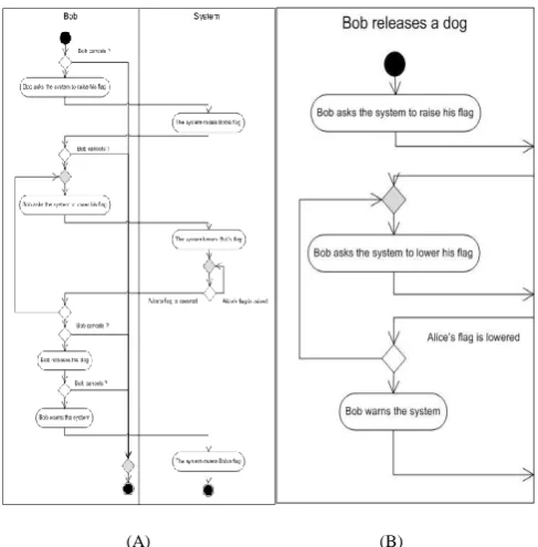
According to our context-aware verification approach, we need the followings artefacts: i) the system is translated into specification model to describe the behaviours of Alice and
Bob, in the form of automata given in left side (A) in Figure 6. The expression evRain [catIn-Yard = true /
AliceCatGoesHome] means that when the event evRain
occurs and if the condition catInYard = true is satisfied then the action AliceCatGoesHome is performed. ii) Contexts are given through use cases “Alice’s cat comes home” and “Bob releases a dog” given in middle (B) and right sides (C),
respectively. iii) A property to be checked, formalized using CDL, for instance the mutual exclusion property may be represented with not (catInYard and dogInYard).
EAI Endorsed Transactions on Context-awareSystemsandApplications
Finally the model-checker is run to check the validity of the property on OBP. For example, the model-checker would not find any state where the mutual exclusion property is falsified.
5.3. Transformation rules
Transformation of textual use cases to activity diagrams is realized in three phases as follows:
1) Basics creation: a use case generates an activity diagram, each actor generates a partition and a partition for the system is added; rules BCR1, BCR2, BCR3,
BCR4 and BCR5 are applicable on the whole use case. 2) Activity node creation: control nodes, structured nodes
and action nodes; ANR1, ANR 2, ANR 3 and ANR4 with their sub rules applicable after Basics creation.
3) Activity edge creation: connecting activity nodes with control flows, rules AER1, AER2, AER3 and AER4. A summary of our transformation rules in the form of an algorithm is given as appendix at the end of this paper. However, we show now how there are applied on the use case “Alice’s cat comes home” given above. More details and full rules are found in [16]
Activity nodes
Rules BCR1 and BCR 2 are respectively applied to generate an activity diagram, an Alice and system partition and also an InteractionUse for this activity diagram that will be contained in the IOD related to the actor Alice. With rule BCR 3 the ain scenario and the three extensions generate (including together 8 steps) four ActivityGroups. For generating the rest of activity nodes, we proceed as follows:
Apply rule BCR 4: - Generate an InitialNode into the
ActivityGroup of the main flow.
Apply rule BCR5: - Generates 3 ActivityFinalNode for
each flow that ends within their corresponding
ActivityGroup.
Apply rule ANR2.a: - Generates a FusionControlNode
added at the ActivityGroup and pending to the second
ActivityNode of this ActivityGroup for the
BoundedBehaviorFlow 1-3a. Cancelling (shortcut for avoiding the repetition of Cancelling at each step of the main scenario).
Apply rule ANR4: - unfold the BoundedBehaviorFlow in 2
occurrences of Cancelling with 2 DecisionControlNodes
generated and linked to this FusionControlNode, the former after the step 1 (before the step 2) and the latter after the step 2 (before the step 3).
Apply rule ANR2.b: Unfolding the Cancelling
BoundedBehaviourFlow leads to 2 BehaviourFlows (Phone call and Cancelling) branching after step 1 and indeed to have 2 BehaviourFlows (Silly cat and Cancelling) branching after step 2.
Apply rule ANR3.a: - Generate 4 DecisionControlNodes
from the 4 triggers (steps that begin the BehaviourFlow) with the first DecisionControlNode located in Alice IOD, these 4 DecisionControlNodes are pending to the first
ActivityNode of each corresponding ActivityGroup; and the remaining 4 steps generate 4 ActionNodes (rule ANR3). Activity Edge
ActivityEdges are generated for linking ActivityNodes. Let us see what will be generated from our use case ”Alice’s
cat comes home”.
Apply rule AER1: - Generates an ActivityEdge from the
InitialNode to the first DecisionNode before the ActionNode Alice opens the door to her cat.
Apply Rule AER2: - Generates 3 ActivityEdges to the 3
ActivityFinalNodes from the last ActivityNode of each
ActivityGroup associated with each BehaviourFlow that ends. Because the ActivityGroup associated with the flow
Silly cat contains only the ActivityFinalNode (the flow contains a single step), this ActivityFinalNode has been already linked as a target from the ActivityEdge generated from the processing of the TriggerStep during the activity node generation, hence this ActivityEdge is not generated.
Figure 5. Activity Meta-model
Figure 6. Automata of Alice and Bob behaviours (A) “Alice’s cat comes home” use case (B)
7
Apply rule AER3: - Generates 2 ActivityEdges for the
ActionNode Alice opens the door to her cat and 1
ActivityEdge for the ActionNode Alice asks the system to lower her flag. These ActivityEdges link together the
DecisionControlNodes after an ActionNode and the last
DecisionNode either to a FusionControlNode (case of the former ActionNode) or to the ActionNode (latter case).
Apply rule AER4:- Generates 2 ActivityEdges sourcing
from the 2 ActionNodes that are non-ending steps and targeting the first ActivityNode of each following
ActionNode (a DecisionNode in both cases).
Figure 7 shows the generated activity diagram as follow:
Figure 7. The generated activity diagram for “Alice’s Cat goes home” use case
5.4. Specification of the system boundaries
Our aim now is to transform the resulting activity diagrams to our first type of IODs, focusing only on the actor’s partition and its interactions with the system. To do this, we need to use boundaries to establish the interface (focusing on exchanged messages) between the system and its environment. Our IODs are established as follows: first, we recommend writing actions with simple sentences having a subject, a verb, and eventually an object. Actions without the system as a subject or an object (such as Alice opens the door to her cat) are out of the scope and will be discarded. Compound actions (such as Alice releases her cat and warns the system) have to be split in simple actions (such as Alice releases her cat - out of the scope - and Alice warns the system) - within the scope). When the simple sentence rule is applied, it is easy to process ActionNodes and recognize if the system is a subject or an object and eventually discard the ActionNode from the system scope. The same rule applies to DecisionControlNodes: if the condition includes
any reference to the system, the DecisionControlNode will be kept, else discarded. Any incoming or outgoing
ActivityEdges to a discarded ActivityNode (Action or
Decision) will be discarded too, and the pending
ActivityEdge reconnected to the following ActivityNode (that might be discarded later, forcing the ActivityEdge to be reconnected).
At the end, a set of nodes are discarded. Moreover, there are ActivityEdges crossing the boundary and because the system partition is not included, such ActivityEdge will be cut and replaced by a pair of related gates, one is the actor’s model and another is the system model. Thus, an IOD is established for each actor (Actor IOD). See Figure 8:
Figure 8. IOD and system boundaries
The activity diagram (left side (A)) and its IOD (right side (B)) generated from the use case “Bob releases a dog”
are given in Figure 9:
(A) (B)
Figure 9. IOD corresponding to the use case “Bob
releases a dog” and System Boundaries SUS Actor IOD
Boundaries
MessageIn
MessageOut
Gates
EAI Endorsed Transactions on Context-awareSystemsandApplications 11 2015 - 022016|Volume 3 |Issue 7|e2
After this step, the specification engineer has to identify and gather all gates pair in the Interface Requirements Specification Document. We expect to have an interface specification including types, messages and events. For our purposes, the interface specification has to be abstracted as a list of UML Messages whose semantic is simply the trace <sendEvent, receiveEvent>.
5.5. Orchestration of activity diagrams with
IODs
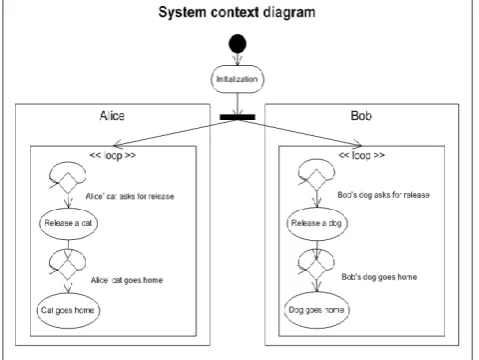
The last step towards elaborating contexts is to organize all interactions in higher-level diagrams. Our second type of IODs fits for this purpose. Such IODs focus on the overview of the flow of control where the nodes are (inline)
Interactions or InteractionUses. The specification engineer is free to orchestrate interactions from different system viewpoints or from his engineering needs. He should be aware of the structure of the CDL language. For instance, uses concurrency at the higher level, corresponding to CDL Level-1 and fully describe scenarios by sequence diagrams, corresponding to CDL Level-3.
Figure 10. Example of an IOD used for orchestrating a set of use cases
With these recommendations, there will be no difficulties to generate CDL diagrams from these IODs.
6. Related work and comparison
Many works exist in applying compositional verification techniques as in [17, 18, 19, 20]. These works deal with model checking/analyzing individual components (rather than whole systems) by specifying, considering, or even automatically determining the interactions that a component has with its environment. Our approach is different from such compositional or modular analysis. Context aware verification is not about verifying component by component, with the ”traditional” techniques where contexts are often
included in the system model. Rather, we explicit contexts separately from the model. Further, such approaches use temporal logic-based languages for specification (LTL [21] or CTL [22] for example) since we use the specific domain language CDL based on context description.
Using use cases to elaborate contexts for context-aware model-checking approach has been intended in some similar works. Such approach has a limited audience because use cases often lack of precision. However we can compare our work with other research works that process use cases for different purposes as long as the purpose requires a precise semantics.
The work presented in [23] describes an approach to translate use case-based functional requirements to activity charts. The source models are use cases diagrams with support of high-level relationships like inclusion and generalization; our approach focuses on the detailed relationships between BehaviourFlows.
In [24], authors proposed a model-based approach to generate activity diagrams for modelling scenarios. A functional requirement meta-model was proposed to represent use cases scenarios with possible exceptions. The goal of this approach is not stated clearly and although our work shares some transformation rules with it, the generality of their approach limits its employability. In our case, the generated activity diagrams are employed in further steps within the verification methodology and contribute to the goal of generating contexts.
In [25], Authors used a restricted use cases modelling approach with rules and a template to produce use cases that are transformed automatically in activity diagrams. The authors claim that quality activity diagrams can be generated and that their approach outperforms existing commercial tools. This work is closest to ours, we share some techniques with it but such approach is also too general. Our approach differs in the sense that we go beyond generating activities from use cases scenario and that we contribute to other phases of the verification process such as the interface specification and decreasing the state space with contexts. Another similar work is proposed in [26] that presents an algorithm that transforms use cases into activity diagrams to facilitate the construction of formal requirements specification models. The source use case models are presented in the form of textual use case with a defined template and structure. However, such use cases are those that model the exceptional behaviour (extensions) introduced using special stereotypes which we handle using the notions of Parent and child BehaviouralFlows in our approach. Transformation algorithm and rules are similar and it still manual as well as in our case.
9 language and does not require any rewriting of the statements or constraint on the input format, whereas our work is based on semi structured format in the form of textual use cases and rewriting rules. Furthermore, its objective fits to improve software requirements analysis and development in general, and generating behavioural diagrams are not addressed to elaborate contexts in the favour of formal verification with a context-aware approach such as in our work. Using IODs for orchestrating high-level interactions is also a surplus in our favour.
In order to help specification engineers, authors in [28] proposed an approach that reuses models of existing web applications for specification of requirements of new web application. It takes brief description of the requirements in terms of use case diagram, and generates the drafts of the detailed description in terms of activity diagrams using an ontology repository and annotation algorithm. A use case similarity metric is used for retrieving, from the model repository, the use cases which are similar to the new. Compared with our work, this approach is semi automated and another adaptation algorithm is used to adapt the annotated activity diagram for the new use cases. It fits in the Web engineering framework where the semantic web data model is the underlying representation format.
Appendix A. Transformation rules
Table1. Algorithmic presentation of transformation rules
Input: textual Use case
For all (UseCase)
BCR 1: a use case generates an activity diagram
BCR 2: an Actor generates a Partition
BCR 3 :BehaviourFlowgenerates anActivityGroup
BCR 4: a main BehaviourFlowgeneratesanAcitivityInitialNode
For all (BehaviourFlow )
BCR 5: if (ENDS = true ) then ( //* do not terminate with a
ReturnStep)
- Generate an ActivityFinalNode such as each ActivityFinalNode is added to its corresponding Activity- Group.
ANR1 : if (BehaviourFlow. ExtenstionType = singleBehaviourFlow)
then
ANR1.a : if (1 extension)
- Generate a DecisionControlNodeand an ActivityEdge has as source its corresponding DecisionControlNode and as a pending target the first ActivityGroup generated from the
c h i l d B e h a v i o r F l o w. else
ANR1.b: if (N extensions)
- Generate N DecisionControlNode (f o r e a c h
C h i l d B e h a v i o u r F l o w ) in cascade and N ActivityEdge
h a v i n g a s source their corresponding DecisionControlNode and as pending target the first ActivityGroup generated from the corresponding C h i l d BehaviorFlow.
ANR2: if(BehaviourFlow. ExtenstionType =
boundedBehaviourFlow) then
if (1 extension)then
ANR2.a: - Generate a FusionControlNode for the
ParentBehaviorFlow (from a DepartureStep m to an
ArrivalStep n) at the first place of the ActivityGroup
generated from the c h i l d BehaviorFlow and an
ActivityEdge having as source this FusionControlNode
and as a pending target the second ActivityNode of this
ActivityGroup.
ANR2.b: - Generatea DecisionControlNode for each step in
the interval [m, n] of the ParentBehaviourFlow, n-m+1
DecisionControlNode are generated in total.
- G e n e r a t e n-m+1ActivityEdge having as source its corresponding DecisionControlNode and as a pending target the first FusionControlNode of the
ActivityGroup generated from the c h i l d BehaviorFlow).
Else
if (N extension)then
ANR2.c: - Generate N FusionControlNode for the
ParentBehaviorFlow (from a DepartureStep m to an
ArrivalStep n) at the first place of the ActivityGroup
generated from the c h i l d BehaviorFlow and an
ActivityEdge having as source this FusionControlNode
and as a pending target the second ActivityNode of this
ActivityGroup.
ANR2.d: - GenerateN DecisionControlNode for each
step in the interval [m, n] of the ParentBehaviourFlow, N (n-m+1) DecisionControlNode are generated in total.
- G e n e r a t e N(n-m+1)ActivityEdge, hence each having as source its corresponding
DecisionControlNode and as a pending target the first
FusionControlNode of the ActivityGroup generated from the c h i l d BehaviorFlow).
For all (Step)
ANR3: A Step in a BehaviorFlow generates, generally, an
ActionNode (in the ActivityGroup generated from the
BehaviorFlow) with the following exceptions:
If (Step = TriggerStep) then
ANR3.a: Generates a DecisionControlNode associated to the
ActivityGroup generated from the BehaviorFlow) and an ActivityEdge
having as a source this DecisionControlNode and as a pending target the first ActivityNode of the ActivityGroup generated from the
BehaviorFlow.
Else if (Step = ReturnStep) then
ANR3.b: The first ReturnStep to a given Step generates a
FusionControlNode and an ActivityEdge having as source this
FusionControlNode and as target the ActivityNode generated from the given Step; another ReturnStep to the same Step does not generate anything else.
Else if (Step= IncludeStep) then
ANR3.c: The first IncludeStep to a given BehaviorFlow generate a
FusionControlNode and an ActivityEdge having as source this
FusionControlNode and as a target the first ActivityNode from the Activity Diagram; another IncludeStep to the same BehaviorFlow
does not generate anything else. Else if (Step= StepGroup) then
ANR3.d: A StepGroup (either a LoopGroup or a ConditionalGroup) generates a StructuredActivityNode (either a LoopNode or a
ConditionalNode), then rule ANR3 is applied recursively to the
StepGroup.
ANR4: Resolve all pending targets of any ActivityEdge thanks to
the completion of the ActivityGroup. For all (main BehaviourFlow)
AER1: Generate an ActivityEdge having as source the InitialNode and as target the first ActionNode from the ActivityGroup generated from such BehaviourFlow.
Forall (BehaviourFlow)
if( ENDS = true and non-empty ActivityGroup) then
AER2: Generate an ActivityEdge having as target its
ActivityFinalNode and as source the last ActivityNode of the
ActivityGroup generated from such BehaviourFlow.
For all (Step)
if (Branching = true) then (for one or N extensions)
AER3: generate one orN ActivityEdge for linking together the
generated DecisionControlNode byANR1 (ANR1.a and ANR1.b). The N-th ActivityEdge links the last DecisionControlNode to the
FusionControlNode associated with the Step in questionif this
FusionControlNode exists else to the ActivityNode generated from such Step (either an ActionNode or a
StructuredActivityNode)
AER4: For each ActionNode generated from a non-ending Step
(being not followed by a ReturnStep or End), generates an
ActivityEdge having as source the ActionNode and as target, either the next ActionNode if no DecisionNode or FusionControlNode
are associated to, or the first of these ControlNodes.
Output: Activity diagram
7. Conclusion and future work
This paper has presented an overview of a part of the method aiming to facilitate system verification from informal requirements. Thanks to elaboration and
EAI
European Alliance for Innovationtransformation activities, the semantic gap between informal and formal requirements is reduced and engineers helped towards formal verification.
As [26], our approach is still manual. However, we aim to automate the transformation process for a validation purpose on an industrial case study to check the completeness and correctness of our transformation rules. A framework for automation like Ecore for meta-models implementation and Java for rules transformation are among proposals. However, we are looking for a solution that might be easily customized to the tools set used by the users: XML Metadata Interchange (XMI) enables interchange of meta-data between UML-based modelling tools but there might be slightly differences between the tools meta-models.
References
[1] Pelanek, R. (2009) " Fighting state space explosion: Review and evaluation". In Formal Methods for Industrial Critical Systems, volume 5596, pages 37{52. Springer Berlin Heidelberg, 2009.
[2] Alur, R., Brayton, R., Henzinger, T., Qadeer, S. and Rajamani, S. (1997) " Partial-order reduction in symbolic state space exploration". In Computer Aided Veri_cation, volume 1254, pages 340_351. Springer Verlag, LNCS, 1997. [3] Valmari, A. (1991) "Stubborn sets for reduced state space
generation". In Proceedings of the 10th International Conference on Applications and Theory of Petri Nets, pages 491_515, London, UK, 1991. Springer-Verlag.
[4] Park,. S and Kwon, G. (2006). "Avoidance of state explosion using dependency analysis in model-checking control flow model". In Proceedings of the 5th International Conference on Computational Science and Its Applications (ICCSA '06), volume 3984, pages 905_911. Springer-Verlag, LNCS, 2006 [5] Bosnacki, D. and Holzmann, G. (2005) " Improving spin's
partial-order reduction for breadth-First search". In SPIN2005, volume 3639, pages 91_105, 2005.
[6] Dhaussy P, Boniol, F. and Roger, J. (2011a). "Reducing State Explosion with Context Modeling for Model-Checking. In 13th IEEE International High Assurance Systems Engineering Symposium (Hase’11), Boca Raton, USA, 2011. 5, 37, 38, 39, 40, 44.
[7] Dhaussy, P. Boniol, F. Roger, J. and Leroux, L. (2012a). Improving model-checking with context modeling. Advances in Software Engineering, ID 547157:13 pages, 2012. [8] Dhaussy, P. and Roger, J. "CDL (Context Description
Language) : Syntax and Semantics". Rapport technique, ENSTA- Bretagne, 2011. 37
[9] Dhaussy, P., Roger, J., Leroux, L. and Boniol, F. "Context Aware Model Exploration with OBP tool to Improve Model-Checking". ERTS'12, February 1-3, 2012.
[10] Chaelynne M. Wolak, (2001) "Gathering Requirements: The Use Case Approach". School of Computer and Information Sciences , Nova Southeastern University ,June 2001
[11] Whittle, J. (2006) "Specifying precise use cases with use case charts". In Proceedings of the 2005 International Conference on Satellite Events at the MoDELS, pages 290{301. Springer-Verlag, 2006.
[12] Dhaussy, P., Pillain, P., Creff, S., Raji ,A., Le Traon, Y. and Baudry, B.(2009) "Evaluating context descriptions and property definition patterns for software formal validation". In 12th IEEE/ACM conference on Model Driven Engineering
Languages and Systems (Models'09), volume 5795, pages 438_452. Springer-Verlag, LNCS, 2009.
[13] OMG UML. “OMG unified modeling languageTM , infrastructure". Technical report, Object Management Group, (http://www.omg.org/spec/UML/)
[14]Berthomieu, J., Bodeveix, JP., Farail, P., Filali, M., Garavel, H., Gaufillet, P., Lang, F. and .Vernadat, F. (2008) " Fiacre: an intermediate language for model verification in the topcased environment". In ERTS 2008. 2008.
[15] Lamport, L. (1983) "invited address solved problems, unsolved problems and non-problems in concurrency". In Proceedings of the Third Annual ACM Symposium on Principles of Distributed Computing, pages 1{11. ACM, 1984.
[16] Benabbou A. (2015) "Formalisation des interactions et des exigences pour la génération des modèles cdl "- partie 1 : Contextes. Technical Report 2015-03-01, ENSTA Bretagne. [17] E. M. Clarke, D. E. Long, and K. L.
Mcmillan, Compositional Model Checking, MIT Press, 1999. [18] L. De Alfaro and T. A. Henzinger, “Interface automata,”
in Proceedings of the 8th Eiropean Engineering Conference and 9th ACM SIGSOFT Symposium on the Foundations of Software Engineering (FSE '01), pp. 109–120, ACM Press, September 2001.
[19] Cormac, F. and Shaz Q.(2003)” Thread-modular model checking”. In SPIN’03, 2003.
[20] Oksana, T. and Matthew, D.(2003)” Automated environment generation for software model checking”. In Proceedings of the 18th International Conference on Automated Software Engineering, pages 116–129, 2003.
[21] Pnueli, A. (1977) "The temporal logic of programs". In SFCS '77: Proceedings of the 18th Annual Symposium on Foundations of Computer Science, pages 46_57, Washington, DC, USA, 1977. IEEE Computer Society.
[22] Clarke, E., Emerson, E. and Sistla, A. (1986) "Automatic verification of finite-state concurrent systems using temporal logic specifications". ACM Trans. Program. Lang. Syst., 8(2):244_263, 1986.
[23] Almendros, J. and Iribarne, L. (2005) "Describing use cases with activity charts". In Metainformatics, volume 3511, pages 141–159. Springer Berlin Heidel- berg, 2005.
[24] Gutierrez, C., Nebut, M., Escalona, M., Mejas, I. and Ramos, M. (2008) "Visualization of use cases through automatically generated activity diagrams". In Model Driven Engineering Languages and Systems, pages 83{96. Springer Berlin Heidelberg, 2008.
[25] Tao, Y., Lionel, C., Briand, and Yvan, L. (2010) "An automated approach to trans-form use cases into activity diagrams". In Modeling Foundations and Applications, pages 337{353. Springer, 2010.
[26] Mustafiz, S., Kienzle, J., and Vangheluwe, H.(2009) "Model transformation of dependability-focused requirements models". In ICSE Workshop on Modeling in Software Engineering, MISE '09, pages 50{55. 2009.
[27] Sharma, R., Gulia, S., Biswas, K. (1977)” Automated Generation of Activity and Sequence Diagrams from Natural Language Requirements”. ENASE 2014: 69-77