R E S E A R C H A R T I C L E
Open Access
The accuracy and stability of the maxillary
position after orthognathic surgery using a
novel computer-aided surgical simulation
system
Ju-Won Kim
1,4,5†, Jong-Cheol Kim
1,2†, Chun-Gi Jeong
2, Kyeong-Jun Cheon
1,4, Seoung-Won Cho
1,4,
In-Young Park
3,4,5and Byoung-Eun Yang
1,4,5*Abstract
Background:Many reports have been published on orthognathic surgery (OGS) using computer-aided surgical simulation (CASS). The purpose of this study was to evaluate the accuracy of the maxillary repositioning and the stability of the maxilla in patients who underwent OGS using a newly developed CASS program, a customized osteotomy guide, and a customized miniplate.
Methods:Thirteen patients who underwent OGS from 2015 to 2017 were included. All patients underwent a
bimaxillary operation. First, a skull-dentition hybrid 3D image was rendered by merging the cone beam computed tomography (CBCT) images with the dentition scan file. After virtual surgery (VS) using the FaceGide® program, patient-customized osteotomy guides and miniplates were then fabricated and used in the actual operation. To compare the VS with the actual surgery and postoperative skeletal changes, each reference point marked on the image was compared before the operation (T0) and three days (T1), four
months (T2), and a year (T3) after the operation, and with the VS (Tv). The differences between ΔTv (Tv-T0)
and ΔT1 (T1-T0) were statistically compared using tooth-based reference points. The superimposed images of
Tv and T1 were also investigated at eight bone-based reference points. The differences between the
reference points of the bone surface were examined to evaluate the stability of the miniplate on the maxilla over time.
Results: None of the patients experienced complications. There were no significant differences between the
reference points based on the cusp tip between ΔTv and ΔT1 (p> 0.01). Additionally, there were no
significant differences between the Tv and T1 values of the bone surface (p > 0.01). The mean difference in the bone surface between Tv and T1 was 1.01 ± 0.3 mm. Regarding the stability of the miniplate, there were
no significant differences between the groups. The difference in the bone surface between T1 and T3 was −
0.37 ± 0.29 mm.
(Continued on next page)
* Correspondence:[email protected];[email protected]
†Ju-Won Kim and Jong-Cheol Kim contributed equally to this work.
1Division of Oral and Maxillofacial Surgery, Hallym University Sacred Heart
Hospital, 11, Gwanpyeong-ro 170beon-gil, Dongan-gu, Anyang-si, Gyeonggi-do, 14066 Anyang, Republic of Korea
4Graduate School of Clinical Dentistry, Hallym University, Chuncheon,
Republic of Korea
Full list of author information is available at the end of the article
Skeletal malocclusion affects oral health and is highly as-sociated with dental trauma and masticatory difficulties as secondary effects of parafunction and teeth crowding
[1]. Orthognathic surgery (OGS) is used to resolve
im-balances involved in the craniofacial structure and skel-etal malocclusion, thereby improving the oral and facial function and aesthetics of the patient. The efforts of both orthodontists and surgeons can dramatically im-prove the quality of life of patients experiencing
func-tional and aesthetic discomfort. However, jaw
misplacement by a surgeon during OGS is difficult for an orthodontist to revise after the operation. During traditional bimaxillary OGS, the maxilla is first moved, and the mandible is relocated relative to the maxilla. Therefore, it is most important to move the maxilla to a planned position during OGS. Efforts to achieve such
outcomes include freehand relocation [2] and the use of
an internal reference point, which are currently applied by several surgeons. However, external reference points are the most accurate method to use during LeFort I
osteotomy [3]. In recent years, the progress in OGS has
mainly resulted from the use of a virtual surgery plan
(VSP) to accurately reposition the bone segments [4].
There are problems associated with conventional OGS and several reasons why VSPs are favored. An analysis of dentofacial deformity is based on the information ob-tained through several preoperative examinations. Once the analysis is completed, subsequent surgical planning is initiated using a visual treatment objective (VTO), which determines where each component should be po-sitioned in relation to the fixed reference structure (skull base) and another. When the VTO involves the move-ment of only a single jaw, either the maxilla or mandible, a simple hinge articulator is sufficient for mock surgery. However, when the VTO involves the movement of both jaws, a semi-adjustable articulator is used as these artic-ulators can better reproduce the centric relation (CR) and centric occlusion within an acceptable anatomical average. The most difficult aspect in performing model surgery is in the repositioning of the maxillary cast
dur-ing bimaxillary surgery [5]. After the mock surgery is
performed according to the surgical plan, two surgical occlusal splints (an intermediate splint (IMS) and a final splint) are made for bimaxillary surgery. Occlusal splints
relationships and eliminate unreliable intraoperative
guesswork [6]. As the first step in simulating a
bimaxil-lary surgery, a face-bow transfer procedure is required to transfer the maxilla to a semi-adjustable articulator.
However, it is impossible to transfer the patient’s
maxil-lary dentition to the articulator and accurately reproduce
the patient’s anatomy [7–10]. In addition, it is difficult to
achieve complete three-dimensional (3D) movement in a model surgery in cases of patients with severe facial anomalies, even though the face-bow is used to correctly
reproduce the patient’s actual maxillary position in the
articulator. During the model surgery, the upper arm of the semi-adjustable articular is used as a reference for moving the maxillary cast. However, the most common technique for repositioning the maxilla in the operating room is the use of an external reference point with the help of the IMS. Therefore, the sub-stantive reference for repositioning the maxilla is the mandible. In most cases, OGS requiring maxillary movement is performed under general anesthesia. Some researchers have reported that the position of the mandible deviates from its normal position under
general anesthesia [11, 12]. Even if a face-bow
trans-fer is performed well enough to accurately reflect the anatomy of the patient, the model surgery is per-formed well, and the IMS is made perfectly, errors may occur when the surgeon uses the mandible as a reference and repositions the maxilla using only the IMS. Therefore, considerable time is required to de-termine the desired position of the maxilla when con-ventional bimaxillary surgery is planned. Recently, computer-aided surgical simulation (CASS) and device manufacturing using computer-aided design (CAD) and computer-aided manufacturing (CAM)
technolo-gies have attracted attention for precise OGS [13, 14].
Methods
Subjects
Thirteen patients were selected from a list of medical re-cords. The sample consisted of seven females and six
males with a mean age of 22.9 ± 3.3 years (range, 18–29).
The patients were selected according to the following in-clusion criteria: (1) patients who underwent surgery be-tween February 2015 and August 2017; (2) those who completed presurgical orthodontic treatment; and (3) pa-tients who underwent bimaxillary surgery to treat skeletal malocclusion. The exclusion criteria were as follows: (1) patients with cleft palate or craniofacial anomalies; (2) pa-tients who had not undergone surgery with FaceGide®; and (3) patients who were unwilling to participate in this study. All medical practices conformed to the Declaration of Helsinki as a medical protocol. The study protocol was
approved by the hospital’s Institutional Review Board (IRB
No. 2018–06-016). All patient data were anonymized and
de-identified prior to the analysis. Detailed patient
charac-teristics are presented in Table1.
Preoperative procedures and virtual OGS
Our protocol for OGS with the FaceGide® system was as
follows (Fig.1). Clinical photographs of the patient were
taken after a clinical examination. CBCT (Alphard 3030, Asahi, Inc., Kyoto, Japan) was performed two weeks before the surgery to obtain a 3D image of the patient. All images were obtained with the Frankfort plane parallel to the horizontal plane, a field of view of 200 × 200 mm, a voxel size of 0.39 mm and exposure conditions of 80 kVp, 5 mA, and 17 s. The patients were scanned wearing a CR wax bite to ensure that their condyles were scanned in the CR position, that is, with the condyle resting in the glenoid fossa. With CBCT, a
patient’s dental structure cannot be obtained accurately
due to bracketing, blurring, and enlargement of the image. Almost all orthodontic patients wear fixed metal orthodontic appliances or have metallic brackets, which produce striped artifacts that distort the view of the dentition and occlusions during scanning. Therefore, a conventional impression was taken, and a pair of stone casts was fabricated for each patient. The surface image of the casts was then digitized into surface tessellation language (STL) format using a desktop model scanner (Freedom HD; Dof, Inc., Seoul, Korea). The CBCT im-ages were transformed into DICOM format, and three-dimensionally reconstructed. Then, the CBCT re-construction and the dental cast scan files were sent to the digital center. Subsequently, the DICOM and STL files were imported into a planning software program.
The patient’s CBCT scan and the scanned image of the
patient’s dental cast were registered. Semiautomatic
merging started with registration of the image of the teeth obtained from the dental cast to the CBCT image of the teeth, which is relatively accurate. The images were merged process via manual registration by select-ing three anatomical landmarks from the dentition. The contour of the dental cast image placed on the CBCT image was examined, and fine adjustments were made if necessary. The next step was reorientation of the skull image to reconcile the views of the surgeon, the orthodontist, and the digital technician. In this way, the final virtual hybrid skull-dentition 3D image (virtual face) was obtained. The reorientation image was sent to the surgeon, and telecommunication with the digital technician took place via the computer screen. The position of the osteotomy, the movement of the bone segment, the position of the customized plate, and the
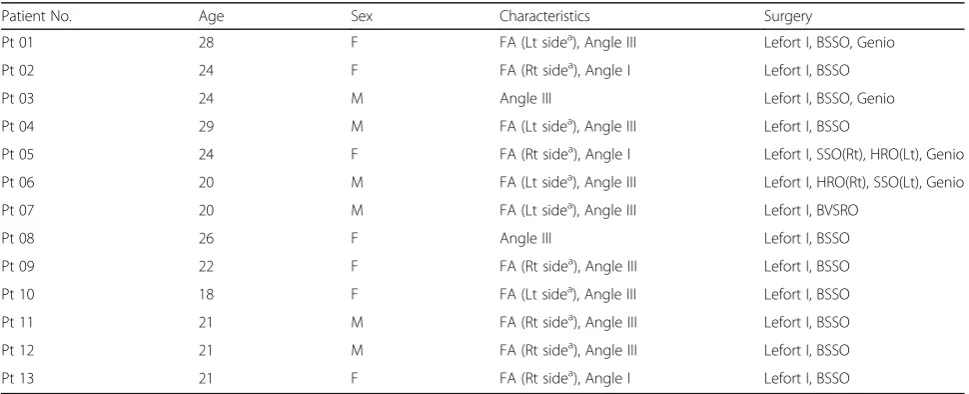
Table 1Patient characteristics and surgery descriptions
Patient No. Age Sex Characteristics Surgery
Pt 01 28 F FA (Lt sidea), Angle III Lefort I, BSSO, Genio
Pt 02 24 F FA (Rt sidea), Angle I Lefort I, BSSO
Pt 03 24 M Angle III Lefort I, BSSO, Genio
Pt 04 29 M FA (Lt sidea), Angle III Lefort I, BSSO
Pt 05 24 F FA (Rt sidea), Angle I Lefort I, SSO(Rt), HRO(Lt), Genio
Pt 06 20 M FA (Lt sidea), Angle III Lefort I, HRO(Rt), SSO(Lt), Genio
Pt 07 20 M FA (Lt sidea), Angle III Lefort I, BVSRO
Pt 08 26 F Angle III Lefort I, BSSO
Pt 09 22 F FA (Rt sidea), Angle III Lefort I, BSSO
Pt 10 18 F FA (Lt sidea), Angle III Lefort I, BSSO
Pt 11 21 M FA (Rt sidea), Angle III Lefort I, BSSO
Pt 12 21 M FA (Rt sidea), Angle III Lefort I, BSSO
Pt 13 21 F FA (Rt sidea), Angle I Lefort I, BSSO
FAFacial asymmetry,AngleAngle malocclusion classification,Lefort I, Lefort I osteotomy,BSSOBilateral sagittal split ramus osteotomy,HROHorizontal ramus
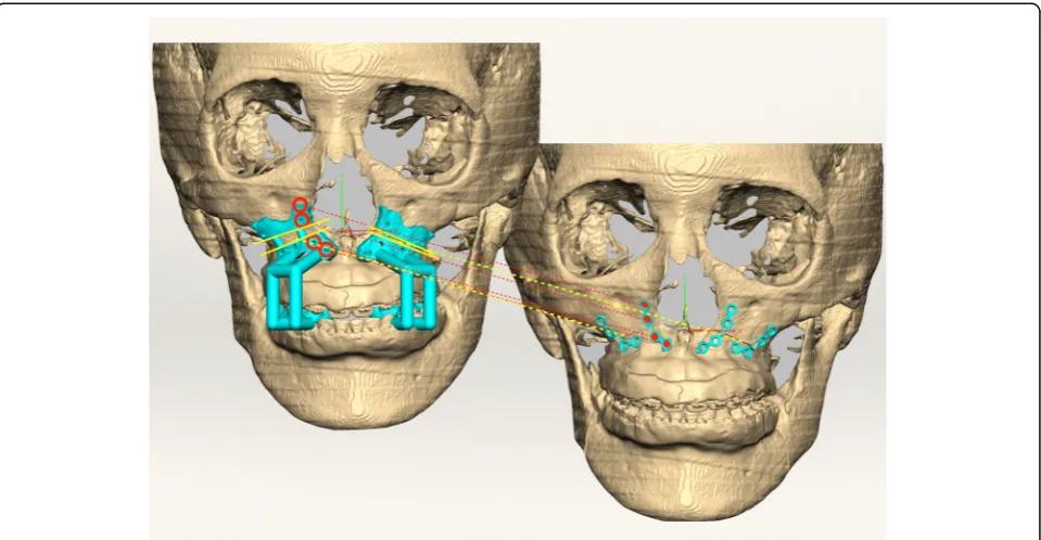
final occlusion were determined. After the final confir-mations were made, virtual materials (such as the patient-customized osteotomy guides (PCGs), PCMs,
and splints) were designed (Fig. 2). After the surgeon
checked them, their images were exported as STL files.
Then, the actual materials were produced by a rapid prototyping machine (S30 3D printer, Rapid Shape GmbH, Heimsheim, Germany) and a computer numer-ical control (CNC) machine (ARDEN, TPS Korea Ltd., Gwangju, Republic of Korea).
Fig. 1Workflow of orthognathic surgery using the FaceGide® system
Actual OGS
All physical components and reports regarding the VS showing the PCGs (including drilling holes) and PCMs were sent to the surgeon before the OGS. These mate-rials were then delivered to the operating room for
sterilization (Fig. 3a, b). The maxilla was repositioned
and fixed with four L-shaped PCMs and monocortical self-drilling screws. The customized maxillary miniplates have holes corresponding to the drilling holes in the PCGs. As a result, bone holes are precisely formed using PCGs, and prefabricated miniplates are fitted to these
holes (Fig. 3c, d). The PCM was positioned by merely
inserting a self-drilling screw into the predrilled hole to ensure that there was no stress on the miniplate when the other screws were inserted. Mandibular surgery was performed in the same manner used for the maxilla, and customized mandibular miniplates corresponding to the osteotomy guides were used. After the ramus osteotomy, the distal segments of the mandible were repositioned using the final splint. Proximal segment positioning
de-vices were used for proximal segment repositioning [15].
After maxillomandibular fixation (MMF) with rubber bands, the mandible was stabilized with customized miniplates. MMF was maintained for three days. Opera-tions were performed by a single surgeon (BE.Y).
Outcome evaluation
3D CBCT images were obtained before the surgery (T0) and three days (T1), four months (T2) and one year (T3) after the surgery. The 3D image of the virtual OGS is
denoted as Tv (T virtual). The predicted results and achieved outcomes were evaluated by comparing the eight landmarks (the center point between the cusp tips of the upper central incisors, the cusp tips of the upper canines, the mesiobuccal cusp tips of the upper first mo-lars, the anterior nasal spine (ANS), the posterior nasal spine (PNS) and the A point) specified on the four sets of CBCT images. Each coordinate value was marked ac-cording to the trigonal system (x, y, z) and recorded in the program (Geomagic Freeform Plus, 3D Systems,
North Carolina, USA) (Fig.4). The X-axis represents the
left and right directions, the Y-axis represents the up and down directions, and the Z-axis represents the front and back relationships. An individual t-test was
per-formed for statistical comparisons betweenΔTv (Tv-T0)
and ΔT1 (T1-T0). The STL files from each period were
evaluated using PolyWorks Inspector™ (InnovMetric
Software, Inc., Quebec, Canada) to measure differences in the bone surface. Because superimposition must be performed based on a nonsurgically exposed region, such as the cranium, we used the virtually planned final position of the maxilla and the postoperative position of the maxilla for surface registration. Eight reference points were examined to compare the maxillary changes at T1, Tv, T2, and T3. T2 and T3 were times when orthodontic treatment had already begun. Therefore, measurements were based on the bone reference points rather than the tooth positions because the tooth posi-tions changed at all time points. Measurements were made on the maxillary bone surface in front of the tooth
root (the midpoint of the upper central incisors and ca-nines and the mesiobuccal root of the first molars) in-stead of the cusp tip (5 sites) of the teeth among the eight reference points used in Geomagic Freeform Plus. The direct bone distance between the actual operation
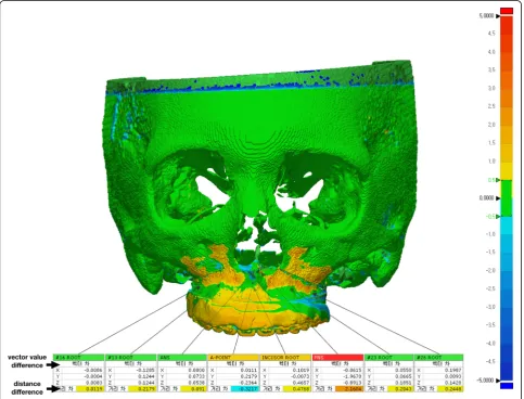
(T1) and VS (Tv) was measured (Fig. 5), and statistical
comparisons between the coordinate values of the refer-ence points were also investigated. Independent t-tests were used to compare values. Images were obtained at three time points (T1, T2, and T3) and then
superim-posed (Fig.6). The three groups (T1 and T2, T2 and T3,
T1 and T3) were compared to assess the postoperative
Fig. 4The coordinate value of each reference point at (a) T0, (b) Tv and (c) T1
stability of the maxilla. One-way ANOVA with Tukey’s multiple comparison tests was used for comparisons among the three groups. Data were analyzed using the Statistical Package for Social Sciences (SPSS, version
23.0, IBM Co., Armonk, NY, USA). P-values less than
0.01 were considered significant.
Results
Satisfactory clinical outcomes were achieved in all pa-tients, and VS was successfully reproduced in the actual surgery for all patients. All 13 patients were also satisfied by the postoperative results, including the occlusion and facial profile. No complications, such as malocclusion, tooth loss, sensory disturbance of the infraorbital nerve or infection, occurred during the follow-up period. The
differences between ΔTv (Tv-T0) and ΔT1 (T1-T0) are
shown in Table 2. There were no significant differences
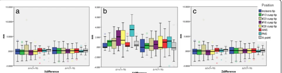
between the time points (Fig. 7). The Tv and T1
coord-inate values for the bone reference points and the direct
distances are shown in Table 3. There were no
signifi-cant differences among the coordinate values. The mean distance difference at all reference points between Tv
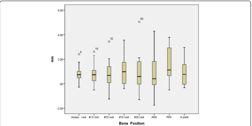
and T1 was 1.01 ± 0.3 mm (Fig. 8). The greatest
difference was at the PNS, although the difference was not significant. There were no significant differences among the three groups (T1 and T2, T2 and T3, T1 and T3) regarding the stability of the maxilla. The mean
dif-ference between T1 and T3 was −0.37 ± 0.29 mm
(Table4) (Fig.9).
Discussion
In this study, we report virtual surgical simulation with FaceGide® incorporating PCGs (including drilling holes for screws), PCMs and a customized final splint. In our series, the surgical transfer of the VSP by FaceGide® showed good accuracy, and the final position of the maxilla measured at the points associated with the root of the tooth (bone surface) was 0.94 ± 0.17 mm from the mean value. The ANS, PNS, and A point may show large differences between Tv and T1 because they are the sites of bone removal during the actual operation. However, the error was still approximately 1.01 ± 0.3 mm, even when these points were included.
With the introduction of CBCT, which reduces the hardware costs and radiation doses, 3D imaging can be used as a standard tool for diagnosis and treatment
Fig. 6Comparison of reference points located on the bone surface after the superposition of (a) T1 and T2 images, (b) T2 and T3 images and (c) T3 and T1 images
Table 2Distance difference betweenΔTv (Tv-T0) andΔT1 (T1-T0)
ΔXv (Tv-T0) ΔX1 (T1-T0) ΔYv (Tv-T0) ΔY1 (T1-T0) ΔZv (Tv-T0) ΔZ1 (T1-T0)
n Average SD Average SD p Average SD Average SD p Average SD Average SD p
Incisor tip 13 −0.004 2.097 0.003 2.293 0.994 0.468 1.075 0.216 1.426 0.616 0.034 0.370 1.166 1.649 0.024
#13 cusp tip 13 −0.059 1.909 −0.071 2.075 0.988 0.910 1.042 0.271 1.226 0.165 0.148 0.522 1.334 1.515 0.014
#23 cusp tip 13 0.790 3.522 −0.026 2.126 0.482 0.996 1.636 0.491 1.770 0.458 0.019 0.664 1.044 1.921 0.082
#16 cusp tip 13 −0.161 1.603 −0.257 1.731 0.885 1.843 1.759 0.509 1.482 0.047 0.397 0.702 1.494 1.385 0.018
#26 cusp tip 13 −0.083 1.571 −0.190 1.716 0.87 1.940 2.018 0.756 2.386 0.185 0.224 0.867 1.051 2.002 0.185
ANS 13 −0.042 1.598 −0.045 1.576 0.997 0.661 0.988 0.730 1.470 0.89 1.655 1.442 1.177 1.805 0.462
PNS 13 −0.178 1.080 0.092 0.882 0.492 3.263 1.736 1.100 2.428 0.015 1.723 1.487 1.618 1.508 0.859
A point 13 −0.027 1.518 −0.016 1.539 0.99 0.767 0.950 −0.107 2.054 0.18 1.409 1.250 1.447 1.093 0.94
planning [16]. Although it is possible to obtain much in-formation from this 3D diagnostic method, the IMS is generally used in conventional bimaxillary OGS. In-creased use of the IMS can cause postoperative prob-lems because the inherent thickness of the splint may
result in a degree of autorotation after the splint’s
re-moval [17]. Additionally, Perez et al. reported that the
temporomandibular joint (TMJ) is not a discrete ball-and-socket joint. The mandibular condyle rotates
and translates within the TMJ [18]. Therefore,
reposi-tioning the maxilla in relation to the position of the mandible may have several limitations. The mandible and maxilla can be fixed together with an IMS during OGS, but a certain amount of space can develop as a re-sult of the mobility of the mandibular condyle. There-fore, the maxilla cannot be precisely positioned relative to the base of the skull using only an IMS, and the sur-geon must take time to adjust it manually. In addition, inaccuracy of the IMS can arise from the model surgery stage. Model surgery depends on the accurate recording of the occlusion in the retruded position and the face-bow transfer to the articulator. These recordings both have inherent inaccuracy. Baily et al. measured the angulation of the occlusal plane to the Frankfort plane on a Hanau articulator and compared this with lateral cephalograms; they found a mean difference of 5 de-grees, which corresponded to 70% of the error during
the face-bow transfer [19]. Ellis et al. reported that the
average case had an inaccuracy of almost 7 degrees in
the angulation of the occlusal plane [20]. The accuracy
of the 3D position of the upper first molar was highly
variable using four different Hanau face-bows [21].
When using a conventional articulator for OGS, it is es-sential that the angle between the occlusal plane and the Frankfort horizontal plane for the patient is the same as the angle between the occlusal plane and the upper member of the articulator on the maxillary model. OGS using the FaceGide® system can reduce errors related to
mock surgery because it does not use such an articulator during preoperative preparation.
The surgical method presented in this study using the FaceGide® system is not necessary for all patients with craniofacial deformity. Rustemeyer et al. reported that a 2D cephalometric analysis and a 3D mock operation are sufficient for accurate planning and will ensure good
re-sults for experienced surgeons [22]. We agree with this
opinion, and if the patient has no facial asymmetry or requires only single-jaw surgery, conventional OGS can produce good results. However, if major 3D movements are indicated, including changes to the transverse occlu-sal plane or major rotation of the jaws, a navigation sys-tem should be chosen for complex 3D planning and controlling the position of the maxilla during surgery
[23]. Most of the patients in this study had facial
asym-metry. Therefore, the use of the FaceGide® system was recommended for surgery, and complex 3D movement of the jaws was performed. Our method of OGS using the FaceGide® system is very original, albeit not new. The principle of the FaceGide® system that we present is based on the combination of previously mentioned pro-cesses and is associated with predrilling determined by a
reverse approach [24]. In a study by Xia et al., the final
state was made into a medical replica after the VS, and the ready-made plates were bent according to the out-line of this replica. During the actual operation, drilling for screw insertion was performed using the navigation
system [24]. Use of the FaceGide® system is the same as
the reverse approach of that reported by Xia et al., but customized miniplates and corresponding osteotomy guides (including drilling guides) are used. Similar pro-cesses involving predrilling and positioning osteotomy guides or prebent plates in OGS have been reported
[25–28].
Ellis reported that the average accuracy of maxillary positioning in the horizontal plane deviated 2 mm from what was planned when external references were used,
Fig. 7(a) Difference betweenΔXv andΔX1 on the X-axis. There was no significant difference between the two groups. (b) Difference between
whereas the vertical accuracy ranged from 0.5 to 1 mm
[29]. Jacobson et al. reported that a 2-mm or greater
dis-crepancy was noted for 20 to 30% of 46 patients who
underwent LeFort I osteotomy [30]. With the
develop-ment of CAD and CAM, VSPs and 3D-printed naviga-tion templates have been proposed as alternatives to
conventional model surgery [31]. Sun et al. performed a
clinical study using an orthognathic surgical template made from a 3D printer and VSP and reported that the mean vertical, lateral, and anteroposterior errors in the anterior maxillary region were 0.57 mm, 0.35 mm, and
0.5 mm, respectively [32]. Although our study shows a
higher error than that of Sun et al.’s study, the difference
may have been due to the use of different measurement methods, and our error was smaller than that reported
in previous studies [29, 30] that used conventional
methods. During the entire process, errors in surface
rendering, data integration (merging dentition and CBCT data), and setting 3D coordinates in the virtual space or during guide, surgical splint and miniplate fab-rication (3D printing or milling process) are related to accuracy. Accuracy can be improved with the use of a systemic process during surgical planning and prepar-ation. Zinser et al. reported that the mean vertical, lat-eral, and anteroposterior errors compared with the anterior maxillary region were 0.23 mm, 0.04 mm, and 0.09 mm, respectively, and that the vertical, lateral, and anteroposterior errors compared with the posterior max-illary region were 0.15 mm, 0.04 mm, and 0.1 mm,
re-spectively [33]. Our results are not comparable because
we did not use the same measurement approach that was used by Zinser et al. However, in our study, the dif-ferences between the VS and the actual surgery were
0.26 mm, 0.47 mm, and 1.11 mm in the anterior
Fig. 8Differences between Tv and T1 at each bone reference point
Table 4Distance difference between T1 and T2, T2 and T3, and T1 and T3
T1 and T2 T2 and T3 T1 and T3
N Average SD Average SD Average SD p
Incisor root 13 −0.109 1.037 −0.117 0.237 −0.529 0.982 0.352
# 13 root 13 0.393 0.930 −0.044 0.236 −0.165 0.617 0.089
#23 root 13 0.271 0.556 −0.057 0.197 −0.145 0.680 0.113
#16 root 13 −0.053 0.591 −0.016 0.183 −0.138 0.896 0.880
#26 root 13 0.354 1.066 0.010 0.322 −0.446 1.389 0.153
ANS 13 −0.823 1.811 −0.105 0.496 −0.821 1.449 0.316
PNS 13 0.083 0.770 −0.179 0.623 −0.043 0.845 0.741
maxillary region (incisor tip, #13 cusp tip and #23 cusp tip) and 0.02 mm, 1.6 mm, and 0.6 mm in the posterior maxillary region (#16 cusp tip, #26 cusp tip and PNS).
We are aware that this study may have limitations. The small number of patients in this retrospective study limits the ability to draw definite conclusions. One rea-son for the small sample size was the utilization of strict inclusion and exclusion criteria, which resulted in the exclusion of the majority of patients who underwent OGS in the department during the study period. How-ever, image analysis using 3D comparison programs is highly reproducible and can yield significant results even with a small number of cases. There were some trial and error in the operation using the FaceGide® system. There
were no significant differences between ΔTv and ΔT0,
but in some cases, the Y coordinate value of the PNS was somewhat different from that of the other sites. Therefore, even when the operation is performed using this system, more attention should be paid when the posterior part of the maxilla is moved. In three patients,
the maxilla was unstable after fixation, so the
ready-made miniplates were added for reinforcement. In some cases in which the surgeon was unfamiliar with the newly developed system, wide-diameter screws were used because of a widening of the holes after drilling. However, this problem could be solved by drilling with a small-diameter round burr and self-drilling screws. PCGs with an arm that originates from the cusp of the teeth can also confirm the accuracy of the bone contact
(Fig. 2). Minor mispositioning of the PCGs is impossible
to detect by the naked eye and can result in erroneous cuts. Therefore, this type of PCG is believed to be more accurate than a bone-only supported guide because it is supported by both the bone surface and the cusp of the
teeth, but further research regarding its accuracy is needed. The accuracy of OGS using CASS is influenced by reproduction of the VS in the actual surgery. Individ-ual errors can originate from internal sources, including the CBCT image quality, file conversion process, com-puter design software, and interactions between mech-anical components, and external sources, such as the adaption of the osteotomy guide, customized plate, and
splints and the surgeon’s experience. The accumulation
of such errors produces the total deviation between the planned and postoperative outcomes. However, this study demonstrates the suitable accuracy and stability of OGS using the FaceGide® system.
The facial surgery protocol using FaceGide® has advan-tages similar to those of other CASS systems. Digital diagnosis and VS data files can be transmitted to the
surgeon and orthodontists for final adjustments [33].
Such exchanges have the advantage of allowing the cre-ation of an interdisciplinary platform that centralizes the technical and surgical domains of expertise and pro-duces financial and operative efficiency, all within a
digital environment [31]. Because the site of the bone
screw insertion is designed to avoid the root of the tooth, it is unlikely that root damage will occur when conventional methods are used. Some clinicians may claim that using CASS can expose the patient to
in-creased radiation [34]. However, it can eliminate the
need for additional radiographic examinations, which is indicated when there are doubts about the final surgical position. It is well known that the radiation dose of most CBCT systems used to acquire DICOM data is
considered minimal [35]. There have been reports of
the use of one piece of customized plate in the
max-illa that have claimed accuracy [36–38]. However, the
body reaction. The volume of titanium used in our study is equal to or less than the volume of titanium used in the conventional fixation method of LeFort I osteotomy. Although not reported in this study, the PCMs were removed in three patients one year after surgery and did not cause clinical problems. Future studies involving PCM removal will be conducted. Unlike conventional surgery, the use of PCGs in our study allowed us to remove the necessary amount of bone, thereby increasing contact between bone seg-ments. Our method was less invasive than conven-tional methods, and the patients recovered rapidly and were able to return quickly to normal life.
Conclusions
The maxillary bone should be positioned according to a planned position during OGS to achieve a successful op-eration. We performed OGS using the FaceGide® system, which is a newly developed CASS system. The reposi-tioning of the maxilla was clinically accurate, and stable results were maintained one year after the operation. Currently, the quality of the surgical result still depends on the skill of the individual surgeon in carrying out the surgical plan. However, surgeons with average experi-ence will be able to achieve acceptable treatment results using the FaceGide® system (via a VSP and manufactur-ing of the related materials). In other words, 3D evalu-ation, virtual simulevalu-ation, and CAD-CAM technology can benefit both doctors and patients. The development of digital technologies will continue to support the adop-tion of computer-assisted techniques in medicine and dentistry.
Abbreviations
3D:Three-dimensional; CAD: Computer-aided design; CAM: Computer-aided manufacturing; CASS: Computer-aided surgical simulation; CBCT: Cone beam computed tomography; CNC: Computer numerical control; CR: Centric relation; IMS: Intermediate splint; OGS: Orthognathic surgery; PCG: Patient-customized osteotomy guide; PCM: Patient-Patient-customized miniplate; SD: Standard deviation; STL: Surface tessellation language; VSP: Virtual surgical plan; VTO: Visual treatment objective
Acknowledgments
We would like to thank Dr. Jun-Young You, Ph.D., (Director of“Gnatho Oral and Maxillofacial Surgery Clinic,”Seoul, Republic of Korea) for advice on the reorientation method based on CBCT and OGS.
data, and KJC, SWC, and IYP analyzed and interpreted all the data; together, they were the major contributors to preparing and writing the manuscript. CGJ acquired data with the FaceGide® program and the PolyWorks Inspector™program. BEY performed the statistical evaluation and revised the manuscript before submission. All the authors have read and approved the final manuscript.
Ethics approval and consent to participate
This study protocol was approved by the Hallym University Sacred Heart Hospital Institutional Review Board (IRB No. 2018–06-016). IRB approved this retrospective study, and informed consent was waived by the study subjects because all the patient data were anonymized and de-identified before the analysis.
Consent for publication
Not applicable.
Competing interests
The authors declare that they have no competing interests in relation to the present work.
Publisher’s Note
Springer Nature remains neutral with regard to jurisdictional claims in published maps and institutional affiliations.
Author details
1
Division of Oral and Maxillofacial Surgery, Hallym University Sacred Heart Hospital, 11, Gwanpyeong-ro 170beon-gil, Dongan-gu, Anyang-si, Gyeonggi-do, 14066 Anyang, Republic of Korea.2Mir Dental Hospital, 12
Gongpyoungro Jung-gu Daegu, 41940 Daegu, Republic of Korea.3Division of
Orthodontics, Hallym University Sacred Heart Hospital, Anyang, Republic of Korea.4Graduate School of Clinical Dentistry, Hallym University, Chuncheon,
Republic of Korea.5Institute of Clinical Dentistry, Hallym University,
Chuncheon, Republic of Korea.
Received: 1 October 2018 Accepted: 4 January 2019
References
1. Joshi N, Hamdan AM, Fakhouri WD. Skeletal malocclusion: a developmental disorder with a life-long morbidity. J Clin Med Res. 2014;6:399.
2. Luhr H, Kubein-Meesenburg D. Rigid skeletal fixation in maxillary osteotomies. Intraoperative control of condylar position Clin Plast Surg. 1989;16:157–63.
3. Polido WD, Ellis E, Sinn DP. An assessment of the predictability of maxillary repositioning. Int J Oral Maxillofac Surg. 1991;20:349–52.
4. Stokbro K, Aagaard E, Torkov P, Bell R, Thygesen T. Virtual planning in orthognathic surgery. Int J Oral Maxillofac Surg. 2014;43:957–65. 5. Ellis E. Accuracy of model surgery: evaluation of an old technique and
introduction of a new one. J Oral Maxillofac Surg. 1990;48:1161–7. 6. Harris M, Hunt N. Fundamentals of orthognathic surgery and non surgical
facial aesthetics. 3rd ed: World Scientific; 2018.
7. Yohn K. The face bow is irrelevant for making prostheses and planning orthognathic surgery. J Am Dent Assoc. 2016;147:421–6.
8. Bowley JF, Michaels GC, Lai TW, Lin PP. Reliability of a facebow transfer procedure. J Prosthet Dent. 1992;67:491–8.
10. Zizelmann C, Hammer B, Gellrich N-C, Schwestka-Polly R, Rana M, Bucher P. An evaluation of face-bow transfer for the planning of orthognathic surgery. J Oral Maxillofac Surg. 2012;70:1944–50.
11. Boucher L, Jacoby J. Posterior border movements of the human mandible. J Prosthet Dent. 1961;11:836–41.
12. McMillen LB. Border movements of the human mandible. J Prosthet Dent. 1972;27:524–32.
13. Gelesko S, Markiewicz MR, Weimer K, Bell RB. Computer-aided orthognathic surgery. Atlas Oral Maxillofac Surg Clin North Am. 2012;20:107–18. 14. Zhang W, Li B, Gui H, Zhang L, Wang X, Shen G. Reconstruction of complex
mandibular defect with computer-aided navigation and orthognathic surgery. J Craniofac Surg. 2013;24:e229–e33.
15. Kim JW, Kim JC, Cheon KJ, Cho SW, Kim YH, Yang BE. Computer-aided surgical simulation for yaw control of the mandibular condyle and its actual application to orthognathic surgery: a one-year follow-up study. Int J Environ Res Public Health. 2018;15.
16. Mah J: The genesis and development of CBCT for dentistry. In.; 2014. https://www.semanticscholar.org/paper/The-Genesis-and-Development-of-CBCT-for-Dentistry/11ffda347e7b4348865ef5535e1506c6491b9022. 17. Bryan DC, Hunt NP. Surgical accuracy in orthognathic surgery. Br J Oral
Maxillofac Surg. 1993;31:343–9 discussion 9-50.
18. Perez D, Ellis E. Sequencing bimaxillary surgery: mandible first. J Oral Maxillofac Surg. 2011;69:2217–24.
19. Bailey J, Nowlin T. Accuracy of the Frankfort plane transfer to the Hanau articulator. J Dent Res. 1981:531.
20. Ellis E, Tharanon W, Gambrell K. Accuracy of face-bow transfer: effect on surgical prediction and postsurgical result. J Oral Maxillofac Surg. 1992;50: 562–7.
21. O’malley A, Milosevic A. Comparison of three facebow/semi-adjustable articulator systems for planning orthognathic surgery. Br J Oral Maxillofac Surg. 2000;38:185–90.
22. Rustemeyer J, Groddeck A, Zwerger S, Bremerich A. The accuracy of two-dimensional planning for routine orthognathic surgery. Br J Oral Maxillofac Surg. 2010;48:271–5.
23. Santler G. 3-D COSMOS: a new 3-D model based computerised operation simulation and navigation system. J Craniomaxillofac Surg. 2000;28:287–93. 24. Xia JJ, Gateno J, Teichgraeber JF. A new paradigm for complex midface
reconstruction: a reversed approach. J Oral Maxillofac Surg. 2009;67:693–703. 25. Olszewski R, Tranduy K, Reychler H. Innovative procedure for
computer-assisted genioplasty: three-dimensional cephalometry, rapid-prototyping model and surgical splint. Int J Oral Maxillofac Surg. 2010;39:721–4. 26. Polley JW, Figueroa AA. Orthognathic positioning system: intraoperative
system to transfer virtual surgical plan to operating field during orthognathic surgery. J Oral Maxillofac Surg. 2013;71:911–20. 27. Dérand P, Rännar L-E, Hirsch J-M. Imaging, virtual planning, design, and
production of patient-specific implants and clinical validation in craniomaxillofacial surgery. Craniomaxillofac Trauma Reconstr. 2012;5:137. 28. Zhou LB, Shang HT, He LS, Bo B, Liu GC, Liu YP, et al. Accurate
reconstruction of discontinuous mandible using a reverse engineering/ computer-aided design/rapid prototyping technique: a preliminary clinical study. J Oral Maxillofac Surg. 2010;68:2115–21.
29. Ellis E. Bimaxillary surgery using an intermediate splint to position the maxilla. J Oral Maxillofac Surg. 1999;57:53–6.
30. Jacobson R, Sarver DM. The predictability of maxillary repositioning in LeFort I orthognathic surgery. Am J Orthod Dentofac Orthop. 2002;122:142–54. 31. Xia JJ, Phillips CV, Gateno J, Teichgraeber JF, Christensen AM, Gliddon MJ, et
al. Cost-effectiveness analysis for computer-aided surgical simulation in complex cranio-maxillofacial surgery. J Oral Maxillofac Surg. 2006;64:1780–4. 32. Sun Y, Luebbers H-T, Agbaje JO, Schepers S, Vrielinck L, Lambrichts I, et al.
Accuracy of upper jaw positioning with intermediate splint fabrication after virtual planning in bimaxillary orthognathic surgery. J Craniofac Surg. 2013; 24:1871–6.
33. Zinser MJ, Mischkowski RA, Sailer HF, Zöller JE. Computer-assisted orthognathic surgery: feasibility study using multiple CAD/CAM surgical splints. Oral Surg Oral Med Oral Pathol Oral Radiol. 2012;113:673–87. 34. Yeh J-K, Chen C-H. Estimated radiation risk of cancer from dental
cone-beam computed tomography imaging in orthodontics patients. BMC oral health. 2018;18:131.
35. Bagheri SC, Jo C. Clinical review of Oral and maxillofacial surgery-E-book. Elsevier Health Sciences. 2013.
36. Mazzoni S, Bianchi A, Schiariti G, Badiali G, Marchetti C. Computer-aided design and computer-aided manufacturing cutting guides and customized titanium plates are useful in upper maxilla waferless repositioning. J Oral Maxillofac Surg. 2015;73:701–7.
37. Suojanen J, Leikola J, Stoor P. The use of patient-specific implants in orthognathic surgery: a series of 32 maxillary osteotomy patients. J Craniomaxillofac Surg. 2016;44:1913–6.
38. Heufelder M, Wilde F, Pietzka S, Mascha F, Winter K, Schramm A, et al. Clinical accuracy of waferless maxillary positioning using customized surgical guides and patient specific osteosynthesis in bimaxillary orthognathic surgery. J Craniomaxillofac Surg. 2017;45:1578–85. 39. Hosoki M, Nishigawa K, Miyamoto Y, Ohe G, Matsuka Y. Allergic contact