Jun Jae Lee 9 Jung Pyo H o n g
Study on half-scale model test for light-frame shear wall
Received: February 21, 2001 / Accepted: October 15, 2001
Abstract A half-scale model of a light-frame shear wall was developed to evaluate the racking performance of a full- scale shear wall (prototype). The effect of nail size on the performance of the shear wall was also investigated using models constructed with three types of nail. Materials for the model were determined through experimental methods, which included nail-head push-through, stud-to-sheathing nail connection, and static bending tests. Materials with which the model was made to be "in similarity" to the prototype were three-layer 4.8-mm plywood, 39.72-mm long nails, and 1 • 2 lumber cut from 2 • 4 studs. In accordance with ASTM E 72 and ASTM E 564, racking resistance tests were conducted on 20 shear walls. The results showed that the maximum load capacities of the prototype walls could be evaluated by the model without significantly different failure modes. Tests on the effect of nail size revealed that increasing the nail head diameter may improve the performance of shear walls.
Key words Half-scale model 9 Light-frame shear wall - Similarity 9 Racking resistance
Introduction
For several decades the racking performance of light-frame shear walls against lateral forces have been evaluated by various methods,1-5 and the accumulated data have been used as the basic criteria in many fields of wooden construc-
J.J. Lee ( ~ ) 9 J.P. Hong
College of Agriculture and Life Sciences, Seoul National University, Suwon 441-744, Korea
Tel. +82-31-290-2603; Fax +82-31-293-9376 e-mail: [email protected]
Parts of this paper were presented at the International Conference on Effective Utilization of Plantation Timber (ICEUPT'99), Chi-Tou, Taiwan, May 1999; and the World Conference on Timber Engineering (WCTE2000), Whistler, Canada, July-August 2000
tion. Most of the data, however, were based on the results of 2.4 • 2.4m test specimens, illustrated in ASTM E 72. 6 In recent years wooden structures are becoming multistoried and larger in scale by the aid of construction technologies and structural engineered wooden products. Thus, shear walls are becoming larger along with the introduction of openings in various shapes. Therefore, there is an increasing need to investigate the performance of large shear walls. 7-1~ The performance of the shear walls longer or higher than 2.4m have been evaluated by simulation and full-scale test- ing that requires not only huge test facilities but also much time, manpower, and cost. These tests are not sufficient because of the specimen sizes and the testing facilities. 11 Also, neither analytical nor numerical models can give pre- cise results on the failure loads, load deformation relations, or failure modes. This kind of information can be achieved only by conducting tests on modeled test specimens.
In this study, to obtain the desired results and also to avoid these disadvantages, a half-scale model test was adopted to evaluate the performance of light-frame shear walls. The model walls were developed by means of experi- mental methods, and the racking resistance tests were performed on the model and the prototype. During the process of determining the most advantageous materials for the model, the effects of nail length, head diameter, and shank diameter on the performance of a shear wall were investigated.
Theoretical background
The small-scale model is a test specimen reduced in size to investigate the full-scale structure. The small-scale model test is defined as experimental analysis of the actual struc- tural system through use of a miniature m a n u f a c t u r e d so it has similarity (similitude) to the prototype. T h e term "simi- larity" accounts for the relation between model and proto- type. The similarity can be checked by comparing each value of the variables involved in the dimensionless param- eters of the model and the p r o t o t y p e (Eq. 3). Based on the B u c k i n g h a m pi (7c) theorem, the dimensionless p a r a m e t e r is derived f r o m dimensional analysis with the variables re- lated to a behavior of a structure. W h e n the involved model values of variables can equate the model p a r a m e t e r to the p r o t o t y p e parameter, the model is regarded as being in similarity to the prototype.
Because the dimension of the governing equation for a physical p h e n o m e n o n is identical in model and proto- type, physical variables xi can be expressed by the following equation.
F(Xl,xz,X3...xn)= 0
(1)
Applying the B u c k i n g h a m Jr theorem, this equation can be rewritten using the dimensionless zc parameters as follows.
G(TVt,~z,TC3 ...
~,~) =
0(2)
where 7c i is the dimensionless p a r a m e t e r containing n physi- cal variables (xi); m is n - r; and r is the n u m b e r of funda- mental dimensions: for the static condition, force (F) and length (L) are involved; for the dynamic condition, force (F), length (L), and time (T) are involved.
In a small-scale model test for structures, the variables involved in static behaviors of a structure are force (Q), length (L), and modulus of elasticity (E). Using the dimen- sionless p a r a m e t e r for Q, 7co- can be found with the follow- ing equation.
where P is the prototype; and rn is the small-scale model. Therefore, according to the scale ratio, the force involved in the model can be derived from Eqs. (4), (5), and (6).
QP = So- (4)
Qm
where So- is the scale ratio for force.
E#2~ - SES~
(5)
where SE is the scale ratio for the modulus of elasticity; and Sl is the scale ratio for the length.
Assuming that both moduli of elasticity are identical (SE = 1)
Qm - Qp -
QP
So
ses~
(6)It therefore can be concluded that the force of the model is the force of the p r o t o t y p e divided by the square of the linear scale ratio. For example, if the linear scale ratio is 2, as in this study, to c o m p a r e the model with the p r o t o t y p e directly, the values of the half-scale model test results should be multiplied by 4 for force and 2 for length.
Determination of materials for half-scale model
Scale ratio
Because w o o d as a structural material has m a n y defects, such as knots, grain, and anisotropic properties, it is difficult to manufacture small-scale materials of w o o d e n structures artificially and retain the required properties. Furthermore, over-downscaling m a y create m a n y problems, such as am- plifying the effect of w o o d defects, splitting of w o o d in connections, and deformation of the m e m b e r s caused by drying stress. To minimize these problems, a half-linear downscale ratio was selected for this study.
Materials
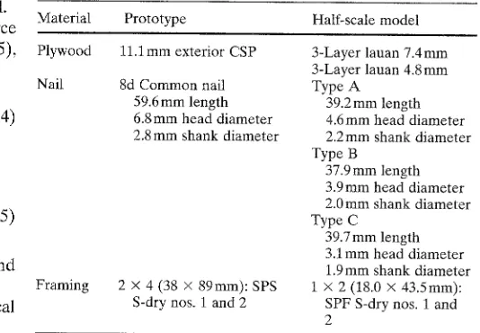
Table 1 shows the details for the materials used in the half- scale model and the prototype. In plywood-sheathed shear walls previously studied by other investigators, the failure modes of racking resistance tests were pronounced, mani- festing primarily as nail slip, nail-head pull-through, and panel edges breaking off. 1'3's On the basis of these results, the experimental methods to determine the small-scale materials were established: the nail-head push-through test 13 and the stud-to-sheathing nail connection test. 14 Com- mercially available materials were used tentatively for the model because it was impossible to adjust the properties of
Table 1. Materials for the prototype and tentative materials for the half-scale model
Material Prototype Half-scale model Plywood 11.1 mm exterior CSP 3-Layer lauan 7.4 mm
3-Layer lauan 4.8 mm
Nail 8d Common nail Type A
59.6mm length 39.2mm length 6.8mm head diameter 4.6mm head diameter 2.8 mm shank diameter 2.2 mm shank diameter
Type B 37.9 mm length 3.9ram head diameter 2.0mm shank diameter Type C
39.7mm length 3.1mm head diameter 1.9ram shank diameter Framing 2 • 4 (38 • 89mm): SPS 1 • 2 (18.0 • 43.5mm):
the solid wood, and in the case of nails the manufacturing cost was too high to m a k e a special order.
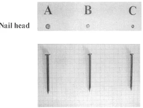
T w o types of p l y w o o d (7.4 and 4.Smm thick) and three types of nail (Fig. 1) were selected as tentative materials for the model according to their geometric similarity. T h e com- bination (or assembly) of nail and plywood in a model showing the most similarity to that of the prototypes was determined as the small-scale materials based on the maxi- m u m load capacity resulted f r o m the nail-head push- through test and the stud-to-sheathing nail connection test. Small-scale studs were m a n u f a c t u r e d from the 1 • 2 lum- bers cut from 2 • 4 studs. Then the small-scale studs were checked for their suitability through the static bending test with five replications. 15
Materials for the model
T h e results from the above two tests showed that the type C nail and 4 . 8 m m thick p l y w o o d (combination 5-C) were the most appropriate materials for the model (Table 2). T h e
results of the static bending test revealed that there was no significant difference in the modulus of elasticity ( M O E ) between 2 • 4 studs and i • 2 studs (average M O E 112000 and 108 000 kg/cm 2, respectively). The 16d c o m m o n nail connecting the plate to the stud was excluded from the model material-determining tests because its contribution to the shear wall capacity is relatively small c o m p a r e d to the other materials. Furthermore, because of the difficulty manufacturing a small-scale model, such as splitting of the plates induced by nail driving, only the small-scale nails used for stud-to-sheathing connections were driven in all connections of model walls. N o t e that in Table 2 the listed values of the combination of tentative models were four times the measured values.
Shear wall construction
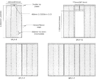
Figure 2 illustrates the four wall configurations (1PLY-F, 2PLY-F, 3PLY-F, 2 P L Y - O ) studied. Based on the geomet- ric similarities the wall sizes, nail spacings, and stud spacings in the models were downscaled by exactly one-half. Two or three test specimens were prepared for each wall configura- tion; 4 . 8 m m thick plywood panels and type C nails were used to construct the model. It should be noted that only one type of small-scale nail was used for all connections of the model. All panels used in the p r o t o t y p e were 1.2 • 2.4m (length x height) and were attached vertically to the frame. All nails, in the model and the prototype, were hand-driven. Table 3 gives the specifications of the wall constructions. Additionally, to investigate the effects of nail sizes, small- scale 2 P L Y - F walls were constructed using type A, B, and C nails.
Fig. 1. Three tentatively chosen nails for the model
Racking resistance test
To simplify b o u n d a r y conditions, test facilities were pre- pared in accordance with A S T M E 72 (Fig. 3). 6 Using a hydraulic loader, a static m o n o t o n i c load as described in A S T M E 564 I6 was applied to the timber loader, which was bolted on the top plate of the wall. T h e load rate was
Table 2. Comparison of maximum load capacity from the two tests used to determine materials for the model
Specimen Repetitions Maximum load (kN) a
Nail-head push- through test
Stud-to-sheathing nail connection test
Prototype 5 1.31 2.91
Combination of tentative models b
5-A 5 2.03 5.97
5-B 5 1.72 3.90
5-C 5 1.50 2.71
7-A 5 3.46 6.82
7-B 5 2.53 5.37
7-C 5 1.69 4.27
aMaximum load values of models are listed as four times the measured value
Fig. 2. Light-frame shear wall configurations
oE
E
1,220mm(610mm)
i
.dr ~ - Double top plates
406ram O.C(203mm O.C)
152mm(76mm) : e d g e
305mm(152.5mm) :intermediate
o E E o c,J
1 P L Y - F 2 P L Y - O
775mm(387.5mm)
2 P L Y - F 3 P L Y - F
* The values in blanks are sizes of 1/2 small-scale model.
* Note that two nails are driven in each connection of s t u d - t o - b o t t o m plate, and four nails consisting of 2 layers, in each connection of s t u d - t o - d o u b l e top plates.
Table 3. Framing, sheathing, and nails for shear walls
Materials Prototype Half-scale model
Framing
Stud, plate 2 • 4 SPF S-dry nos. 1 and 2 Double top plate/single bottom plate Stud at 406mm O.C
Sheathings
11.lmm Exterior CSP (1.2m x 2.4m) Nail
8 d common nail (stud-to-sheathing) 16d common nail (stud-to-plate) Nail schedule: 152/305 mm (edge/field)
1 • 2 Cut from prototype stud Double top plate/single bottom plate Stud at 203mm O.C
4.Smm plywood (0.6 • 1.2m)
All half-scale nails (stud-to-sheathing, plate)
Nail schedule: 76.0/152.5 mm (edge/field)
Sensor Sensor
Fig. 3. Racking resistance test setup
Up/down
motor
0 . 2 m m / s . F o u r s t r a i n gauges b a s e d o n t r a n s d u c e r s w e r e p o s i t i o n e d to m o n i t o r t h e h o r i z o n t a l d i s p l a c e m e n t , b o t t o m slip, uplift, a n d vertical d i s p l a c e m e n t a u t o m a t i c a l l y at 0.5-s intervals.
Results and discussion
S i m i l a r i t y e r r o r of m a t e r i a l s
S i m i l a r i t y e r r o r was c a l c u l a t e d with t h e f o l l o w i n g e q u a t i o n .
(value of m o d e l x c o r r e s p o n d i n g S i m i l a r i t y _ scale ratio) - ( v a l u e of p r o t o t y p e )
e r r o r - v a l u e of p r o t o t y p e x 100(%)
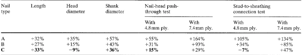
Table 4. Similarity errors in part sizes of three nail types and maximum load capacity from two material-determining tests
Nail Length Head Shank Nail-head push- Stud-to-sheathing
type diameter diameter through test connection test
With With With
4.8mm ply. 7.4mm ply. 4.Smm ply.
With 7.4 mm ply.
A +32% +35% +57% +55% +164% +105% +134%
B +27% +15% +43% +31% +93% +34% +85%
C +33% -9% +36% +15% +29% -7% +47%
ply., plywood
Table 5. Results of racking resistance tests for models constructed with type A, B, and C nails
Wall type Repetition Maximum load Primal failure mode
(kN)
2PLY-F-A 1 13.21 Panel breaking off, nail pull-out
2PLY-F-B 1 10.04 Panel breaking off, nail pull-out, two nail-head pull-through
2PLY-F-C 1 4.78 Nail-head pull-through, panel breaking off, nail pull-out
Table 4 shows the geometric similarity errors in part sizes of the three nail types and similarity errors of maxi- mum load capacities resulting from the nail-head push- through test and stud-to-sheathing nail connection test. Nail type C showed the least geometric similarity errors: - 9 % in head diameter and +36% in shank diameter, but +33% in length. The combination of nail type C and 4.8mm thick plywood also gave the least similarity error in the perfor- mance of the nail. The major difference between the three nail types lies in the nail-head diameter. It revealed that nail-head size might exert the greatest effect on nail perfor- mance for all parts of a nail, though the effects of the other parts of a nail were not negligible. This fact suggests that increasing the nail-head diameter may improve perfor- mance of a panel-frame assembly subject to failure of nail-head pull-through, such as a light-frame shear wall assembled with nails.
Effect of nail-head size on racking resistance of the shear wall in the model
Maximum load capacities and failure modes of the three model walls (2PLY-F-A, 2PLY-F-B, 2PLY-F-C) con- structed with nail types A, B, and C, respectively, are summarized in Table 5. The maximum load capacities of 2PLY-F-A wall (13.21kN) and 2PLY-F-B wall (10.04kN) were 176% and 110% greater than that of 2PLY-F-C (4.78kN), respectively. In the primal failure type, 2PLY-F- A failed by panel tearing and nail pull-out from the stud. However, nail-head pull-through did not occur in the wall. The reason for failure of 2PLY-F-B was similar to that of 2PLY-F-A except for two nail-head pull-throughs in the right upper corner of the left panel. The failure mode of 2PLY-F-C was a combination of panel tearing, nail pull-out, and nail pull-through, as reported previously. It shows that the wall constructed with 4.Smm thick plywood and the type C nail is a good model for the prototype. Furthermore,
these model tests indicate that the nail-head diameter has a considerable effect on the performance of a shear wall. When the racking load was applied, nail-head bearing on the panel commenced; then the nail head dug inside the panel, gradually crushing the panel. Finally, nail-head pull- through occurred. Therefore, it is thought that increasing the nail head diameter may improve the performance of a shear wall. However, further studies on the contribution of nail head size on the performance of a prototype shear wall are needed owing to the size effect and the relation between the applied load and the nail connection capacity in the prototype.
Checking similarity between shear walls
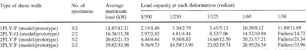
Table 6. Test results of prototypes and half-scale models ~
Type of shear walls No. of Average
specimens maximum
load (kN)
Load capacity at each deformation (radian)
1/500 1/250 1/125 1/60 1/30
1PLY-F (model/prototype) 3/2 2PLY-O (model/prototype) 2/2 2PLY-F (model/prototype) 3/2 3PLY-F (model/prototype) 2/2
11.87/12.31 2.19/1.49 3.30/2.79 5.45/5.13 1 0 . 3 9 / 8 . 1 2 11.89/11.89 16.38/15.38 2 . 9 7 / 2 . 8 3 4.81/4.44 8.53/7.06 1 4 . 5 2 / 1 0 . 9 4 Failure/14.72 20.62/21.53 6 . 4 4 / 6 . 6 4 9 . 5 8 / 8 . 8 3 1 4 . 6 8 / 1 2 . 5 0 2 0 . 2 1 / 1 7 . 2 1 Failure/21.34 29.62/33.98 9 . 3 6 / 9 . 7 3 1 4 . 5 9 / 1 3 . 9 0 2 3 . 0 2 / 1 9 . 7 4 2 8 . 9 5 / 2 6 . 5 4 Failure/33.96
aThe listed values for the half-scale model are four times the measured values
14.00
12.00
i o.00
cs
8.00
6.00
c 4.00 CE
2.00
0.00
2500 :
20.00 :
5.o o
~o.oo
+ m o d e l
5 O0
- - l - - p r o t o t y p e
Deformation (radian)
Fig. 4. Load-deformation relations of the model and prototype for
IPLY-F
0 O0
| model
[] prototype
J
J
Deformation (radian)
Fig. 6. Load-deformation relations of model and prototype for
2PLY-F
16.00
14.00 12.00
z
o lo.oo o 8,00
6.00
cc 4 . 0 0
2.00 0.00
/
~
odel[] prototype
9
J
Deformation (radian)
Fig. 5. Load-deformation relations of the model and prototype for
2PLY-O
35.00
3090
~z 2590
20,00
15.00
10 00
5.00
0.00
m prototype
9 J
Deformation (rad[an)
Fig. 7. Load-deformation relations of model and prototype for
3PLY-F
sorption of the nail connection was not considered. If materials with properties identical to those of the prototype were obtained for the model, a whole load-deformation curve of the prototype wall might be predicted through the model. Therefore, more studies on the methodology for obtaining small-scale materials are needed for wooden structures.
C o n c l u s i o n s
The racking performance of light-frame shear walls was evaluated using half-scale models. The effect of nail size on
the performance of shear walls was also investigated. Re- sults of this study indicate that the models may be used to predict the maximum load, initial shear stiffness, and failure mode of the prototype wall. However, the entire load- deformation curves derived from racking resistance tests of the model and prototype did not match satisfactorily. Tests on the effect of nail size revealed that using nails with a large head diameter to connect the sheathing panels to the framing members may be a good method for improving the performance of full-scale shear walls.
References
1. Tissell JR (1993) Structural panel shear wall. American Plywood Association Research Report 154
2. Patton-Mallory M, Gutkowski RM, Soltis LA (1984) Racking per- formance of light-frame walls sheathed on two sides. U S D A Forest Service research paper FPL448
3. Rose JD (1998) Preliminary testing of wood structural panel shear walls under cyclic (reversed) loading. A P A - The Engineered Wood Association, report 158
4. Itani RY, Tuomi RL, McCutcheon WJ (1982) Methodology of evaluate racking resistance of nailed walls. For Prod J 32(1):30-36 5. Ge YZ, Gopalaratnam VS, Liu H (1991) Effect of openings on the
stiffness of wood frame walls. For Prod J 41(1):65-70
6. American Society for Testing and Materials (1995) Standard test methods of conducting strength test of panels for building construction. ASTM E 72-95. American Society for Testing and Materials, Philadelphia
7. Johnson AC, Dolan JD (1996) Performance of long shear walls with openings. In: Proceedings of International Wood Engineering Conference 96, vol 2, pp 337-344
8. Lam F, Prion HGL, He M (1997) Lateral resistance of wood shear walls with large sheathing panels. J Struct Eng ASCE 123:1666- 1673
9. Ming H, Magnusson H, Lam F, Priori HGL (1999) Cyclic perfor- mance of perforated wood shear walls with oversize OSB panels. J Struct Eng ASCE 125:10-18
10. Enjily V, Griffiths RD (1996) The racking of large wall panel. In: Proceedings of International Wood Engineering Conference 96, voI 2, pp 321-328
11. Harris H G (1980) Use of structural models as an alternative to full- scale testing. ASTM Special Technical Publication 702, pp 25- 44
12. Serrette RL, Encalada J, Juadines M, Hoang N (1997) Static rack- ing behavior of plywood, OSB, gypsum and fiberbond walls with metal framing. J Struct Eng ASCE 123:107%1086
13. Poo C, McNatt JD, Lambrechts S J, Gertner G Z (1988) Direct withdrawal and head pull-through performance of nails and staples in structural wood-based panel materials. For Prod J 38(6):19- 25
14. Kalkert RE, Dolan JD (1996) Behavior of 8-D nailed stud-to- sheathing connections. For Prod J 47(6):95-102
15. American Society for Testing and Materials (1994) Standard methods of static tests of lumber in structural sizes. ASTM D198-94. American Society for Testing and Materials, Philadelphia