IJEDR1702109
International Journal of Engineering Development and Research (
www.ijedr.org
)
627
FEA BASED ANALYSIS & OPTIMIZATION OF
SPACED SEQUENTIAL TUBE SHEET
Mihir K. Panchal
1, Bhumik B. Patel
2, Hardik Parmar
31
PG Student,
2Assistant Professor, Mechanical Department,
3Assistant Professor, Mechanical Department
Kalol Institute of Technology & Research Centre, Kalol, Gujarat Technological University, (India)
Silver Oak College of Engineering & Technology,Ahmedabad.
Abstract–Tube sheetare used as for multiple purpose, either they connecting tubes for Heat Exchanger or act as support for filter element. As design of tube sheet is very complex, as it interactswith the pressure vessel and the stresses it generates. The location where the tube sheet is attached, radial expansion of the vessel is halted; this creates bending stresses in the vicinity of the tube sheet, in the new design that is proposed there are 3 tube sheets spaced at equal intervals. The resulting stress profile will be increasingly complex. In this research the analysis of sequential tube sheet will fall under AS ME code, which recommends usage of FEA. Analysis and study the effect of tube sheet spacing on stress profile and optimize the structure with S pacing distance between tube sheets and Thickness of the tube sheet.
Keyword
–Tubesheet, Sequential Spaced Tubesheet, FE
Analysis of Sequential Spaced Tubesheet
I. I
NT RODUCTIONA tube sheet is a plate, sheet, or bulkhead which is perforated with a pattern of holes designed to accept pipes or tubes. These sheets are used to support and isolate tubes in heat exchangers and boilers or to support filter elements. Depending on the application, a tube sheet may be made of various metals or of resin composites or plastic. A tube sheet may be covered in a cladding material which serves as a corrosion barrier and insulator and may also be fitted with a galvanic anode. T ube sheets may be used in pairs in heat exchange applications or singularly when supporting elements in a filter. Tube sheets are also used on cartridge-type filter devices to support the individual filter elements. They are similar in design to the high heat boiler varieties except they are typically made of resin composites or plastic and are generally used as single units. There are usually fewer tubes involved in a filter application although the tube sheet design still has to be carefully calculated to ensure optimal performance. However tube sheet design is very complex, because of its interaction with the Pressure Vessel & the stresses it generates. The location where the tube sheet is attached, radial expansion of the vessel is halted; this creates bending stress in the vicinity of the tube sheet.
II. RELATED ST UDIES ONTUBESHEET
R. D. Patil at al.(2015) [1]works deal with the stress analysis of plates perforated by holes in square pitch pattern by using finite element method.
Sui Rongjuan at al.(2015) [2]conduct for Root cause analysis of stress corrosion at tube-to-tubesheet joints of a waste heat boiler. Leakage at the tube-to-tubesheet joints occurred in a waste heat boiler.
Ravivarma.R at al. (2015)[3]conduct Finite Element Analysis of a Tubesheet with considering effective geometry properties through design methodology validated by Experiment.
Shugen Xu at al.(2013)[4]works on the stress corrosion cracking in a weld of the tube to tube–sheet region of heat exchangers using thermo-mechanical stress in tube to tube–sheet joints including welding effect and determined it for failure analysis.
Shugen Xu at al.(2013)[5]conduct Numerical investigation on weld residual stresses in tube to tube sheet joint of a heat exchanger.
Dr. Enrique Gomez at al. (2013)[6] works on ASME section III stress analysis of a heat exchanger tubesheet with a misdrilled hole and irregular or thin ligaments. A stress analysis is described for a nuclear steam generator tubesheetwith a thin or irregular ligament associated with a misdrilled hole using the rules of ASME B&PV Section III and Non-Mandatory Appendix A.
III. O
BJECT IVEThe literature survey carried out during the present course of work clearly shows that there is scope for analysis and optimization of spaced sequential tube-sheet using Finite element analysis. Hence the objectives of the present work are decided as under:
Mechanical Design of T ube-sheet using ASME code.
To create analysis SOP (Sequential Operating Procedure) in WB. To study the effect of tube sheet spacing on stress profile. To optimize the structure with the following criteria I. Spacing Distance between tube sheets
II. Thickness of the tube sheet.
IV. M
ETHODOLOGYReferring the guidelines provided by the client, the dimensions of the tubesheet were finalized. The parameters provided by the client for design of tubesheet are as follows.
Sr. No.
Paramete r Description Notations Given Value
1 Internal Pressure P 0.34 MPa
2 External Pressure P0 Atmospheric
3 Process Volume Vp 286 cu m
4 Expected Stagnant
Volume
Vs Not Specified
5 Buffer Volume
Requirement
IJEDR1702109
International Journal of Engineering Development and Research (
www.ijedr.org
)
628
6 T ube Porosity Volume Tp 70
7 T ube Length TL 5.5m
8 Radius of tube sheet r 3m
9 T ube Diameter Td 0.15m
Table -1: Input Parameters For Tube-sheet Design
Calculated dimensions were confirmed from the client and corrections suggested by the client were implemented in the design of tube-sheet. The finalized dimensions of the tube-sheet were as follows:-
NT D=11000 mm
Thickness of T ube-sheet=409 mm Ligament Efficiency = 0.1
Number of Holes on the tube-sheet=1131 Total length of vessel = 16000 mm Thickness of Shell= 9 mm Diameter of Nozzle = 300 mm Thickness of Nozzle = 12 mm No. of Nozzle= 2
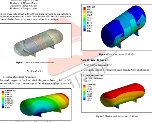
Diameter of RF pad= 572 mm Thickness of RF pad=12 mm Diameter of Flange=600 mm Thickness of Flange=12 mm
First to create solid model in Creo3.0 modeling software by using all above calculated parameters and ASME Code Section-VIII, Div-II. Three spaced sequential tube-sheets are mounted in vessel as shown in figure.
Figure -1 Solid model of pressure vessel
V. A
NALYSIS Modal Analysis Input Parameters:
One saddle support is fixed and check the contact between face to face contacts, edge to edge contacts, edge to face contacts are properly detected or not.
Figure -2Maximum deformation- 0.18 mm
Above results shows maximum deformat ion is 0.18 mm and Frequency is 2.7476 Hz, so frequency is more than zero shows the all the contacts are properly detected.
Static Structural Analysis Input Parameter:
1. Both saddle supports are fixed. 2. Gravity acting downward
Figure -3Maximum deformation-1.5616 mm
Figure -4 Maximum stress-65.87 MPa
Case-01: Input Parame ters
1. Apply Internal Pressure=0.32
2. One saddle support is fixed and on second saddle Apply displacement.
IJEDR1702109
International Journal of Engineering Development and Research (
www.ijedr.org
)
629
Figure -6 Maximum stress= 404.1 MPaCase 02: O ptimization of Tube-sheet at pressure 0.32 MPa Input Paramete rs
1. Fixed support
2. Apply pressure = 0.32 MPa
Sr. NO. Thickness
(mm)
Stress (MPa) Deformation
(mm)
1 409 38.48 17.441
2 400 40.54 17.045
3 350 53.35 16.898
4 280 84.71 16.175
5 240 116.75 16.648
6 230 127.56 16.5
Table :-2: Maximum Stress & Maximum Deformation results for Different Thickness of tube-sheet
Figure -7 Maximum deformation= 4.801 mm
Figure -8 Maximum deformation= 4.801 mm
T ube-sheet is analyzed for pressure of 0.32MPa, decreasing the tube-sheet thickness from 409 mm to obtained the optimum thickness. The stress at 230mm thickness of tube-sheet is 127.56 MPa which is nearest and less
than allowable stress. So the final Opt imum thickness for tube-sheet at
pressure of 0.32 MPa is decided at 230mm
.
Case 03: Tube-sheet Optimization with Point Load and pressure of 0.01MPa
Optimized 230 mm thickness of tube-sheet with applying Gravity, point mass 2.5 kg of every tube on mid-point of tube length and pressure on tube-sheet 0.01 MPa ,various analysis are as follows. No. T ube-Sheet = 1 Total number of T ubes = 1131 Mass of each tube = 2.5 kg Total mass of all tubes on the tube-sheet =2.5*1131 = 2827.5 kg
Figure -9 Deformation =7.7517 mm
Figure -10 Maximum stress= 66.195 MPa
Sr. NO. Thickness
(mm)
Stress (MPa) Deformation(
mm)
1 230 4.6618 0.1501
2 200 5.8856 0.2268
3 180 7.3474 0.3094
4 160 9.0768 0.4379
5 140 11.612 0.6495
6 120 15.671 1.0215
7 100 22.37 1.7403
8 80 34.559 3.322
9 60 66.195 7.751
Table -3: Maximum Stress & Maximum Deformation results for Different Thickness of tube-sheet with mass of each tube at its C.G.
IJEDR1702109
International Journal of Engineering Development and Research (
www.ijedr.org
)
630
Optimum thickness for tube-sheet with Point Load of each tube andPressure of 0.01MPa is decided at 60mm.
Case 04: Complete Vessel Analysis considering all tubes masses, pre ssure on tube -sheets 0.01MPa and inte rnal Pressure on all other components as 0.32 MPa
Total number of T ubes = 1131 Total number of tube sheets = 3 Mass of each tube = 2.5 kg Total mass of all tubes on the three tube sheets = 2.5*1131*3 = 8482.5 kg
Figure -11: showing Boundary Condition and all point masses on all tube-sheets
Figure -12: Deformation=21.52 mm
Figure -13: Stress=155.27 MPa
Case 05: Complete Vessel Analysis considering all tubes masses, pre ssure on tube -sheets 0.01MPa and inte rnal Pressure on all other components as 0.32 MPa with 3 saddle supports.
Figure -14: pressure vessel with 3 saddle supports
Figure -15: Deformation=21.072mm
Figure -16: Stress=122.08 MPa
Stress Result for Complete Vessel Analysis considering all tubes masses, pressure on tube-sheets 0.01MPa and internal Pressure on all other components as 0.32 MPa with3 saddle supports stress is 122.08MPa which is within the limit of allowable stress.
VI. C
ONCLUSIONIJEDR1702109
International Journal of Engineering Development and Research (
www.ijedr.org
)
631
2. The Analysis of pressure vessel model was done in ANSYS 15.0workbench. The results were supported with an experimental validation for verifying the actual deformation and FEA results. Following are concluding remarks based on the analysis performed on vessel.
3. Firstly analysis of pressure vessel model is done to develop the standard operating procedure. From the comparison of results at different mesh size.it is concluded that variation in results is within acceptable limit, hence approximately 100000 nodes mesh size is fixed for further analysis.in that maximum stress is 404.1MPa and deformation is 16.89 mm.
4. T ube-sheet optimization including point mass weight of 2.5 kg of each tube for reducing weight and material, 60 mm of tube-sheet is finalized.Optimizationresults shows 71% weight reduced of T ube-sheets.
5. Stress Result for Complete Vessel Analysis considering all tubes masses, pressure on tube-sheets 0.01MPa and internal Pressure on all other components as 0.32 MPa with 3 saddle supports is 122.08MPa which is within the limit of allowable stress (138MPa)
6. Experimental test shows that no leakage and damage in vessel.
Above all the conclusion shows the optimization of stress, weight and material is done. for this condition model is safe as per ASME Section-VIII, Div-II.
FEA results and Experimental results are in close resemblance and proved that FEA analysis is correct and is validated by experimental deformation results Manufactured tested values is 9.41mm. % error between FEA and experimental result’s is 17% which is less than the allowable error (20%) in FEA for large pressure vessel. Hence our FEA results are reliable. No damaged is detected by using ultrasonic testing machine. Finalized vessel satisfies ASME Criteria and this has been validated through FEA.
A
CKNOWLEDGMENTI am humbly expressing thanks to my respected guide Mr. Bhaumik B. Patel And my external guide Mr. Manan P. Panchal for their valuable time, constant help, encouragement and useful suggestions, which helped us in completing the research in time.
R
EFERANCES1. R. D. Patil, Dr. Bimlesh Kumar(2015) An Approach to Finite Element Analysis of Boiler T ube-Sheet. AJER e-ISSN: 2320-0847 p-ISSN: 2320-0936 Volume-02, Issue-08, pp-08-11.
2. Sui Rongjuan, W. W. (2014). Root cause analysis of stress corrosion at tube-to-tubesheet joints of a waste heat boiler. Engineering Failure Analysis 45, 398-405.
3. Ravivarma.R, A. P. (2014). Finite Element Analysis of a T ubesheet with considering effective geometry properties through design methodology validated by Experiment. International Journal of Computational Engineering Research (IJCER) ISSN (e): Vol, 04, Issue, 4, 2250-3005.
4. Shugen Xu, Weiqiang Wang (2013) Numerical investigation on weld residual stresses in tube to tube sheet joint of a heat exchanger. International Journal of Pressure Vessels and Piping 101, 37-44.
5. Shugen Xu, Y. Z. (2013). Using FEM to determine the thermo -mechanical stress in tube to tube–sheet joint for the SCC failure analysis. Engineering Failure Analysis 34, 24-34.
6. Dr. Enrique Gomez, D. E. (2013). ASME Section III Stress Analysis of a Heat Exchanger T ubesheet with a Misdrilled hole and irregular or thin ligaments. PVP 2013, 14-18.
7. Chi Bum Bahn, S. M. (2013). Leak behaviors of steam generator tube-to-tubesheet joints from room T emperature to 320 C. International Journal of Pressure Vessels and Piping 101, 45-54.
8. Chi Bum Bahn, S. M. (2013). Leak behavior of steam generator tube-to-tubesheet joints under creep condition:Experimental study. International Journal of Pressure Vessels and Piping 101, 55-63.
9. Kotcherla Sriharsha, V. R. (2012). Strength Analysis of T ube to T ube Sheet Joint inShell and T ube Heat Exchanger. International Journal of Science, Engineering and T echnology Research (IJSET R),Volume 1, Issue 4, 2278-7798.
10. H.F. Li a, C. Q. (2010). Cracking simulation of a tubesheet under different loadings. Theoretical and Applied Fracture Mechanics, 27-36.
11. Haifeng Wang, Z. S. (2007). Connection strength and tightness of hydraulically expanded tube-to-tubesheet joints. Journal of Materials Processing Technology 194, 93-99.
12. K. Behseta, S. S. (2006). On the design of the tubesheet and the tubesheet-to-shell junction of a fixed tubesheet heat exchanger. International Journal of Pressure Vessels and Piping 83, 714-720.
13. Weiya Jin, Zengliang Gao, (2004) Lihua Liang, Jinsong Zheng, Kangda Zhang. Comparison of two FEA models for calculating stresses in shell-and-tube heat exchanger. International Journal of Pressure Vessels and Piping 81,563–567.
14. V. G. Ukadgaonker, P. A., & Babu, S. (1996). Review of analysis of tube sheets. Int. J. Pre Ves. & Piping 67, 279-297.
15. ASME Boiler and Pressure Vessel Codes Section VIII, Division I.