INTRODUCTION
In the conditions of processing of metals pressure among the factors influencing plasticity as structure and structure of deformable metal, character of a tension at deformation, defor-mation speed, etc. is defordefor-mation temperature. Question of modeling of temperature fields, the describing temperature processes happening in the center of deformation and a technological stream of a camp were engaged many scientists. For creation of this algorithm the model [Du-binsky and Sosedkova 2007] was used. In work [Sosedkova et al. 2010] this model is realized by means of a method of final elements.
At the numerical solution of problems of distribution of a temperature field on cages of the closed rolling mill for the line of continu-ous molding and rolling of a metal rod one of
the most common method is the method of grids. Simplicity and universality are characteristic for difference methods for solving boundary value problems of mathematical physics in the regular settlement areas, and the use of irregular grids making closer the finite difference method with the finite element method. In work has been used economical the difference method for the solution of multidimensional equations in private deriva -tives [Samarskyi 1989], the method of total ap -proximation, which allows you to get absolutely stable converging locally – one-dimensional schemes for the equations of parabolic type.
RESEARCH OBJECTIVE
For numerical modeling of a temperature field on cages of the rolling mill we will con
-3D MODELLING OF DISTRIBUTION OF TEMPERATURE FIELD
IN THE ROLLING MILL
Yedilkhan Amirgaliyev1, Waldemar Wójcik2 , Tleugaisha Ospanova3, Kabilda Jetpisov3
1 Institute of Information and Computational Technologies, Almaty, Kazakhstan, e-mail: [email protected]
2 Lublin University of Technology, Nadbystrzycka 38d, 20-618 Lublin, Poland, e-mail: [email protected]
3 Eurasian National University named after L.N. Gumilyev, Astana, Kazakhstan, e-mail: [email protected], [email protected]
Volume 18, Issue 6, Nov. 2017, pages 1–7
DOI: 10.12911/22998993/76895 Research Article
ABSTRACT
This article is dedicated to the study of numerical simulation of temperature field distribution in rolling mill with many cages for continuous casting and rolling stripe of metal wire. In work the simplest is used in use, certainly a steady, economic difference method, a method of division of variables of a multidimensional task into a chain of one-dimensional tasks, a method of total approximation, the locally one-dimensional scheme. The algorithm of numerical modeling of distribution of a temperature field on cages of the rolling mill is constructed. Solutions of the three-dimensional temperature field distribution tasks based on experimental data allows finding the temperature across the strip of metal rod in a rolling mill stands. Cal-culation of the distribution of temperature field in hearth of deformation of a metal rod was realized on implicit scheme. The calculations are shown in the graphs. It provides an analysis of the error of errors.
Keywords: cage, hearth of deformation, rolling, temperature field, the locally one-dimensional scheme
sider a task for the heat conductivity equation in the form of [Sosedkova et al. 2010]:
𝑐𝑐𝑐𝑐𝜕𝜕𝜕𝜕𝜕𝜕𝜕𝜕 = 𝑑𝑑𝑑𝑑𝑑𝑑(𝜆𝜆 ∙ 𝑔𝑔𝑔𝑔𝑔𝑔𝑑𝑑𝜕𝜕) + 𝜏𝜏𝑠𝑠𝐻𝐻 (1)
where: c – specific heat of metal;
ρ – mass density of metal;
λ – thermal conductivity coefficient;
τs– resistance of metal of plastic defor -mation of shift;
H – intensity of speeds of deformation of shift, with the following boundary conditions:
At the entrance of the deformation center, the temperature of the metal known;
On a contact surface takes place the heat ex-change between deformable metal and a surface of rolls described by expression:
𝜆𝜆𝜕𝜕𝜕𝜕𝜕𝜕𝜕𝜕 = 𝛼𝛼𝑠𝑠(𝜕𝜕 − 𝜕𝜕𝑏𝑏) (2)
where: αs – heat transfer coefficient on a contact surface;
Ub – temperature of rolls.
On other surfaces, limiting the deformation center, the thermal stream is equal to zero.
At the exit from i– oh cages for practical cal-culations of temperature in multistand rolling mill we will use the simplified model [Dubinsky and Sosedkova 2007] which has an appearance:
𝑈𝑈𝑖𝑖 = 𝑈𝑈𝑖𝑖−1− ∆𝑈𝑈𝑢𝑢− ∆𝑈𝑈𝑘𝑘− ∆𝑈𝑈𝑏𝑏+ ∆𝑈𝑈𝑑𝑑 (3)
where: Ui – temperature at the exit from i – oh
cages,
Ui-1 – temperature at the exit from the pre -vious cage or temperature of initial heat -ing of preparation,
ΔUè – a heat transfer radiation in environ -ment which is described by Stephane-Boltsman’s formula,
ΔUk – a convective heat transfer,
ΔUb – contact heat exchange with work
-ing rolls,
ΔUd – a metal warming up due to energy
of plastic deformation.
According to the theory in the majority of pro -cessing of metal the form of preparation differs in pressure from the form of a finished product determined by a tool form. The closer the element is to a section corner, the he will receive smaller lengthening. Therefore the parties of section will
receive a convex form. Square section will come nearer to circular, and rectangular – at first to an ellipse, and then all the same to a circle. For ex-periment at a choice of a form of calibers of cages rectangular section was taken.
Difference equation
For drawing up algorithm of the numerical solution of the formulated task we will consider the three-dimensional parabolic equation of the second order in a general view [Samarskyi 1989]:
3
1
,
t x f U L t
U
,
U
x
k
x
t
x
U
L
,
,
x
,
t
c
10
,
c
1const
,
k
(4)
where: x = (x1, x2, x3) – point of 3-dimensional
space with coordinates
x1, x2, x3. Let G – any-dimensional 3 – area with border of Г, Ḡ = G + Г,
0
t
T
,
Q
G
0
t
T
.
G
Q
T
T
0
t
T
,
Q
G
0
t
T
.
G
Q
T
T
Is to find a continuous cylinder
Q
T solutionof the equation (4), meeting a regional condition
x
t
U
,
atxГ,0tT, (5)and the initial condition:
x
U
x
U
,
0
0 , atx
G
.
(6) As usual, it is supposed that this task has the only decision U = U(x,t), possessing all deriva -tives demanded on the statement course.We pass to writing of the local and one-di-mensional scheme now. We will construct a uni-form grid ωhr :
mk m m j j j t
h l N N i h i x
h
, ,
0
, ) (
3 ,
2
,1 , ,
,
0
,
When building a locally one-dimensional scheme formally replace the three-dimensional equation of one-dimensional chain of equa-tions, ie, approximate increments
3 τ
,
,1
2
,
3
3
1
L
U
f
t
U
U
(7)where
f
α meets a condition∑
f
=
f
=
3
1
α α .
For approximation
L
αU
+
f
α on a spatial grid ωh we will use the uniform differential operator ofthe second order of approximation
Λ
αy
+
ϕ
α.Boundary conditions and right part
ϕ
α undertakein any time points:
, 0.5
, 3
, /3
, ,12,3.3
j f xtj j xtj
Approximating each heat equation numbers α on the interval tj+(α-1) / 3 < t ≤ t j+a / 3 a
two-layer scheme with weights, we obtain a chain p dimensional scheme which called locally one-dimensional scheme: h j j j j j x U U U U , 3 , 2 ,1 ,
1 3 3
1 3 3 1 3 (8)
where: σ – arbitrary number
Consider a purely implicit locally one-dimen -sional scheme, at σ = 1:
h j j j j x y y y , 3 , 2 ,1 , 3 3 3 1 3 (9)
The boundary condition:
3 3 j j
y at xh,,
3
,
2
,1
,
...,
,1
,
0
0
j
j
(10)The initial condition:
x u
xy ,0 0 (11)
Let us more detail on (9):
1 3 1 3 3 2 1 3 2 2 3 2 2 3 1 3 2 3 1 1 3 1 1 3 1 j j j j j j j j j j j j f y y y f y y y f y y y , j ,1m1 (12)
The boundary condition:
3 , 2 ,1 , , , , 3 3 0 3 0 3 l x j l x j x j x j t x y t x y (13)
The initial condition:
)
(
0
0
U
x
y
=
(14)Let us consider each of the three separate equations (12). First of the equation (12) write at the form:
j j j j j i j i j i j i j i j i j i j i f y h y k y k k y k y 1 3 1 1 2 1 1 1 1 1 1 1 1 1 1 1 1 1 1 1 1 1 1 1 1
11 1 1 1 1 1 1 1 ,
(15)
where: j = 0,m –1 ,
i1 = 1,n1 –1 ,
i2 = 0,n2 ,
i3 = 0,n3 ,
m j t
x f
f1j , j 2, ,1
(15) rewrite at the form:
j j i j i j i j i j i j i j i y k h y k h y k k h 1 1 1 1 1 1 2 1 1 1 1 1 1 1 2 1 1 1 1 1 1 1 1 2 1 1 1 1 1 1 1 1 1 (16) Denoting:
ji i i i j i
i h k C A A F
A 1 1 1
1
2
1 1 1 1 1 1
1 , 1 ,
get:
1 ,1 ,1 ,1 ,1 ,1 , 3 3 2 2 1 1 1 1 1 1 1 1 1 11 1 1 1 1 1 1
1 n i n i n i F y A y С y
Ai ij i ij i ij i
(17)
Boundary conditions generally:
112 1 1 1 2 1 1 1 11 1 1 1 1 1 0 1 1 1
,
j j n j n j j jy
y
y
y
(18)where: χ1 = 0, χ2 = 0 – First type boundary con
-ditions, j y j1 Ui
21 0
1
11 ,
, whereUi – the temperature outlet i – in (3).
Next, substituting known y0 values are calcu
1
,1
,1
,1
,
0
,1
,
,
1
,
,
,
,
3 3 2 2 1 1 1 1 1 1 1 1 1 2 2 1 12 1 1 0 11 1 1 1 1 1 1 1 1 1 1 1 1 1 1 1 1 1 1 1 1 1 1 1 1 1 1
n
i
n
i
n
i
y
y
y
A
C
F
A
A
C
A
i j i i j i n n j j n i i i i i i i i i i i i
(19)The second of the equation (12) is written in the form:
j j
j j j i j i j i j i j i j i j i j i f y h y k y k k y k y 2 1 1 2 2 2 2 1 1 2 1 2 1 2 1 2 1 1 2 1 1 2 1 1 2 1
21 2 2 2 2 2 2 2 ,
(20)
where: j = 0,m –1 ,
i1 = 1,n1 –1 ,
i2 = 0,n2 ,
i3 = 0,n3 ,
m j t
x f
f2j , j 2, ,1
(20) rewrite at the form:
j ji j i j i j i j i j i j i
y
k
h
y
k
h
y
k
k
h
2 1 1 2 1 2 2 2 1 1 2 1 1 2 2 2 1 2 1 2 1 1 2 2 2 2 2 2 2 2 2 21
(21) Denoting,( )
(
)
ji i i i
j
i h k C A A F
A 1 1 2
2 2
2 2 2 2 2 2
2 , 1 , ϕ
τ = + + = = + + get:
1 ,1 ,1 ,1 ,1 ,1 , 3 3 2 2 1 1 1 1 2 1 1 2 1 1 2 2 2 2 2 2 2 2 n i n i n i F y A y С y A i j i i j i i j i i (22)Boundary conditions generally:
122 1 1 2 2 1 2 1 21 1 1 2 1 1 0 2
,
j j n j n j j jy
y
y
y
(23) where:(
2)
2(
2)
1
=
λ
/
λ
+
α
β⋅
h
,
χ
=
λ
/
λ
+
α
β⋅
h
χ
– third type boundary conditions.
Next, substituting known values
y
1j+1 areF2 calculated, and then sweep method solve the problem (22) in all the nodes of the grid ωh. The third of the equation (14) is written in the form:
j j j j j i j i j i j i j i j i j i j i f y h y k y k k y k y 3 1 2 3 3 2 3 1 1 3 1 3 1 3 1 3 1 1 3 1 1 3 1 1 3 1
3 3 3 3 3 3 3 3 3 ,
(24)
where: j = 0,m –1 ,
i1 = 1,n1 –1 ,
i2 = 0,n2 ,
i3 = 0,n3 ,
m j t
x f
f j j , ,1
2
,
1
(24) rewrite at the form:
j ji j i j i j i j i j i j i
y
k
h
y
k
h
y
k
k
h
3 1 1 3 1 3 2 3 1 1 3 1 1 3 2 3 1 3 1 3 1 1 3 2 3 3 3 3 3 3 3 3*
*
*
*
*
*
1
(25) Denoting,( )
(
)
ji i i i j i
i h k C A A F
A 2 3 1 1 3
3 3 3 3 3 3
3 , 1 , ϕ
τ = + + = = + + get:
1 ,1 ,1 ,1 ,1 ,1 , 3 3 2 2 1 1 1 1 3 1 1 3 1 1 3 3 3 3 3 3 3 3 n i n i n i F y A y С y A i j i i j i i j i i (26)Boundary conditions generally:
1 32 1 1 3 2 1 3 1 31 1 1 3 1 1 0 3 3 3 , j j n j n j j j y y y y (27)where:
3
2 3 1 / , / h h
Third type boundary conditions.
Next, substituting known values
y
1j+1 areThe solution is
( )
3 1 3+
j i
y
.The results of numerical calculations
In order to test the proposed algorithm is numerically solved the problem (4) in the par -allelepiped and the relative errors were ob -tained by calculations in the corresponding norm [Ryndin 2003]:
0 0
1
..., ,
2
,1 , 11 ,1
, max
max
j j
i
y y yj j ij
where: j – iteration number,
i – number of stands.
The results of calculations of the relative error εij shown in Figure 1. When the imple-mentation of the computing process each suc-cessive approximation to the solution or rather the previous one, ie, error εij decreases with each iteration. So iterative process converges.
The developed algorithm for solving the problem of temperature conditions allows for temperature changes directly into the rolling stand and the interstand gaps in the rolling mill. The algorithm can be used to calculate the temperature distribution of various rolled materials on any type of profiled rolling mill.
The program implements the algorithm for solving the temperature field distribution of the metal rod on a rolling mill stand is written in Fortran PoverStation 4.0. For the calcula -tion as input data from the literature were used. As a result of the calculation were obtained: three-dimensional temperature field. The re-sults of studies of the temperature field of the metal rod from alloy VT6.
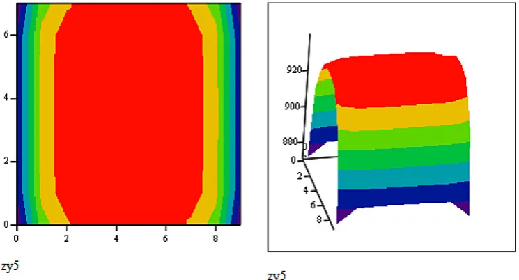
Initially heated to a temperature of 950 °C the preform is fed into a first roughing mill, af -ter rolling in the stand surface of the strip is cooled to a temperature in the range 904–949 °C. Figure 2 shows a cross-section of roll after the fifth stand, where the surface temperature of roll in contact with the roller, due to heat trans-fer is reduced to 880 °C, resulting in a greater plastic deformation angle bars and more strain warming seen smaller drop in temperature – up Fig. 1. The results of calculating the relative error
to 915 °C. Sides contacting only with the envi -ronment, are cooled to a temperature of 938 °C. Theoretically, we assume that, after five pas -sages in the cage strip is cut to length, cooled, and then reheated to a temperature of 950 °C. Further, it was rolled in the group stands for 6 passages, i.e. 6 to 11 cages. The results of the cross-section of roll cage after 11 passages are shown in Figure 3.
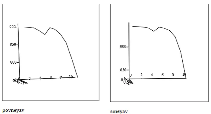
According to the theory of metal forming to obtain the desired homogeneous structure neces-sary to achieve a uniform temperature over the cross section of the rod. As seen in Figure 3, this condition is satisfied, although I realize this con -dition is almost impossible. The resulting calcula-tion of the implicit local-dimensional pattern of roll temperature of different parts of the passage shown in Figure 4.
Studies show that the structure of the center and surface of the rod characterized by, caused by the temperature difference of about 50 °C and heating the strip, the condition of up to 950 °C at the inlet of first and second stand, i.e. temperature curve accurately describe the process of deforma -tion of the metal rod.
CONCLUSION
Designed algorithm for the numerical simulation of the temperature problem pro-vides a three-dimensional model of the tem -perature field bands in the deformation in multistand mill, as well as conduct experi-ments by changing these or other factors af -Fig. 3. The cross-section of roll cage after the eleventh passages
fecting the strength and ductility of a deform -able metal, including the shape of the cali-bration without the need for costly full-scale experiments.Checking the accuracy of the calculation and comparative analysis of tem -perature fields rolling enables the use of the algorithm locally one-dimensional schemes in the profiled rolling.
Acknowledgements
This research was financially supported by the National Science Foundation in Kazakhstan.
REFERENCES
1. Dubinsky F.S., Sosedkova М.А., 2007. Methods of
designing temperature regimes of hot bar rolling: A tutorial textbook. Chelyabinsk: Pub. SUSU, 18 p. 2. Ryndin E.A. 2003. Methods for solving problems
of mathematical physics. Textbook. Taganro: Pub-lishing – TRTU, 119 p.
3. Samarskyi А.А. 1989. The theory of difference
schemes. Third ed., Moscow.
4. Sosedkova М.А., Dubinsky F.S., Dukmasov V.G.,