151 IJSTR©2012
www.ijstr.org
Powertrain Warm-up Improvement using Thermal
Management Systems
Waleed Nessim, Fujun Zhang
Abstract— Adjusting operating temperature of the engine in the steady state and during warm-up improves fuel consumption and reduces engine emission through higher operating temperatures. Also it can improve thermal comfort by faster cabin heater performance. Thermal fluid analysis by 1-D simulation is an effective tool for studying the control of the entire cooling system and optimization of engine performance by using active control thermal management systems which allow high tolerance for coolant temperature across speed-load map of the engine. In this work a 1-D simulation model (GT-SUITE) was used to evaluate the effect of warm-up improvement on powertrain performance by using electric coolant pumps and fans, electronic control valve, and an electronic control system with PID feedback. Firstly, the cooling system model was validated with experimental data, and then replaced with an advanced thermal management sys tem. The effect of fan speed and pump speed on engine coolant temperature with different thermal management strategy during warm up was studied. Depending on the operating conditions, the results showed an improvement in brake specific fuel consumption (3-9%) and stability improvement in outlet coolant temperature due to controller tuning during steady state operation.
Index Terms— Cooling System, Detailed Model, Fuel Economy, GT-SUITE, PID Controller, Thermal Management System, Warm-up.
————————————————————
1.Introduction
Although modern engines have been developed in almost areas, Today’s coolant system consists mainly of components and technologies that have unchanged for long time, it involves a mechanical thermostat in conjunction with an engine driven water pump and fan. Thermostats are mechanical valves that use melting wax, which expands and moves the valve opening over a prescribed temperature band. Engine driven water pumps and fans are directly linked to the engine rpm and thus produce flow rates based on that rpm. These types of thermal controls are generally not very accurate, not controllable and lead to considerable parasitic losses [1]. Conventional engine cooling systems are designed to just guarantee a sufficient heat removal at maximum engine output conditions at the worst vehicle operating conditions (low vehicle speed and high ambient temperature) However, these operational conditions only represent approximately 5% of the conditions that the vehicle will encounter during its life [2]. This approach results in poor fuel economy that could be enhanced with thermal management systems. Three-dimensional computational fluid dynamics (CFD) tools are commonly used for studying the flow of fluid inside engines. While they enable detailed analyses, the analysis range and conditions are limited due to the modeling and calculation time. On the other hand, while one-dimensional thermal fluid analysis does not provide detailed fluid flow analysis inside a water jacket, it enables the entire cooling system control to be studied and the piping to be optimized.
It also facilitates transitional calculations of the mode drive, which are difficult with three-dimensional analysis [3]. In this work one-dimensional thermal fluid analysis software “GT-SUITE” was used to simulate the conventional cooling system then after validation, the cooling system was modified with an active electric control one. The objective of this work is to conduct simulation studies to evaluate the impact of the controllable electric cooling system on the cooling performance and its effect on the fuel economy for different operating conditions and make maps for the engine operating conditions.
2 T
HERMALM
ANAGEMENTS
YSTEMSB
ENEFITSIdeally, engine cooling is undesirable from the thermodynamic point of view. If the heat transfer rates from the gas to metal could be reduced, then more power could be produced at a particular fuel flow rate, i.e. the thermal efficiency of the engine would increase. Also the heat removed out via radiator could be reduced and hence smaller radiator size. However, in practice, the engine metals can withstand only a certain maximum temperature level. Engine oil also loses its lubricating qualities when temperatures exceed 177°C and, as a result, excessive engine wear occurs [4]. That is why powertrain thermal management is extremely necessary for good engine reliability and durability with a compromise of the thermal efficiency. The key benefits of thermal management systems can be summarized as follow:
1) Reduce parasitic power losses. 2) Decrease exhaust emissions.
3) Improve flexibility in component packaging. 4) Enhance fuel economy.
5) Improve cooling system control.
6) Quicker engine warm-up during cold start. 7) Reduce engine wear and friction.
8) Increase lubricant life.
9) Eliminating overcooling during part load operation. 10) Reduce system pressure drop and hose lose. 11) Eliminating hot soak after engine stop. 12) Increase average combustion temperature. ————————————————
Waleed Nessim is currently pursuing Ph.D. degree program in School of Mechanical Engineering in Beijing Institute of Technology, China, PH-+8615201318676.
E-mail: [email protected]
Fujun Zhang is professor of Laboratory of Vehicle Power-train System School of Mechanical Engineering, Beijing Institute of Technology, China ,PH-+8613911254765.
152
3 E
NGINET
HERMALB
ALANCEE
XPERIMENTEngine thermal loads are created through the conversion of chemical energy to thermal and mechanical energy and the transfer of that energy through the powertrain. Typical Engine has three areas where combustion energy is dispersed. About 40% goes to produce the effective power, 30% leaves through the exhaust and 30% leaves through the coolant system. Engine heat rejection via cooling system was calculated via special test rig as shown in Fig.1.
The heat rejection from the engine to coolant was calculated at different operation conditions by using the following equation:
𝑄𝑐= 𝑚 𝑐𝐶𝑝(𝑇2− 𝑇1) (1)
𝑚
𝑐= 𝜌
𝑐∀
(2)Where:
Heat rejection to coolant (kJ/s) Coolant mass flow rate (kg/s)
Specific heat capacity of the coolant (kJ/kg.K) Temperature at engine inlet (K)
Temperature at engine outlet (K) Coolant density (kg/m3)
Coolant volume flow rate (m3/sec)
4 S
YSTEMM
ODELINGTCD 6V2015 diesel engine with its cooling system was used to configure the cooling system model by using one dimensional simulation program GT-Suite (GT-COOL, GT-POWER) program.
4.1. Engine Model
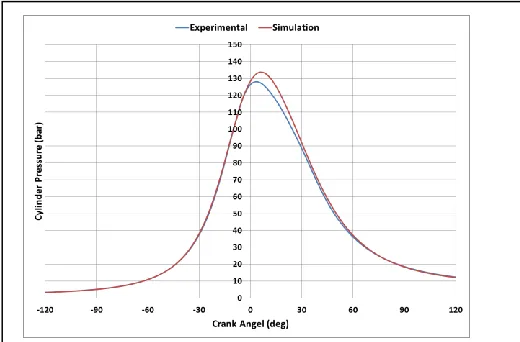
GT-POWER uses one dimensional gas dynamics to represent the flow and heat transfer in the components of the engine model [5]. The engine has been modeled with GT-POWER and validated using the experimental data of engine performance which has conducted in “Power Mechanism and Engineering Laboratory, BIT”. The main engine data are listed in table 1.
Fig. 2 shows a comparison of the measured and predicted cylinder pressure with crank angel.
The GT-POWER engine model was used to obtain Fuel map, Heat rejection map and Friction map.
4.2 Cooling Model
GT-Cool is based on one-dimensional fluid dynamics, representing the flow and heat transfer in the pipe and the other components of a cooling system [5]. It is a module-based code that provides flexible model building capability. The specifications of engine cooling system are listed in table 2. Fig. 3 shows a comparison of the measured and predicted engine heat rejection. Fuel map, Heat rejection map and Friction map which obtained from GT-POWER were used in order to simulate engine cooling system. These results indicate that this cooling system model is capable of simulating cooling system behavior during steady and transient engine condition and evaluating the cooling system performance.
TABLE1 ENGINE MAIN DATA
Fig. 1. Engine cooling experiment. In this test rig, the original radiator in the vehicle is emulated by an intensive heat exchanger which is cooled by the outside cold water. The temperature and pressure of coolant entering and leaving the engine were measured by setting two temperature and pressure sensors; also a flow sensor was fixed after the heat exchanger to measure the coolant flow rate.
153 IJSTR©2012
www.ijstr.org
TABLE2COOLING SYSTEM SPECIFICATIONS
4.3 Integrated Engine and Cooling System Model
The engine and the thermal management system that encompasses it have inherent interactions. These interactions have a pronounced effect on both systems. For this reason, an integrated model for the engine and its conventional cooling system was established with GT-SUITE program using the data from the manual to model the behavior of the entire assembly accurately and evaluate the cooling system performance and its effect on the engine. In general, this involves the application of boundary conditions at several interfaces between the engine and thermal management system. The model is capable of simulating cooling system
behavior at different operating conditions and its effect on engine performance. Fig.(4) shows the traditional TCD 6V2015 diesel engine cooling system in a simplified schematic.
5.A
DVANCEDT
HERMALM
ANAGEMENTM
ODELConventional cooling system has been replaced with an advanced thermal management system using GT-SUITE simulation program. The model consists of four circuits, the gas circuit, oil circuit, coolant circuit and the air circuit. As shown in Fig. (5), the connections between the engine and the cooling system must be made at the interfaces between engine and the thermal management system. Different operating scenarios were used to study and evaluate its performance over a wide range of engine operating conditions. RPM and load were varied over the simulation cases to determine the ability of cooling system to reject the engine heat at different operating conditions and determine effect of replacing the mechanical pump, fan and thermostat with electric ones, also the effect of controlled system on warm up period and the specific fuel consumption at different coolant temperatures were evaluated. A control loop feedback mechanism was applied to the controlled system by using Proportional, Integral, Derivative (PID) controllers to control Fig. 3. Cooling model validation at part load. The results
produced by simulation are matched closely with measurements with less than 1.56% error.
Coolant volume in engine (ltrs) 17
Coolant volume in radiator (ltrs) 20
Expansion volume in expansion tank (Ltrs) 3
Volume of expansion tank (Ltrs) 6
Temperature of thermostat begin to open (o
C) 83
Maximum heating up of coolant by engine (o
C) 9
Coolant density kg/m3
1005
Coolant specific heat (kJ/kgo
C) 3.53
Coolant volume flow rate at 2100 rpm (Ltr/min) 375
Diameter of pipes on radiator (mm) 70
Diameter of expansion tank compensation pipes (mm) 20
Minimum pressure in expansion tank compensation pipe (bar) 0.3
Total radiator volume (ltr.) 444
Temperature at full load and rated speed (o
C) 95
Maximum coolant temperature at engine outlet (o
C) 103
Ambient temperature [inlet air to HX] (o
C) 40
Maximum ambient temperature for air side (o
C) 42
Diameter of venting pipes (mm) 8
Radiator core Area (m2
) 0.8
Core depth (mm) 70
Coolant volume flow rate for cabin heater at 2100 rpm (ltr/min) 40
Diamter of cab heating (mm) 16
Engine structural volume [Block+Head] (ltr) 200
Engine structural surface area [Block+Head] (m2
) 2.5
Fig. 4. A simplified schematic for the cooling system
1. Cab heating
2. Coolant pump
3. Lubricating oil cooler Coolant duct 4. Engine
5. Gear oil cooler 6. Temperature sensor 7. Thermostat
8. Compensation tank 9. Heat exchanger 10. Fan
154 the lift of the electric thermostat and speed of the pump and
fan.
6 R
ESULTS AND ANALYSISA number of scenarios have been used to evaluate the electronic control cooling system. During the warm up period, the electric valve was used to stop the bypass flow at the same time the electric pump was used to flow the coolant to cabin heater only. By this way the cabin heating has been improved and also the warm up period has been decreased about 50%. Fig. (6) illustrates the temperature of the coolant exit from the engine at cold start (rpm = 1000 ).
It compares between the conventional cooling system and the electric control one which use electric pump, electric fan, and electric valve. As shown in this figure, the conventional thermostat does not give precise control needed for the cooling systems because the wax thermostat has slow response and unnecessary temperature fluctuation and lack of accuracy. It is a single point controllers only activated at a certain coolant temperature. The electric valve was used to raise the coolant temperature higher than with a conventional thermostat to improve the cold start and warm up process. In this manner the engine can run warmer than normal which can enhance combustion along the walls, improve heat flow and obtain higher combustion temperatures which enhance engine performance and reduce the fuel consumption.
Fig. (7) shows the ability of the electric control system to reject that heat even at severe condition (high load and low RPM).
It can be notice that the outlet temperature from the engine is lower than the conventional system which means that the heat exchanger heat transfer surface area can be reduced and the system can be downsized and still satisfy the temperature limit established for the conventional system. The electric control cooling system can satisfy the engine needs at high thermal load situations with lower pump and fan flow rate due to the active control of the coolant flow regardless the engine speed which leads to increase cylinder head, cylinder liner and oil temperature and engine thermal efficiency. These features will make the engine runs more efficient, reduce wear and the oil life can be extended and decrease the specific fuel consumption.
Fig. (8) shows the specific fuel consumption (SPC) at 1000 rpm and 2100 rpm and at different loads, from this figure we can note that the specific fuel consumption decreases especially at part load where the heat rejection from the engine at these conditions is reduced and no need to operate the mechanical pump or fan with its full capacity.
Fig. 5. Advanced detailed cooling system model
1. Gas Circuit (Engine) 2. Oil Circuit
3. Cylinder Block 4. Cylinder Head 5. Pump Control 6. Air Circuit 7. Fan Control
Fig. 6. Engine Temperature (Exit)
Fig. 7. Engine Coolant Temperature.
200 220 240 260 280 300
25 50 75 100
SF C ( g/ kW h )
Load (%)
1000 rpm conventional Cooling System 1000 rpm Electric Control Cooling System
2100 Conventional Cooling System 2100 rpm Electric Control Cooling System
155 IJSTR©2012
www.ijstr.org
Fig. (9) and Fig. (10) show the effect of control cooling system on the specific fuel consumption SFC. The electrical controlled system can improve the SFC (3:9 %) especially during warm up period or at high rpm due to the control of pump and fan speed and flow rate.
7
C
ONCLUSIONThe detailed cooling system model for TCD 6V2015 diesel engine was configured with commercial code, GT-SUITE. The simulation results were compared with experimental data in order to validate the conventional cooling system model then a controlled cooling system model was conducted to study its effect on the fuel economy under different operating conditions. The computer controlled cooling system met the objectives of increasing engine, cab heater, and coolant temperatures to the optimum working temperatures which led to energy saving during vehicle warm-up period. The main conclusions of this research are summarized as follows:
1) Reducing the parasitic losses for pump and fan. 2) Controlling the pump speed and fan speed to
increase the engine thermal efficiency.
3) Using electric thermostat to reduce the pressure resistance and increase its response.
In addition, the use of this detailed model will enable the investigation of more innovative control systems for both existing and proposed hardware, even using
Hardware-in-the-Loop (HIL) simulations to prove new ideas.
A
CKNOWLEDGMENTThe authors would like to thank Laboratory of Vehicle Power-train System team, Beijing Institute of Technology for their support and encouragement to publish this paper.
R
EFERENCES[1] Hnatczuk, W., Lasecki, M.P., Bishop, J., Goodell, J., “Parasitic Loss Reduction for 21st Century Trucks,” SAE Paper 2000-01-3423, 2000.
[2] Chad Lehner, Gordon Parker, Oner Arici and John Johnson, “Design and Development of a Model Based Feedback Controlled Cooling System for Heavy Duty Diesel Truck Applications using a Vehicle Engine CoolingSystem Simulation, ” SAE Paper, 2001-01-0336, 2006.
[3] Filip Kitanoski,Wolfgang Puntigam, Martin Kozek, Josef Hanger., “An Engine Heat Transfer Model for Comprehensive Thermal Simulations,” SAE Paper, 2006-01-0882, 2006. [4] Oner Arici, John H. Johnson and Ajey J. Kulkarni, “The Vehicle
Engine Cooling System Simulation, ” SAE Paper, 1999-01-0240, 1999.
[5] GT-SUITE manual, Gamma Technologies, 2009. Fig. 9. Engine Coolant Temperature.