Analysis of Bubble Deck Slab Design by Finite
Element Method
Mrinank Pandey Manjesh Srivastava
Department of Civil Engineering Department of Civil Engineering Madan Mohan Malaviya University of Technology,
Gorakhpur
Madan Mohan Malaviya University of Technology, Gorakhpur
Abstract
Engineering use a wide range of tools and techniques to ensure that the design they create are safe. However accidents sometimes happen and when they do, companies need to know if a product failed because the design was inadequate or if there is another cause, such as a user error. But they have to ensure that the product works well under a wide range of condition, and try to avoid to the maximum a failure produced by any cause. One important tool to achieve this is the finite element method.
Keywords: Bubble Deck Slab, Bridge Deck Slab, Finite Element Method
________________________________________________________________________________________________________
I. INTRODUCTION
The finite element method is one of the most powerful numerical techniques ever devised for solving differential (and integral) equation of initial and boundary-value problem in geometrically complicated region” (Reddy,1988).There is some data that cannot be ignored when analyzing an element by the finite element method. This input data is to define the domain, the boundary and initial condition and also the physical properties. After knowing this data, if the analysis is done carefully, it will give the satisfactory result. It can be said that the process to do this analysis is very methodical and that it is why is so popular, because that makes it easier to apply. “The finite element analysis of a problem is so systematic that it can be divided into a set of logical steps that can be implemented on a digital computer and can be utilized to solve a wide range of problems by merely changing the data input to the computer program (Reddy 1988)
The finite element analysis can be done for one, two and three-dimensional problems. But generally, the easier problems are those including one and two dimensions, and those can be solved without the aid of computer, because even if they give a lot of equation, if they are handled with care, an exact result can be achieved. But if the analysis requires three-dimensional tools, then it would be a lot more complicated, because it will involve a lot of equation that are very difficult to solve without having an errors. That is why engineers have developed software that can perform these analyses by computer, making everything easier. This software can make analysis of one, two and three dimensional problems with a very good accuracy.
A basic thing to understand how finite element works is to know that it divides the whole element into a finite number of small elements. "The domain of the problem is viewed as a collection of nonintersecting simple sub domains, called finite element. The subdivision of a domain into elements is termed finite element discretization. The collection of the elements is called the finite element mesh of the domain." (Reddy, 1988). The advantage of dividing a big element into small ones is that it allows that every small element has a simpler shape, which leads to a good approximation for the analysis. Another advantage is that at every node (the intersection of the boundaries) arises an interplant polynomial, which allows an accurate result at a specific point. Before the finite element method, engineers and physicians used a method that involved the use of differential equations, which is known as the finite difference method.
II. PRELIMINARIES
In this section, we describe the design principle based on doctrine of capacity design, push over analysis and the shear strength of coupling beam in brief:
The Purpose of FEA
Analytical Solution
1) Stress analysis for trusses, beams, and other simple structures are carried out based on dramatic simplification and idealization.
2) Mass concentrated at the center of gravity
3) Beam simplified as a line segment (same cross-section)
4) Design is based on the calculation results of the idealized structure & a large safety factor (1.5-3) given by experience FEA
2) To understand the physical behaviors of a complex object (strength, heat transfer capability, fluid flow, etc.)
3) To predict the performance and behavior of the design to calculate the safety margin; and to identify the weakness of the design accurately
4) To identify the optimal design with confidence
In my thesis work the use of finite element method use for the analysis of the bubble deck slab in which we analysis the shear force and deflection and for the moving load as well as the strength and compare with the same parameter for the conventional deck slab system. With the help of the finite element analysis software. The finite element method (FEM), or finite element analysis (FEA), is a computational technique used to obtain approximate solutions of boundary value problems in engineering .Boundary value problems are also called field problems. The field is the domain of interest and most often represents a physical structure.
Bridge Deck Model
The bridge deck model was designed and analysis by the software in finite element analysis in the static analysis and the dynamic analysis of the solid slab as well as the bubble deck slab. In order to fully understand the previous research conducted on the bubble deck, further analysis was performed to compare the response of this new type of slab and conventional solid slab. A 3D solid slab and bubble deck slab were constructed in the ANYSIS 2000 with the entire dimension as in use in the laboratory. Each solid slab finite element model has approximately 8,100 elements. A 3D rendering of the solid slab with the column supports is displayed in figure 1. The solid slab was generated as a thick shell of pure concrete while the Bubble deck slab was designed as a layered shell. For simplicity in the Bubble deck model, a rectangular layer of HDPE was sandwiched in between two layers of standard concrete on top and bottom (see in figure 1) for the simplified Bubble deck slab layers as used in the analysis. Both model were subjected to a 100 KN load in addition to their own self weight for the static and dynamic design. (See in figure 2) and the cross section and isometric view of bubble deck slab are shown in the figure 1.and all the dimension of the bubble deck slab are given in the table.
Fig. 1: 3D rendering of the solid slab with the column supports [2]
Fig. 2: the cross section and isometric view of bubble deck slab [2]
The material properties used are typical for standard concrete and HDPE in the India. See figure for the single module in AYSIS 2000, Table 1 for module dimension and the table 2 for the property used in the models.
Table – 1
Dimension of Bubble deck slab Dimension of bubble deck slab
Bubble diameter 6.50cm
Depth 14cm
Width 30cm
Table – 2 Material Property
Material Compressive strength (kN/m2) Young Modulus (kN/m2)
Poisson’s Ratio
(kN/m2) Thermal Expansion
Density (kN/m2)
Concrete 25,000 2.48E+07 0.16 5.5E-6 25
HDPE 30,000 8.00E+05 0.42 2.0E-5 10.01
The ANYSIS 2000 models of bubble deck slab consist the approximately 7500 element.
III. METHODOLOGY
Static Method
Static analysis calculates the effect of steady loading condition on a structure, while loading conditions on a structure, while ignoring inertia and damping effects, such as those caused by Time- Varying loads. A static analysis can, however, include steady Inertia loads (such as gravity and rotational velocity), and time – varying loads that can be approximated as static equivalent load (such as the equivalent wind and seismic loads commonly defined in many building codes).
Static method determine the displacements, stresses, strain and forces in structure or components caused by load that do not induce significant inertia and damping effects. Steady loading and response conditions are assumed; that is the load and the structure’s response are assumed to vary slowly with respects to time. The types of loading that can be applied in static analysis include:
Externally applied forces and pressure
Steady –state inertial force (such as gravity or rotational velocity) Imposed displacements
Temperature (for thermal strain)
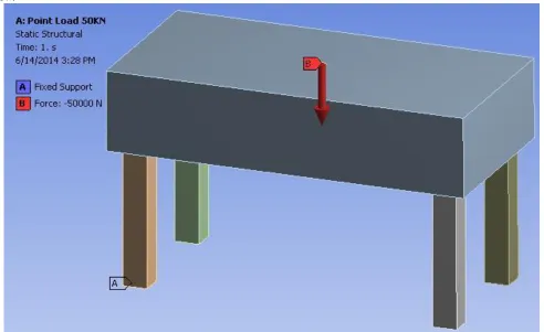
In my thesis work the type of loading that can be applied in bubble deck slab and the conventional deck slab is externally applied force in different types. Like point load (50kn).in both the slab which is simply supported which are designed in the ANYSIS and compare the maximum stress and maximum deformation in both the slab. Which are given below Figure 3 shows the model of conventional solid deck.
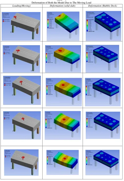
A moving load of 100kN was applied on the bubble deck slab as well as solid deck slab. A comparison study was made on both the slabs for maximum stress and maximum deformation. The maximum deformation is shown in the Table 3 which is given below.
Table – 3
Deformation of Both the Model Due to The Moving Load
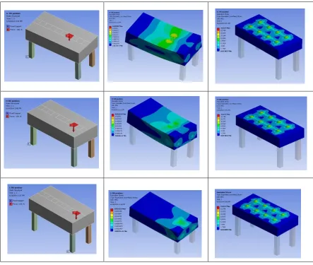
The maximum stress of both the model are shown in the table which are given below Table – 4
Stress of Both the Model Due to The Moving Load
IV. ANALYSIS AND RESULTS
The maximum internal stresses and forces in the bubble deck model exceeded those of the solid slab. The maximum moment and internal stress of the Bubble deck was 64% higher than the solid deck for further study on bubble deck slab and solid deck slab analysis was done on the solid slab and bubble deck slab in ANYSIS2000. Both the slabs where model in Anysis2000 according to the experimental model parameters and the slabs were analyzed for the static response under the different loading parameters. The shear force developed in x z direction(V13), in y z direction (V23), the maximum stresses that are developed in the deck(Smax),and the deflection U(3) .Table summarize the static response result from the test of bubble deck slab in ANYSIS200.
Table – 5
Stress and Forces Developed in Bubble Deck and Solid Deck
The ANYSIS2000 result shows that the maximum moments, shear force and in-plan stress in the bubble deck is 10-25% less than that of solid concrete slab under the same conditions. This is a consequence of the decreased dead load from the HDPE spheres in place of concrete. Additionally, this load reduction for the permanent condition lowers the overall stress and is therefore beneficial for the long term response of the deck system.
V. CONCLUSIONS
1) The market of construction in bridge deck slab as well as the building industry consists mainly of massive concrete floors, prefabricated filigree slab floors and hollow core slab floors. This situation has not changed for more than 20 years. But this innovative slab construction technology is proven to be more efficient than a traditional biaxial concrete deck slab in an bridge deck system. The finite elements models of the office slabs created for this study in ANYSIS2000 verify the prior analysis and experiments.
V13 V23 Smax U
Solid deck -340.047 -339.469 95.779 2.8382
Bubble deck 305.896 305.434 83.289 3.5017
2) Deflection of bubble deck is 18% more than the solid slab as the stiffness is reduced due to the hollow portion. 3) Weight reduction is 15% compared to solid slab.
4) This innovative slab system with considerable reduction in self-weight and savings in materials combines all advantages of the other slab system, solving all problems caused by their disadvantages in the same time. Besides the new slab deck system enhances the structural possibilities in combination with an improved cost-effectiveness. Further on the slab deck system gives a tremendous contribution to sustainable development
ACKNOWLEDGMENT
This work has been carried out in civil engineering department of Madan Mohan Malaviya University of Technology, Gorakhpur, India. The authors present its heartiest gratitude towards the entire faculty members for their constant encouragements, guidance and supports.
REFERENCES
[1] Wang, K., Jansen, D.C., and Shah, S., "Permeability study of cracked concrete," Cement and Concrete Research, Vol.27, No.3, 1997, pp. 381-393. [2] Sergiu Cal in, Ciprian Asavoaie and N. Florea, "Issues for achieving an experimental model" Bul. Inst. Polit. lai, t. LV (LIX), f. 3, 2009.
[3] Martina Schnellen bach-Held and Karsten Pfeffer,"Punching behavior of biaxial hollow slabs" Cement and Concrete Composites, Volume 24,Issue 6, Pages 551-556, December 2002
[4] Sergiu Calin and Ciprian Asavoaie, "Method for Bubble deck slab concrete slab with gaps", The Buletinul Institutului Politehnic din lai,LV (LTX), f. 2,2009. [5] Sergiu Cal in, C.Mugurel, G.Dascalu, C.Asavoaie, "Computational simulation for concrete slab with spherical gaps", Proceedings of The 8-th International
Symposium, Concepts in Civil Engineering, Ed.SocietatiiAcademice "Matei-TeiuBotez", 2010, pp. 154-161.
[6] Kim, Y. Y., Fischer, G., and Li, V. (2004). “Performance of bridge deck link slab designed with ductile engineered cementations composite.”ACI Structure Journal. 101(6), 792–801.
[7] Gastal F.P.S.L. (1987). “Instantaneous and time-dependent response and strength of joint less bridge beams.”Ph.D. dissertation, North Carolina State Univ., Dept. of Civil Eng., Raleigh, NC.
[8] Caner, A. and Zia, P., “Behavior and Design of Link Slab for Joint less Bridge Decks,” PCI J., May-June, 1998, pp.68-80.
[9] Gilani, A., and Juntunen, D., Link Slabs for Simply Supported Bridges: Incorporating Engineered Cementations Composites, Report No. MDOT SPR-54181, Michigan Department of Transportation, July, 2001.
[10] Kim, Y.Y., Fischer, G. and Li, V.C., "Performance of Bridge Deck Link Slabs Designed with Ductile ECC," Submitted, ACI Journal, 2003.
![Fig. 1: 3D rendering of the solid slab with the column supports [2]](https://thumb-us.123doks.com/thumbv2/123dok_us/7821416.1665040/2.612.88.524.303.614/fig-d-rendering-solid-slab-column-supports.webp)