Design of Composite Material Flywheel
Archana A Pihulkar Dr. S. H. Sarje
PG Student Professor
Department of Mechanical Engineering Department of Mechanical Engineering
Imperial College of Engineering and Research, Pune, India Imperial College of Engineering and Research, Pune, India
Abstract
Flywheel is mechanical device which is used to store the kinetic energy. It stores up energy when the demand for energy is less than the availability and delivers energy when there is a lean period (when demand is more). So the main aim of project is to store more energy or same energy as that of conventional means. It is achieved by two ways either change the dimensions or use different materials. As the flywheel used in punching press or other machine is so bulky. Instead of changing the dimensions we change the materials and use such materials which store same energy with reduce mass of flywheel. Materials used for flywheel depend on the application, some of they are cast iron, grey cast iron, mild steel etc. Flywheel are manufacturing by casting process with single materials with high strength but more weight. In order to get high strength and reduce weight, we go for composite materials for flywheel. In this report we are design the flywheel, develop and optimize the mass of flywheel using composite materials like carbon fiber with cast iron.
Keywords: Composite Material, Design, Flywheel, Kinetic Energy, Mass
________________________________________________________________________________________________________
I. INTRODUCTION
A flywheel is a rotating mechanical device that is used to store rotational energy. Flywheels have an inertia called the moment of inertia and thus resist changes in rotational speed. The amount of energy stored in a flywheel is proportional to the square of its rotational speed. Energy is transferred to a flywheel by the application of a torque to it, thereby increasing its rotational speed, and hence its stored energy. Conversely, a flywheel releases stored energy by applying torque to a mechanical load, thereby decreasing the flywheel's rotational speed.
Flywheel Origins
Flywheel origins, initiated over 100 years ago, were solely to keep machinery running smoothly from cycle to cycle, as is the case of every automobile engine ever built. The first real breakthrough in analyzing flywheel rotor shapes and rotational stress was the seminal book by Dr. A. Stodola whose first translation to English was made in 1917.
The next big milestones occurred during the early 1970s when flywheel energy storage was proposed as a primary objective for electric vehicles and stationary power back-up.
In the years immediately following, fiber composite rotors were built and tested in the laboratory by US Flywheel Systems and other organizations. However, it was not until the 1980s when relatively low speed magnetic bearings and motor-generators made their advanced appearance.
The next decade proved that “mechanical battery” flywheels could surpass chemical batteries for many applications. The “Stodola Period” showed that with technical finesse a rotating mass supported by a shaft could store energy mechanically.
Dr. Stodola’s extensive stress analysis showed that special shapes for isotropic flywheels yield uniform stress distributions throughout the rotor material; thus “optimizing” the rotor design. These optimized shapes and analyses are still valid and used today for certain isotropic applications. However, the same designs are not optimum with composite materials where stress distributions anisotropic strength variations vary with fiber, rotor design, and construction.
Projections of flywheel energy storage technology into the 21“Century shall advance by more inexpensive and stronger fiber materials and resin systems. Increases in tensile modulus also improve system performance with stiffer rotors and housing structures. This is significant, since energy density is proportional to tensile strength. The cost and performance of magnetic bearing technology is advancing flywheel systems with lower operational power, higher load capacity, and faster response. Common Uses of a Flywheel
In reciprocating engines because the energy source, torque from the engine, is intermittent, it providing continuous energy when the energy source is discontinuous.
In machines where the operation is intermittent like punching press, shearing machines, riveting machines, crushers, Threshers machine.
Controlling the orientation of a mechanical system. In such applications, the angular momentum of a flywheel is purposely transferred as a torque to the attaching mechanical system when energy is transferred to or from the flywheel, thereby causing the attaching system to rotate into some desired position.
Problem Statement
Flywheel stores energy as reservoir and supply the energy when required. The efficiency of a flywheel is determined by the amount of energy it can store per unit weight. As the flywheel’s rotational speed or angular velocity is increased, the stored energy increases; however, the centrifugal stresses also increase. If the centrifugal stresses surpass the tensile strength of the material, the flywheel will break apart. Thus, the tensile strength determines an upper limit to the amount of energy that a flywheel can store. So while selecting materials for flywheel, materials with high tensile strength is considered.
In recent years it has been shown advantageous to make use of the very high specific strength (strength-to-density ratio). In the construction of flywheels with new and highly efficient configurations has developed by make use of variable materials or composite materials which gave high specific strength with optimum weight rather than the use of single materials for flywheel like cast iron and steel. Also flywheel used in automobile has worked on composite materials to reduce the weight, so that fuel consumption efficiency has improved.
Another factor is that shape of flywheel i.e. flywheel used in punching machine and other are big in size so it is very bulky. And Flywheel has manufactured by casting process, so it is not possible to manufacture the flywheel which is existing or which it use in machines, with minimum cost.
In this project, steps are design the flywheel of materials, optimize and manufactured and testing. Objective of Project
To design the solid disc type of flywheel (considering material like cast iron which is used commonly). To optimize the mass of above flywheel using Graphical method.
To select proper composite materials for optimal design variables. To compare
To manufacture composite flywheel and single materials flywheel with composite by calculating energy stored per unit mass of cast iron and composite materials flywheel.
Check whether same energy will be stored in composite by experimental testing method.
Scope of Project
The area of project is limited to small size of flywheel but of composite materials.
Design and develop such composite flywheel which is store same energy as that of small size cast iron flywheel as we design by its own (not taking design values from existing flywheel) because of space limitation.
Applications of same composite material of flywheel for other machine.
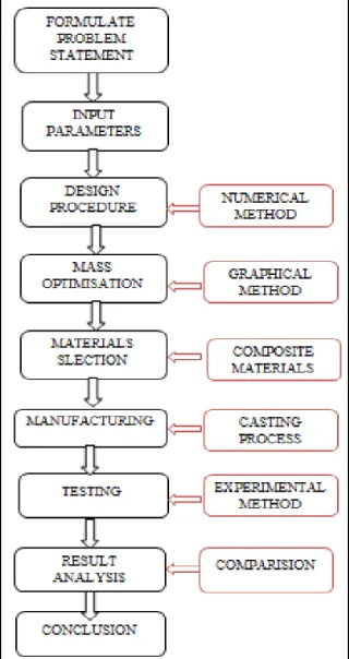
II. PROJECT OVERVIEW
First Phase - Formulation Problem Statement
In formulation of the problem statement for this study, extensive preliminary literature studies are required.
The concepts of “Flywheel” are required to be further explored and examined before forming the aims, objectives and scopes. Sources of references will include journals, technical reports, proceedings, publishing on the Internet and books.
The aims, objectives and scopes will then be established together with the discussion in order to formulate the direction of the thesis.
Second Phase – Project Design
Project Design includes the steps which are going to follow the Project Objectives: Input Parameter
The input parameter is finding out which is required while designing the flywheel.
Some of them which are assumed at the initial stage are list out and write from Design Data Book. Design Procedure
It includes Numerical method.
Design parameters are list out and define the steps for the calculation of that parameter. But before that we have to select which type of flywheel get design whether it is solid disc or web/rim type of flywheel.
Depending upon the type of flywheel, Design procedure we will adopt.
Mass Optimization method
In this project we concentrate on the way how it will reduce the mass of flywheel to get same energy stored in flywheel or more than that.
Optimization method will use depending on the design variables and constrains.
Objective function, design variable, constraints like behavior and side constraints will form.
Depending on above data suitable optimization method will find out from Reference Book i.e. engineering optimization by S.S Rao.
Design variable will be the diameter and thickness of flywheel which will optimize in order to minimize the mass of flywheel. Behavior Constraints will be Kinetic energy stored in flywheel and its mass moment of inertia.
Side constrains will depends on their availability range and on space limitation. Material Selection Technique
Data collection is first step while material selection.
Appropriate selection of material is significant for the safe and reliable functioning of a part or component.
Answer to all questions will find out. The questions are what are material suitable for flywheel and why. Which is materials we can substitute, find out the properties of material which is essential for flywheel so that flywheel should not break, as flywheel is rotating body , why the need for substitution of material , what is concept of composite materials , what are R & D has done for composite material flywheel so far.
Flywheels are made from many different materials depending on the application. Lead: For Small flywheels found in children’s toys.
Cast iron: in old steam engines.
Cast or nodular iron, steel or aluminum: in cars to smooth power-transmission may be made of depending on the performance application.
High-strength steel or composites: in vehicle power storage and braking systems.
Selection is based on material properties like cast iron has higher mass and less angular speed and high strength, Aluminum, maraging steel and E- glass composites lies in between cast iron. Carbon Fiber composites used in flywheel with less mass and low density as compared to cast iron.
Composite materials with low densities, low modulus, high strength is suitable for constant stress portion, and with high density, high modulus, high strength is suitable for constant thickness portion.
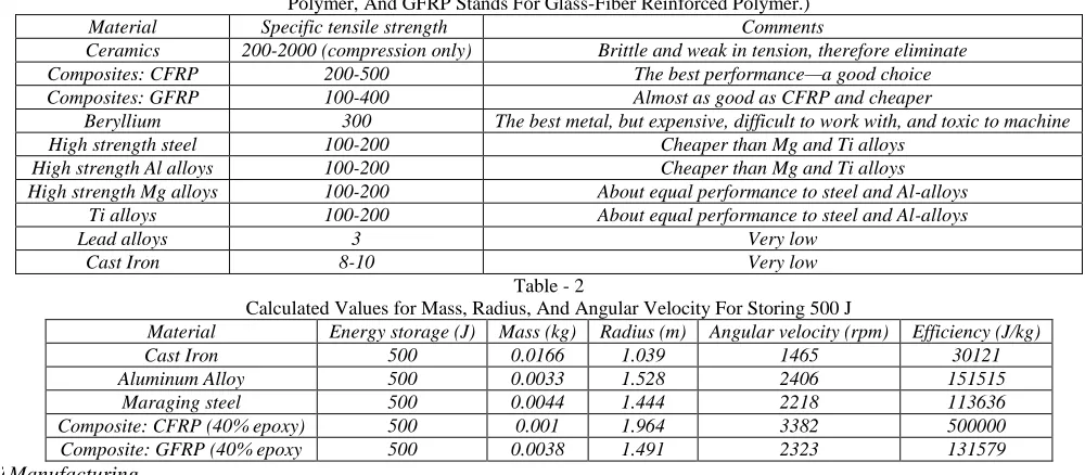
As we required high energy density we use constant stress portion. Some of data are in tabular form:
Table - 1
Calculated Value For Materials And Comments On Their Viability For Flywheel Applications. (CFRP Stands For Carbon-Fiber-Reinforced Polymer, And GFRP Stands For Glass-Fiber Reinforced Polymer.)
Material Specific tensile strength Comments
Ceramics 200-2000 (compression only) Brittle and weak in tension, therefore eliminate
Composites: CFRP 200-500 The best performance—a good choice
Composites: GFRP 100-400 Almost as good as CFRP and cheaper
Beryllium 300 The best metal, but expensive, difficult to work with, and toxic to machine
High strength steel 100-200 Cheaper than Mg and Ti alloys
High strength Al alloys 100-200 Cheaper than Mg and Ti alloys
High strength Mg alloys 100-200 About equal performance to steel and Al-alloys
Ti alloys 100-200 About equal performance to steel and Al-alloys
Lead alloys 3 Very low
Cast Iron 8-10 Very low
Table - 2
Calculated Values for Mass, Radius, And Angular Velocity For Storing 500 J
Material Energy storage (J) Mass (kg) Radius (m) Angular velocity (rpm) Efficiency (J/kg)
Cast Iron 500 0.0166 1.039 1465 30121
Aluminum Alloy 500 0.0033 1.528 2406 151515
Maraging steel 500 0.0044 1.444 2218 113636
Composite: CFRP (40% epoxy) 500 0.001 1.964 3382 500000
Composite: GFRP (40% epoxy 500 0.0038 1.491 2323 131579
Manufacturing
From design, detail drawing will draw using Catia (CAD software).
With drawing of flywheel and materials we will go for manufacturing the flywheel. Casting method is suitable for flywheel.
While manufacturing the flywheel, we will only go for composite material flywheel, not for the cast iron which is normally used.
Testing
It will include experimental set up.
It will check experimentally whether composite flywheel gives us the value of energy stored as that of value which is calculated by analytically.
Result Analysis
We will do the analysis of result.
It will include checking, comparison of result from Analytical as well as experimental method. Conclusion
Conclusion will formulate so that we will firmly say that composite flywheel with this design is best and we can use approach for society.
Third Phase – Report Writing
This will involve substantial submission of write up, organizing the data format and outline Constant discussion with the superiors throughout the write up processes, until the approval of draft, amendment draft and finally the Final Manuscript.
III. METHODOLOGY
In present work we will use two research methodology i.e. one is Numerical Method and second one is Experimental Method. Result will be calculate with the help of Numerical Method and check or validate with experimental value with the help of Experimental Method. Details information or what should be done in this two method is as discussed below.
Numerical Method
Input Parameter
Fluctuation of Energy ∆E (Nm) Mean Speed N (rpm)
Coefficient of Speed fluctuation CS Design Procedure
Mass of Flywheel
Tensile stress due to the centrifugal force
V= π D N/60 Cross- sectional dimensions of rim:
t = Depth or thickness of the rim (meter)
b = Width of the rim (meter) =2t …….(Assume) ρ = Density of material (kg/m3)
Cross- sectional area of rim A = bt Mass of flywheel = AπDρ
Diameter and length of Hub: d = diameter of Hub
d1 = diameter of the shaft l = Length of Hub Tmax = 2 Tmean
Maximum Torque acting on shaft Tmax = τ (d1)3π / 16.
The diameter of the hub is made equal to twice the diameter of shaft and length of hub is equal to width of the rim. d = 2 d1
l = b Cross-sectional dimensions of the elliptical arms
Let a1 = Major axis,
b1 = Minor axis = 0.5 a1 ...(Assume) n = Number of arms
σb = Bending stress for the material of arms
The maximum bending moment in the arm at the hub end, which is assumed as cantilever is given by M = T (R – r) / R n
Section modulus for the cross-section of the arm,
Z = π × b1 (a1)2/ 32 Dimensions of Key
The standard dimensions of rectangular sunk key depend on shaft diameter Width of key, w
Thickness of key
The length of key (L) is obtained by considering the failure of key in shearing. Maximum torque transmitted by the shaft (Tmax), = L × w × τ × d1 / 2
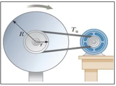
Experimental Method
Fig. 2: Experimental Set Up
Experimental Set up consist of components like – Motor : 1 HP
Smaller (on motor shaft) and Bigger Pulley (shaft) Shaft
Bearing (at two ends of shaft)
IV. DESIGN CALCULATION
Design Consideration
Type of flywheel : Solid disc Flywheel
Velocity for flywheel v ≤ 25 m/s for ordinary grey CI flywheel. For solid disc type of flywheel, D ≤ 300 mm.
Assume v = 20 m/s (it is safe) and mass of flywheel=10 Kg.
Input Parameter
Fluctuation of Energy ∆E (Nm) = 28 Nm Mean Speed N (rpm) = 1440 rpm
Coefficient of Speed fluctuation CS = 0.007
Calculations
Mean Diameter of flywheel (D) =
v × 60 /(π × N) (20 * 60) / (π * 1440)
0.25 m 254.14 mm [ ((D – 0.5)/5) + 1] * 5
259.14 mm.
Velocity of flywheel (v) = (π * D *N) /60000 19.53 m/s
Mass of flywheel (m)
= ∆E / v2 Cs
28 /(19.532)*0.007
= 10.48 Kg
Width of Solid disc flywheel (b)
= mass/ ((π /4)* ((D/1000)2) * ρ = 10.48 /((π /4)* ((259.14/1000)2) * 7100
= 0.027 m
= 27.98 mm
= [ ((b – 0.5)/5) + 1] * 5
= 32.48 mm
Maximum Strength ( σmax) = ((3 + μ)/8) * ρ(ɷ2)(D2/4)
ɷ = (2 * π *N)/60
= 150 rad/sec
σmax = 923323.05 N/m < 20 * 106 N/m
Design is safe Let us assume that shaft is overhang by some amount and act as cantilever beam.
Overhang = ((length of bearing)/2) + (width/2) + clearance Since the length of bearing is not known, we assume that overhang length l = 200 mm.
Bending Moment , (M) = Weight of flywheel * overhang = 10.48 * 9.81 * 0.2 = 20.56176 Nm Mean Torque , (T) = (60 * P)*(2 * π *N) = (60 * 750)/(2 * π *1440) = 4.976 Nm
We assume that shaft is subjected to heavy shock load for which shock and fatigue factors Cm and Ct are 2.0, 1.5 resp. Therefore,
Equivalent Torque, (Teq) = = = 41.79Nm.
Assume that the shaft is made of medium carbon steel having torsional yield strength Therefore,
τd = τy / Factor of safety = 250/5 = 50 N/mm2
Shaft Diameter (d) = [(16 Teq)/(π τd)]^(1/3) = [(16*41.79*1000)/(3.14*50)]^(1/3) = 16.21Nm
Hub Diameter (dh) = 2 * d = 2 * 16.21 = 32.42 mm
Length of Hub (l) = 2.5 * d = 2.5 * 16.21 = 40.525 mm
V. FUTURE SCOPE
In this project, we will design and develop and optimization of flywheel using the combination of material instead of using one material flywheel. Scope of this project is limited because flywheel which are used in machine having bigger in size. So we cannot go for higher dimensions of flywheel. We will design the flywheel with respect to small size. Aim of this project is not only to manufacture but also checking whether we will use any other material instead of common material which is already used.
Nowadays CFRP has been developed for more strength. CFRP stands for carbon fiber reinforcement polymer and GFRP is Glass Fiber reinforcement polymer. This fiber has made with reinforcement process in order to increase the strength of part and this part is also light weight if we are using these materials. So future scope for this project will be use of these materials and will check that the whether it stores how much of energy as compared of conventional cast iron or cast iron with carbon fiber (composite) flywheel.
VI. CONCLUSION
Project is based on design, development and optimization of flywheel using composite material. Flywheel is mechanical device which is used to store energy whenever required for machine or automobile etc. The amount of energy stored is directly proportional to square of its rotational speed. Flywheels have mass moment of inertia and thus resist changes in rotational speed. That means flywheel requires some weight to stored energy and so flywheel is so bulky. That time we need to optimize the mass of flywheel by considering the energy stored in flywheel and its mass moment of inertia as constraints. To reduce the mass either we go for changing the dimensions like diameter and thickness of flywheel or by using or selecting such material which gives the same value or larger value of energy storage than energy stored with single material flywheel.
The project is discussed about the variable material or composite material flywheel so that it gives same value (or more than that) of energy stored in flywheel with minimum mass as compared to cast iron flywheel. It is achieved by two methodology i.e. numerical method and experimental method. In this project we use tow materials cast iron and carbon fiber for flywheel which gives good strength and also it will be light in weight.
REFERENCES
[1] Metwalli, S. M. G. , Shawki S. A., Sharobeam M. H . "Optimum Design of Variable Material Flywheels ".ASME Trans , (1983) vol 105, pp 249-253
[2] Dr.. McCoy Robert A"Design Development of Advanced Composite Flywheels"., Naval Systems Engineering Department , 1976
[3] Bitterly Jack G. “Flywheel Technology – Past, Present, and 21st Century Projections”. IEEE AES Systems Magzines ,1998
[4] Tzeng Jerome , Emerson Ryan , Moy Paul, “Composite flywheels for energy storage”, Elsevier Composite science and Technology 66 (2006) , 2520-2527
[5] Conteh Michael A. , Nsofor Emmanuel C. “Composite Flywheel material design for high – speed storage energy storage”. ,Science Direct , Journal of applied
research and Technology 14(2016) , 184-190.
[6] Sung K. Ha , Secong J. Kim , Sana U. Nasir , Sang C. Han. , “Design optimization and fabrication of a hybrid composite flywheel rotor ”. , Elsevier, Composite
structures 94(2012) , 3290-3299.
[7] M. Krack, M. Secaneli , P. Mertiny , “Cost optimization of hybrid composite flywheel rotors for energy storage”, Springer-verlag,struct multidisc Optim
(2010)41 : 779-795.
[8] G.R. Kress,”Shape Optimization of a flywheel”, Springer-verlag , struct multidisc optim 19 (1998) , 74-81.
[9] Timothy N. Lambert, Cody M. Washburn, Danae J. Davis, Jennifer Strong, Lee Massey, Ben Anderson, David Calkins , “Next Generation Composite
Materials for Flywheel Development”.
[10] S. J. DeTeresa, S. E. Groves ,“Properties of Fiber Composites for Advanced Flywheel Energy Storage Devices” , U.S . Department of Energy & Lawarence
Livemore National Laboratory, (2001).
[11] Khurmi R. S and Gupta J.K. , “A Textbook of Machine Design” , 14th Revised Edition, S. Chand & company Ltd,Delhi , 2009 , pp. 776-819.
[12] Sharma C.S. Sharma & Purohit Kamlesh , “Design of Machine Elements” , Eastern Economy Edition , PHI learning Pvt Ltd. , 2003 , pp 680-713.
[13] Bhandari V.B , “Machine Design Data Book” , Mc Graw Hill Education New Delhi, 2014 .
[14] Kalaikathir Achchagam , “Design Data” , PSG College of Technology , Coimbatore , 2012