A Novel Solution For Multiplexer As A Micro Heat
Pipe
Sukrut M Sompura
Mechanical Engineering Department, H.C.E.T., Sidhpur, India Email: [email protected]
ABSTRACT: Abstract- Micro heat pipe was used to reduce the heat level in computers and laptops. There is no need any pumping system to reduce the temperature from sunk to sink. It can be used as an isolate component in a multiplexer. It is made from a number of cavity and bracket to support the structure. This multiplexer used to pass the radio frequency. We have found its use in multiplexer for space application. Multiplexer is widely used in satellite and there is temperature reduce and increasing to the face of satellite at sun and at moon respectively. So, a major problem to reduce the stress concentration by the use of different techniques. I have adopted here micro heat pipe as a solution to reduce the temperature gradient. I have used with different orientation angle and different working fluid like Methanol, Water, Acetoneand tilting angle O° , 45° and 90°.
Keywords: Micro heat pipe, multiplexer, working fluid, Sensor
1 INTRODUCTION
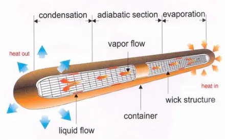
Capillary-driven two-phase systems offer significant advantages over traditional single-phase systems. With the typically increased thermal capacity associated with the phase change of a working fluid, considerably smaller mass flow rates are required to transport equivalent amounts than in single-phase liquid or gas systems for a given temperature range. Moreover, heat transfer coefficients of two-phase systems are much greater than in single-phase flows and result in enhanced heat transfer. The best known capillary-driven two-phase system is the heat pipe [1]. The concept of the heat pipe was first presented, but was not widely publicized until an independent development by at the Los Alamos Scientific Laboratories. Heat pipes are passive devices that transport heat from a heat source (evaporator) to a heat sink (condenser) over relatively long distances via the latent heat of vaporization of a working fluid. With evaporator heat addition, the working fluid is evaporated as it absorbs an amount of heat equivalent to the latent heat of vaporization, while in the condenser section; the working fluid vapor is condensed. Return of the liquid to the evaporator from the condenser is provided by the wick structure. The difference between the capillary radii in the evaporator and condenser ends of the wick structure results in a net pressure difference in the liquid-saturated wick. This pressure difference drives the liquid from the condenser through the wick structure to the evaporator region, thus allowing the overall process to be continuous. Due to the two-phase characteristics, the heat pipe is ideal for transferring heat over long distances with a very small temperature drop and for creating a nearly isothermal surface for temperature stabilization [2]. Additionally, no mechanical pumping systems are required due to the capillary-driven working fluid. Given the wide range of operating temperatures for working fluids, the high efficiencies, the low relative weights, and the absence of external pumps in heat pipes, these systems are seen as attractive options in a wide range of heat transfer applications [3]. Heat pipe is defined as an extremely efficient thermal conductor. Generally, a heat pipe is a heat mover or heat spreading device and it acquires heat from asource andtransfers or spreads it to a sink region.
Figure 1: A schematic diagram of micro heat pipe [4]
2 MICRO HEAT PIPE
In particular, notebook PCs where heat dissipation poses a serious problem due to the small packaging volume, heat dissipation technology has become one of the key technologies. Micro heat-pipe (hereafter denoted as μHP) is capable of coping with this problem, and has been in practical use since 1995 [5].
2.2 SPACE APPLICATION OF HEAT PIPE
gravity. This is not an absolute condition; however, as spacecraft motions can cause local accelerations that can pose problems [7].
3 CASE STUDY
The solution to all of these basic thermal problems on Multiplexer was to employ the use of heat pipes inside the spacecraft component. The basic tenet here is that the heat removed from one part of the spacecraft was used to keep the cooler parts suitably warm, a thermal redistribution system. This thermal design concept provided for heat rejection from the spacecraft by radiant exchange between the equipment like cavity to heat sink for maintaining the temperature of the cavity simultaneously multiplexer [8].
3.1 EXPERIMENTAL TEST SET UP
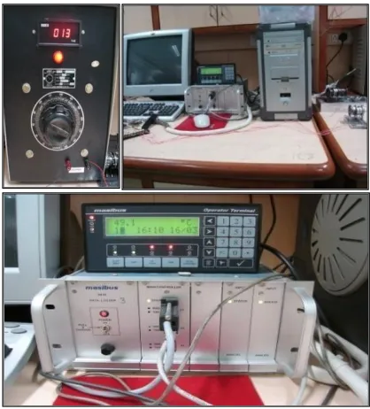
Above said problem of thermo structural stress we have reduced by use of carbon-carbon composite material in place of different material but we can solve that problem in different manner like the use of high conductivity material to reduce the temperature on the cavity and for balancing the temperature difference of MUX channel assembly. As shown in below figure 2 there is an experimental test set up for measuring the performance of heat pipe.
Figure 2 Experimental Test Setup for Measuring Temperature
We have manufactured a heat pipe as shown in Figure 3 and 4, by the use of above design data with the changing in following parameter:
Outer diameter of heat pipe = 3 mm
Inner diameter of heat pipe = 2 mm
Working fluid = water, methanol and acetone
Wick design= Mesh structure with aluminum material
As shown in below figure 5 heat pipe vertical with the horizontal so tilting angle (ø) will be 90° this is the basic condition of this experimental analysis. We have changed the parameter like tilting angle, working fluid and heat source to check that with the changing in such parameter what will be the effect on temperature of cavity and base plate. Attached one sensor inside the cavity is 3.52Ω which can take heat up to 24 watt. We have assemble the bracket with cavity with only one screw so there is not pure touching effect of bracket with cavity so, very less heat transfer happening to purely check the effect of heat pipe.
Figure 5 Assembly of Double Curve Heat Pipe on Base Plate
Reference Condition
Here we need to check the reference condition like without heat pipe and with two brackets which is assemble on base plate of aluminum As shown in table 4 data of reference condition shown i.e. without heat pipe. There is a temperature difference between cavity and base plate (ΔT=temperature difference between cavity and base plate in °c) which is the same for all experiment.
Figure 6 One Cavity Fitted with two Brackets on Base Plate
Bracket
Sensor Heat pipe Heater
Figure 3 Single Curve One Side Heat Pipe One Water and another Methanol as Working Fluid
Table 1 Experimental Test Results for Reference Condition Here I have used four cases as a working fluid and tilting angle combination.
Option 1:
Boundary condition:
W.f. = acetone
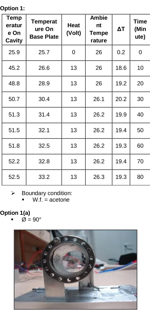
Option 1(a)
Ø = 90°
Figure 7 Single Curve two Heat Pipe at Ø = 90° on Cavity
Temperat ure On Cavity
Temper ature On Base Plate
Heat (Volt)
Ambien t Temper ature
ΔT Time (Minut e)
24.5 24 0 23.8 0.5 0
42.3 27.6 13 23.3 14.7 10
43 28.7 13 23.3 14.3 20
43.7 29.8 13 23.2 13.9 30
42.9 30.3 13 23.3 12.6 40
43.7 30.8 13 23.2 12.9 50
42.9 30.8 13 23.1 12.1 60
43.8 30.7 13 23.1 13.1 70
43.5 30.8 13 23.1 12.7 80
Table 2 Experimental Test Results at 90° Tilting Angle
Option 1(b): Ø = 45°
Figure 8 Single Curve two Heat Pipe at Ø = 45° on Cavity
As shown in figure 9 chart of tilt angle v/s ΔT (temperature difference between base plate and cavity) of acetone as a working fluid heat pipe at different tilting angle of heat pipe. The base plate’s temperature e.g. as shown in table 3 temperature of base plate from 24.9 to 32.0 °c, whereas the temperature on cavity is from 25 to 47.1 °c after 80 min when ∆T is less than it is good result in terms of heat pipe’s performance. Because when temperature increases of the cavity due to heat source as shown in figure 5 then heat pipe will transport more heat from the evaporator to condenser section. So, increase in temperature of base plate is due to the heat pipe. Here we have limited our angle orientation criteria up to only two different angle because it easy to orient in actual application of space craft component.
Temp eratur e On Cavity
Temperat ure On Base Plate
Heat (Volt)
Ambie nt Tempe
rature ΔT
Time (Min ute)
25.9 25.7 0 26 0.2 0
45.2 26.6 13 26 18.6 10
48.8 28.9 13 26 19.2 20
50.7 30.4 13 26.1 20.2 30
51.3 31.4 13 26.2 19.9 40
51.5 32.1 13 26.2 19.4 50
51.8 32.5 13 26.2 19.3 60
52.2 32.8 13 26.2 19.4 70
Figure 9 Chart of Tilt Angle V/S ∆T Of AcetoneHeat Pipe
Table 3 Experimental Test Results at 45° Tilting Angle
Option 2:
Boundary condition:
W.f. = water
Option 2(a):
Ø = 90°
Figure 10 Single Curve two Heat Pipe at Ø = 90° on Cavity 0
15 30 45 60 75 90 105
1111.51212.51313.51414.51515.51616.51717.518
Ti
lt
an
gl
e
,ø
∆T
Tilt angle v/s ∆T
0 degree
90 degree
Tempera ture On Cavity
Tempera ture On Base Plate
Hea t (Vol
t)
Ambie nt Temper
ature
ΔT
Time (Minut e)
25 24.9 0 23.7 0.1 10
44.3 28.4 13 23.7 15.9 20
46.7 30.4 13 23.7 16.3 30
46.5 31.6 13 23.7 14.9 40
46.9 32 13 23.7 14.9 50
47.5 32.7 13 24.5 14.8 60
47.7 33.1 13 24.8 14.6 70
48.2 33.2 13 24.8 15 80
Temperat ure On
Cavity
Temper ature
On Base Plate
Heat (Volt)
Ambie nt Tempe
rature
ΔT Time (Minute)
25.9 25.9 0 25 0 0
46.7 30.4 13 25 16.3 3.52
48.2 33.1 13 25 15.1 3.52
48.8 34.2 13 25 14.6 3.52
49.1 34.9 13 25 14.2 3.52
49.3 35.1 13 25 14.2 3.52
49.6 35.4 13 25 14.2 3.52
49.7 35.4 13 25 14.3 3.52
Table 4 Experimental Test Results at 90° Tilting Angle
Option 2(b):
Ø = 0°
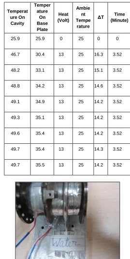
Figure 11 Single Curve two Heat Pipe at Ø = 0° on Cavity
Table 5 Experimental Test Results at 0° Tilting Angle
Figure 12 Chart of Different Working Fluid v/s ΔT at Different Tilting angle
As shown in figure 12 chart of different tilt angle of heat pipe v/s ΔT (temperature difference between base plate and cavity). The base plate’s temperature e.g. as shown in table 5 from 25.9°C to 35.5°C, whereas the temperature on cavity is from 25.9 to 49.7°C after 80 min. From the figure 12 we can see that at the 0° tilting angle ∆T is higher than 90° tilting angle and at 0° orienting angle is indicaticating good result in compare to 90°. So, heat pipe’s orienting angle should be 0° according to our heat pipe’s design then it will operate at its efficient level.
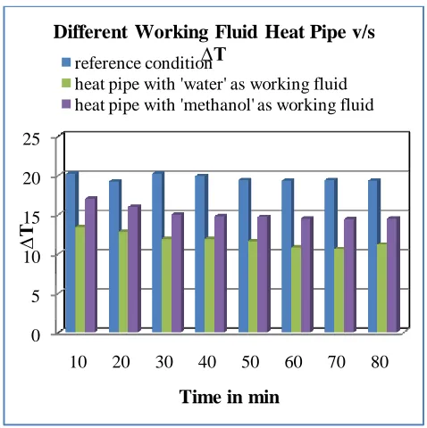
Figure 13 Chart of Time V/S Temperature Difference for Different Working Fluid
As shown in figure 13 there is a comparison of different working fluid of heat pipe we can depicts from figure 13 that reference conditions’ ∆T is higher than another heat pipe’s and working fluid as a water in heat pipe is good than acetone and methanol working fluid’s heat pipe.
8 10 12 14 16 18 20 22 24
10 20 30 40 50 60 70 80
∆T
Time in min.
Time v/s ∆T
0 degree
90 degree
0 5 10 15 20 25
10 20 30 40 50 60 70 80
∆T
Time in min
Different Working Fluid Heat Pipe v/s
∆T
reference condition
heat pipe with 'water' as working fluid heat pipe with 'methanol' as working fluid Tempe
rature On Cavity
Tempera ture On Base Plate
Heat (Volt)
Ambie nt Tempe
rature
ΔT Time (Minute)
25.3 25.7 0 24.3 0.4 0
42.3 28.9 13 24.4 13.4 10
44.2 31.4 13 24.4 12.8 20
44.4 32.5 13 24.4 11.9 30
44.9 33 13 24.4 11.9 40
45.8 33.5 13 24.4 11.6 50
44.9 34.1 13 24.4 10.8 60
44.9 34.3 13 24.4 10.6 70
CONCLUSION
We can conclude that by the use of heat pipe we can reduce the temperature on base plate so, ultimately the temperature of multiplexer also be reduced as per the cavity temperature. By the use of 0 tilting angle and the working fluid water is the best combination to improve the performance of the micro heat pipe.
4 REFERENCES
[1]. I.C. Bang, S.H. Chang, “Boiling heat transfer performance and phenomena of Al2O3–water nanofluids from a plain surface in a pool”, Int. J. of Heat and Mass Transfer 48 (12) (2005), pp. 2420– 2428.
[2]. Swanson L. W.: “Heat pipe, Heat and Mass
Transfer”, Mechanical Engineering Handbook, Ed.
Frank Kreith Boca Raton: CRC Press LLC, 1999.
[3]. ISRO website
http://www.isro.org/isrocenters/sac.aspx
[4]. G. P. Peterson and A. K. Mallik, J. “Electronic Packaging”, vol. 117, pp. 82-87, 1995.
[5]. A.R.srinivas, “A technical report on mechanical design, development and realization of 7 –ch
KU-band output multiplexer”, Space Application
Centre, ISRO, Ahmadabad, June 2004.
[6]. Chi, S.W.: “Heat pipe theory and practice”, Hemisphere publishing, Washington, DC.1976.
[7]. Zohuri, B.: “Heat Pipe Design and Technology: A
Practical Approach”, Galaxy Advanced
Engineering, Hillsborough, CA, USA 2011.