ISSN (e): 2250-3021, ISSN (p): 2278-8719
Vol. 08, Issue 7 (July. 2018), ||V (II) || PP 27-32
Drag Reduction of an After Burner Flame Stabilizer in Passive
Condition
Rakesh.C
1, Jafar M Sayed
2, M S Ganesha Prasad
31Dept. of Mechanical Engineering, New Horizon College of Engineering,
2
Dept. of Mechanical Engineering, New Horizon College of Engineering,
3Dept. of Mechanical Engineering, New Horizon College of Engineering,
Corresponding Author: Rakesh.C
Abstract:
The technique of placing bluff bodies in downstream will nearly reduce the drag generated by single bodies. numerous numerical and test results have proved this phenomenon of drag reduction due to flow interference and placing the bluff bodies upstream and downstream of the flame stabilizer. A v-shaped gutter flame stabilizer is mostly used in afterburner of an aircraft turbine engine, which is used to hold the flame when the afterburner is in active condition. But when the burner is in passive condition the presence of gutter produce excess drag and pressure loss in the after burner section of the engine. Therefore it is important to reduce the pressure loss and drag generated by the flame stabilizer in afterburner. In this work an attempt has been made to understand the flow physics involved in keeping bodies in tandem and the effect of change in drag coefficient comparing to the single bodies. Three types of configuration of bodies are investigated considering the factors affecting the drag and the drag coefficient is calculated. The models are designed in CATIA V5 and the computational fluid dynamic analysis is done using ANSYS fluent software.Keywords:
Afterburner flame stabilizer, Drag reduction, Aerofoil shape gutter, v-shaped gutter, tandem bodies.--- --- Date of Submission: 22-06-2018 Date of acceptance: 07-07-2018 --- ---
I.
INTRODUCTION
In aircraft application, larger thrust for small duration is required sometimes and can be achieved by two methods. First method is by increasing the mas flow rate and the other is by thrust augmentation. Flame stabilizer is employed to hold and stabilize the flames, which are placed after the turbine section in an afterburner. Bluff bodies are characterized by large region of separated flow, a direct consequence of which is that they suffer from large values of Cd. Various research and development are carried out improve the
performance of afterburner, both experimentally and theoretically. Computational methods have become highly useful tool to design, develop, and analyze the performance of an afterburner before implementing. The amount of drag generated by the presence of flame stabilizer and the recirculation zones in the wake of the stabilizer are very important factor to be considered for better performance of an afterburner in any gas turbine engines. In the past, various research activities have been carried out to reduce the drag of bluff bodies, by varying the orientation and arrangement of the bluff body such as, tandem, staggered, normal, and perpendicular to the flow. The above researches were carried out through CFD using ANSYS fluent software.A brief review of literature related to the above studies are presented.
Nakanishi et al... [1] Conducted experimental investigations on the effect of flame holder gutter shape on afterburner performance. Conventional v-gutter has minimum drag and minimum pressure loss both in burning and without burning condition and the flame holder shape had less effect on stability limits.
gutter, where as it is comparatively higher when it is kept upstream of the gutter.
II.
METHODOLOGY
• Firstly, the case study on the different types of flame stabilizer geometries are done. • The design parameters and the boundary conditions are determined.
• Validation of the Cd value from a research paper is compared with the CFD analysis value done in our software by taking the same boundary condition.
• The modeling of different geometries are done considering the factors affecting the drag using the CATIA V5 software.
• Then the meshing is done using ANSYS V.16 software.
• The fluid flow analysis is done using Ansys FLUENT to obtain forces acting on the geometries and Drag coefficient is calculated using Drag Equation.
• The results are compared and optimum results for better performance of afterburner is chosen.
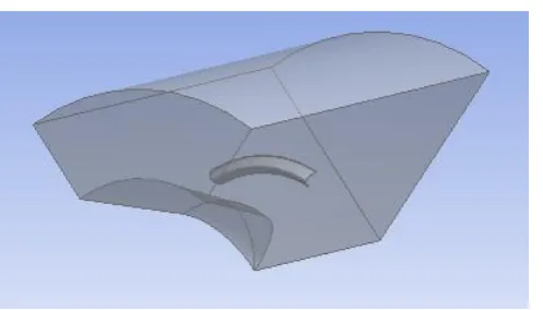
ANSYS fluent software is used for the computational fluid dynamics analysis of flow over a V-gutter. The boundary conditions for above analysis are given in the table 1. A steady, viscous flow is considered and k-ɛ turbulence model is taken for the analysis. Standard wall function is chosen with v-gutter as no slip wall. A computational fluid domain is created surrounding the v-gutter model which is taken from the literature survey which corresponds to the section of an afterburner as shown in the figure 2.1. The analysis is carried out for the three different configuration of the bluff bodies each having three different cases. Drag coefficient is calculated using the drag force obtained by the software in the drag equation.
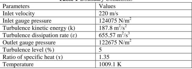
Table 1-Boundary Conditions
Parameters Values
Inlet velocity 220 m/s Inlet gauge pressure 124075 N/m2 Turbulence kinetic energy (k) 187.8 m2/s2 Turbulence dissipation rate (ɛ) 655.57 m2/s3 Outlet gauge pressure 122675 N/m2 Turbulence level (%) 5
Ratio of specific heat (ɤ) 1.35 Temperature 1009.1 K
Drag Equation is used to find the drag coefficient.
Cd= Fd
0.5 ∗ρ∗ v2∗ A
Where,
Cd - Coefficient of Drag.
Fd - Drag force in Newton.
A - Projected area on a plane perpendicular to the direction of motion in m2. ρ - Density of the fluid in Kg/m3.
Fig-2.1 Computational fluid domain
The density and viscosity of the fluid is calculated and is constant for all the cases which are carried out and their values are 0.778 Kg/m3 and 4.367*10-5 Kg/m-s respectively. Velocity ahead of the v-gutter is taken as 130 m/s and is also constant for the entire configuration.
III.
RESULTS AND DISCUSSION
Coefficient of drag is calculated and flow over the bare v-gutter and when the bluff bodies are placed downstream are observed. Three different configurations were studied considering the factors affecting the drag and compared. The results show reduction of drag over the v-gutter with the bluff bodies placed downstream when compared with the bare v-gutter.
3.1 Case 1- Increasing the Apex Angle of the V-Gutter
One of the factors affecting the drag is inclination angle to the flow. According to the literature survey for 30o apex angle the drag coefficient is found to be 1.08, taking this as a reference the study is carried out. In this case the v-gutter apex angle is increased from 30o to 35o whereas the depth of the v-gutter is kept same. The drag force obtained from the CFD fluent software is used in the drag equation and coefficient of drag is calculated to be as 1.07.
0.93
0.91
0.95
0.91 0.92 0.93 0.94 0.95 0.96
ef
ficient
o
f
dra
g
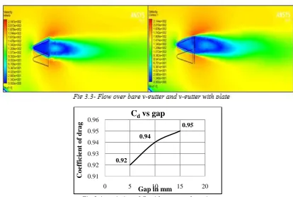
varied to 5mm, 10mm and 15mm and the drag coefficient were calculated to be as 0.92, 0.94 and 0.95 respectively. Hence it can be observed clearly that the reduction of drag obtained is maximum 11.5% and minimum 8.7% for this geometry. Fig 3.3 shows the flow over bare v-gutter and v-gutter with plate. Fig 3.4 shows the variation of Cd with respect to spacing.
Fig 3.4- variation of Cd with respect of spacing
3.3 Case-3: Aerofoil Shape Gutter
Shape is one of the important factors affecting the drag. In this case the gutter is in the form of an aerofoil and the coordinate are of NACA 0012 Aerofoil and the depth is kept same. The drag force obtained from the CFD fluent software is used in the drag equation and coefficient of drag is calculated to be as 0.98. Keeping this value as the base, rounded edged disk is placed downstream of the gutter. The distance between the disk and the v-gutter was varied to 5mm, 10mm and 15mm and the drag coefficient were calculated to be as 0.851, 0.853 and 0.89 respectively. Hence it can be observed clearly that the reduction of drag obtained is maximum 13.5% and minimum 8.6% for this geometry. Fig 3.5 shows the flow over bare v-gutter and v-gutter with plate. Fig 3.6 shows the variation of Cd with respect to spacing.
0.92 0.94
0.95
0.91 0.92 0.93 0.94 0.95 0.96
0 5 10 15 20
Co
ef
ficient
o
f
dra
g
Fig 3.6- variation of Cd with respect of spacing
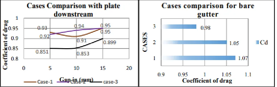
3.4 Comparison of cases
After the overall results are achieved and analysis is completed the comparison is been made. Fig 3.7(a) shows the comparison for v gutter with plate downstream, it can be seen from the above fig that the case 3 which is aerofoil shape gutter is more efficient when compare to other two cases. When v gutter shape is required then case 1 is better than the case 2. Fig 3.7(b) shows the comparison for all the cases when no plate is placed downstream of the gutter. Comparing the above results it can be said that the aerofoil shape gutter is more efficient than the v-gutter shape flame stabilizer.
Fig-3.7(a) &3.7(b) Comparison of Cases
IV.
CONCLUSION
It can be concluded from the CFD analysis carried out that the drag can be reduced by placing the bluff bodies downstream of the V-gutter. It can be observed from the above studies that coefficient of drag is less when compare to the bare gutter and further the drag varies with respect to the spacing between the gutter and
0.851 0.853
0.899
0.84 0.86 0.88 0.9 0.92
0 5 10 15 20
Co
ef
ficient
o
f
dra
g
International organization of Scientific Research
32 | P a g e
pp.104-111, March-1980.
[4]. A.Prasad and C.H.K. Williamson, A method for reduction of bluff body drag, Journal of wind engineering and Industrial aerodynamics, Vol-69-71, pp.155-167, Jul-Oct-1997.
[5]. S Srinivasan, J J Isaac, C.Rajashekar, A.Arokkiaswamy, Drag reduction of V gutter of an afterburner by
tandem bluff bodies using CFD, OSR Journal of Mechanical and Civil Engineering (IOSRJMCE),
Aug-2012
[6]. P.F.Zhang, J.J.Wang, S.F.Lu.J.Mi, Aerodynamic characteristics of square cylinder with a rod in
staggered arrangement, Experiments in Fluids, Volume 38, Issue 4, pp.494-502, March-2005.
[7]. Mehdi R. Khorrami, David P. Lockard, Meelan M. Choudhari, Luther N. Jenkins,Dan H. Neuhart, and Catherine B. McGinley “Simulations Of Bluff Body Flow Interaction For Noise Source Modeling” Report
Number: AIAA Paper 2006-3203.
[8]. V.Ganesan, Numerical computation of turbulent flow behind a conical baffle Indian journal of Technology, Vol-18, pp.447-450, Nov-1980.
[9]. Shaik ShahabazAhamed, Dr. K.M Parammasivam “Experimentation Of Flame Stabilization Using Strong
Swirl For Afterburner Applications” Proceedings of International Conference on Advanced Engineering
and Technology-2015
[10]. Anand R, Lokesharun D, Rajkumar S, Kirubakaran R “3D CFD Analysis In An Afterburner Using
Numeca”. International Journal of Advanced Research in Engineering & Management (IJAREM) 2017.