A Model-Based Software Development Method for
Automotive Cyber-Physical Systems
Zhigang Gao1, Haixia Xia2, and Guojun Dai1
1 College of Computer Science, Hangzhou Dianzi University,
Hangzhou 310018, China
[email protected], [email protected]
2 College of Informatics & Electronics, Zhejiang Sci-Tech University,
Hangzhou 310018, China [email protected]
Abstract. The development of automotive cyber-physical systems
(CPS) software needs to consider not only functional requirements, but also non-functional requirements and the interaction with physical environment. In this paper, a model-based software development method for automotive CPS (MoBDAC) is presented. The main contributions of this paper are threefold. First, MoBDAC covers the whole development workflow of automotive CPS software from modeling and simulation to code generation. Automatic tools are used to improve the development efficiency. Second, MoBDAC extracts non-functional requirements and deals with them in the implementation model level and source code level, which helps to correctly manage and meet non-functional requirements. Third, MoBDAC defines three kinds of relations between uncertain physical environment events and software internal actions in automotive CPS, and uses Model Modifier to integrate the interaction with physical environment. Moreover, we illustrate the development workflow of MoBDAC by an example of a power window development.
Keywords: Automotive cyber-physical systems, non-functional
requirements, physical environment, model-based methods, model transformation, code generation.
1.
Introduction
such as timeliness, energy, memory, safety and reliability, and the interaction with physical environment.
In the recent two decades, both academia and industry have made efforts to explore approaches which are more applicable to the development of embedded software, such as the real-time object-oriented modeling (ROOM) [5], the UML-RT (implemented by IBM Rational Rose) [6], the Specification
and Description Language (SDL), a language widely used in
telecommunications domain [7], and Model-integrated Computing [8]. Among them, the model-based development of embedded software has become one of the most promising methods.
The current research on model-based development of embedded software basically focuses on high-level modeling and simulations (e.g. Ptolemy [9]), or integration methodologies of tools (e.g. MoBIES [10]) for embedded software, but seldom involves a suite of complete implementation for a specific domain and considers both the non-functional requirements and environment requirements. Although there are a few of model-based CPS development methods [11-12], these methods only stay on high-level design model or require well-defined components. In this paper, we propose MoBDAC, which supports the implementation under the OSEK/VDX (Open Systems and the Corresponding Interfaces for Automotive Electronics (in German)/Vehicle Distributed eXecutive (in French)) specification [13]. MoBDAC covers the whole development workflow of automotive CPS applications from modeling and simulation to code generation. MoBDAC helps to increase development efficiency and improve software quality, and it is easy to integrate the interaction with physical environment.
The rest of this paper is organized as follows. Section 2 summarizes the related work. Section 3 presents the architecture of MoBDAC. The implementation process is presented in section 4. In section 5 we illustrate the implementation of a power window control system as a case study and discuss the characteristics of MoBDAC. We conclude this paper in section 6.
2.
Related Work
Ptolemy is one of the first research projects in the model-based development of embedded software. Ptolemy II [9], the current modeling tool of Ptolemy, is a hierarchical heterogeneous modeling environment for modeling, simulation, and design of concurrent, real-time, embedded systems. The purpose of Ptolemy II is to provide a trial platform for heterogeneous models of computation (MOC). Ptolemy II supports many kinds of MOC, such as synchronous dataflow (SDF), process networks (PN), finite-state machines (FSM), etc. Different components can be hierarchically integrated into a complex system under the government of different MOC. GME (The Generic
Modeling Environment) [14] is a domain-specific meta-modeling
Systems
modeling process includes third phases: meta-modeling, modeling, and system-modeling. MoBIES (Model-Based Integration of Embedded Software) [10] is a tool chain for the integration of reusable embedded software. MoBIES integrates several kinds of existing commercial and academic tools to cover the modeling, model analysis, code generation, and runtime analysis in the development of embedded software, and uses standard XML file formats to exchange information among different tools. Currently, many commercial model-based development tools, such as Matlab/Simulink [15], MetaEdit+ [16], DOME [17], Rhapsody [18], etc., have been used to the development of embedded software, such as automotive electronic or avionic controlling software.
In recent years, CPS software development has been attracting more and more attention. Woo et al. [19] present a formal software development method with a suite of feedback control laws and efficient resource monitoring mechanism to deal with system failure effectively. Lin et al. [20] present an integrated simulation method in order to accurately reflect the operation and interaction between the cyber aspects and the physical aspects of CPS. Ma et al. [21] present a high-confidence cyber-physical alarm system (CPAS) and discuss its requirements, system models and implementation.
A few of research efforts have been made to develop CPS software with model-based methods. Magureanu et al. [11] present a model-based CPS development method for gas distribution. Their method mainly focuses on building the high-level models using UML. Bhatia et al. [12] present a model-based framework called SysWeaver to model, integrate, analyze, verify, and implement AUTOSAR-compliant automotive systems, which extends AUTOSAR (Automotive Open System Architecture) in order to meet the real-word requirements of automotive CPS, such as timeness, fault tolerance, feedback, etc. In the development of automotive systems, SysWeaver requires the components are available and have well-defined parameters.
3.
The Architecture of MoBDAC
Code
Models in implementation domains System
specifications
Software specifications Physical Environment Concern Table
Models in problem domains
Model transformation Non-Functional
Concern Table
Model Modifier
Code generation Analysis tools
Function extraction
Modeling Non-function
extraction
Physical environment
extraction
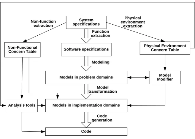
Fig. 1. Architecture of MoBDAC
3.1. Function Extraction
The purpose of function extraction is to extract software specifications from system specifications of automotive CPS. For automotive CPS, their system specifications include the following three aspects.
Functional requirements. Functional requirements define the behavior
of a system and what the system does [22]. In automotive CPS, functional requirements define what functions they include, the operating process when completing a function, and the relations among different operations, etc. Developers can specify the functional requirements of automotive CPS according to what functions their subsystems (such as the body subsystem, the safety subsystem, etc) include, and how to carry out these functions.
Non-functional requirements. Non-functional requirements define the
quality of a system and how well the system should work [22]. Non-functional requirements specify global constraints [23], such as timeliness, safety, fault-tolerance, energy, etc [24-26]. Developers can specify the non-functional requirements of automotive CPS according to the global constraints from systems specifications.
Physical environment requirements. For automotive CPS, different
Systems
requirements define the interaction modes and requirements between automotive CPS software and their physical environment. For example, for an in-vehicle air-conditioning system, it detects the temperature and humidity in the vehicle, and decides its working status; for a backup radar, it detects the distance between the vehicle and obstacles, and decides its alarm status.
When performing function extraction, it only extracts the function requirements and put them into software specifications. The non-functional requirements and the interaction with physical environment are extracted by non-function extraction and physical environment extraction, and put them into Non-Functional Concern Table and Physical Environment Concern Table respectively.
3.2. Modeling
System specifications and software specifications are all text which is mainly used to communicate among designers. During modeling, we build MPD which denote the structures and functions of software from software specifications, and verify their correctness by simulation. MPD describe the structures of software, the relations among different parts, and the transition relations among different states.
Because they do not consider the characteristics of deployment platforms, MPD belong to Platform Independent Models (PIM), MPD are more suitable for designers to concentrate themselves on high-level function design and can enhance the portability of software. Moreover, there is a Model Modifier in the right of Figure 1. Model Modifier can build the relations between external physical environment events and software internal actions according to some rules, and then modify MID in order to make the modeling and simulation in MPD independent of physical environment. In automotive CPS, some physical environment events are certain. For example, in-vehicle temperature need be detected at a specific period. For certain interaction with physical environment, it is enough to model its behavior in functional requirements. For uncertain physical environment events, MoBDAC defines three kinds of relations between physical environment events and software internal actions.
Correlative relation. When a physical environment event occurs, a
corresponding software internal action must happen. For example, it is a correlative relation between a physical event of turning on an in-vehicle light and a software action that the state of the in-in-vehicle light turns from off to on. Developers can model the state of the in-vehicle light in problem domains to denote the effects caused by the corresponding physical event.
obstacle event occurring. Developers can model the software action in problem domains and process the results caused by the physical event in the reverse logic.
Complementary relation. A physical environment event maybe
happens when a software internal action occurs. For example, a wheel slip maybe occurs when a brake action is executing. Developers can model the software action in problem domains and detect the physical event in the software action.
In automotive CPS, developer can use correlative relation and exclusive relation to describe the interaction between passive reaction systems (e.g., Power Window System, Supplemental Restraint System, etc.) and physical environment, and complementary relation to describe the interaction between active reaction systems (e.g., Anti-lock Brake System, Anti Slip Regulation, etc.) and physical environment. Using these three relations, developers can model and simulate software functions in MPD without considering the influence of the uncertain physical environment events, Model Modifier adds the interaction with physical environment to MID after model transformation.
3.3. Model Transformation
MPD are independent of platforms and implementation. After they are built and verified, MPD need to be transformed into the models for specific hardware and software platforms, i.e., Platform Specific Models (PSM). The model transformation is composed of two steps:
Model Analysis. Model analysis extracts all kinds of elements in MPD,
the functions of elements, and the relations among elements according to the characteristics of the modeling tools. By model analysis, we know what elements are useful for MID, what elements are useless for MID (i.e. they will be filtered during model transformation), what elements server for the same functions, what elements share the same resource, the dependence relations among elements, etc, in order to provide support for generating MID.
MID Generation. Because tasks are widely used software models in
Systems
the information of deployment platform is available, we use analysis tool to verify whether MID meet the non-functional requirements.
3.4. Code Generation
After building MID, we can generate the code for OSEK-compatible OS according to the relations among tasks and the properties of tasks. Some properties of tasks highly depend on their implementation code. For example, the WCET (Worst-Case Execution Time) of tasks are usually evaluated on source code level or assemble code level. In automotive cyber-physical system development, MoBDAC supports two methods to improve the flexibility when evaluating code-dependent task properties, i.e., from the task model level or the source code level. We can use analysis tools to verify whether the software implementation meets its non-functional requirements. If the software implementation does not meet its non-functional requirements, we can modify the system design and repeat the above process until non-functional requirements are met.
After generating source code, we can use development tools which are usually available from chip manufacturers (e.g. CodeWarrior from Freescale Semiconductor [27]) to generate the machine code for special hardware platforms, e.g. DSP, MCS51, MPC555, and HCS12.
4.
The Implementation of MoBDAC
Currently, we have implemented the development workflow of MoBDAC by an Automotive Electronic CPS (AECPS) tool chain which combines Ptolemy II with the development tools designed by ourselves, and the results have proved the effectiveness of MoBDAC. The following is the implementation of MoBDAC.
4.1. Function Extraction
4.2. Modeling and Simulation in Problem Domains
In Ptolemy II, designers build MPD according to software specifications, and then verify their correctness by simulation. Modeling includes two steps. First, choose suitable MOC (Models of Computation). The choices of MOC are made mainly according to the continuity or discreteness of time, and the synchrony or asynchrony of events, etc. For example, the model of a power window control system is a hybrid model, where the states of the windows can be described by FSM, and the position of the window is a value that is suitable to be described by CT (Continuous Time) model. Second, construct MPD. Once the model is built, developers can observe the running results of the models in simulation windows. If the results of the simulation are not consistent with the requirements of software specifications, designers can check the models and debug the errors during modeling.
4.3. Model Transformation
Models built in Ptolemy II are independent of platforms and implementation. They need to be transformed into the ones under OSEK-compatible OS.
Major modeling elements in Ptolemy II [28] include:
Entity is a text segment with specific functions, e.g. directors, actors
(including the ports, relations, and links that belong to
directors/actors).
Port is an input or output interface of an entity.
Relation is the route of data or messages transmitted between different entities or just inside one entity.
Link is a connection between input/output interfaces of entities and relations.
Property is a characteristic of an entity element, such as its position, parameter, and name, etc.
Systems
Syntax parsing
Task generation
Task interaction analysis
Task optimization
XML output
Transformation Process
MoML
XML
Body Environment
Amusement Communication
Motor Automated
Transmission Safety Link
Property Extend Entity
Relation
Port
Symbol Base
Link Port
Property
Event Task
Alarm
Message Resource
Task Base
Automobile Knowledge Base
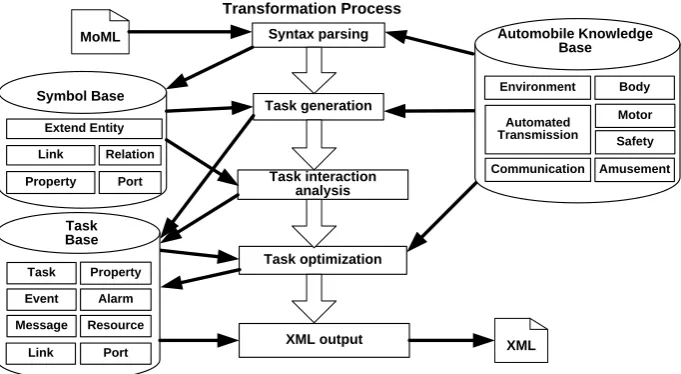
Fig. 2. The process of model transformation
In Figure 2, the transformation workflow of models is composed of five steps, i.e., syntax parsing, task generation, task interaction analysis, task optimization, and XML output. There are three databases, i.e., Symbol Base, Task Base, and Automobile Knowledge Base, and multiple tables in each database. Besides the entity name field, records of Extend Entity table in Symbols Base include the directors that entities belong to, together with the functions of entities. Records of Task table in Task Base include the functions of tasks as well as the entities it includes. Automobile Knowledge Base includes the subsystems of the automotive CPS, their functions, and the importance level of their functions according to real-time and safety-critical degree. For example, the body subsystem consists of the power window control function, the power skylight control function, the power rear-view mirror control function, and the seat adjusting function, and so on. Automobile Knowledge Base helps to partition tasks in model transformation according to their functions, and merge different tasks according to their importance levels.
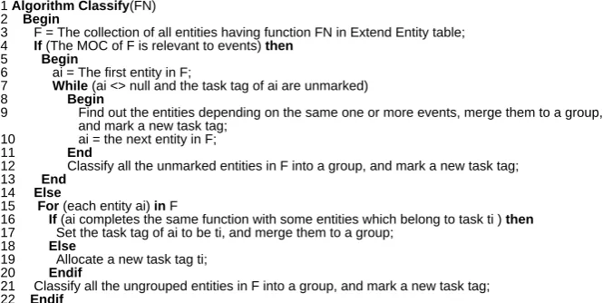
2) Task Generation: We classify the entities in Symbol Base and then create tasks, as well as find the properties and functions of each entity and output them to Task Base. We use the algorithm shown in Figure 3 to classify the entities. In Figure 3, if the MOC of F is relevant to events, Classify algorithm finds all entities depending on these events and marks the same task tag (Line 4-Line 13). Otherwise, Classify algorithm finds all entities with the same function and marks them the same task tag (Line 15-Line 22). Note that all unmarked entities and ungrouped entities are marked the same task tag (Line 12, Line 21).
1 Algorithm Classify(FN) 2 Begin
3 F = The collection of all entities having function FN in Extend Entity table; 4 If (The MOC of F is relevant to events) then
5 Begin
6 ai = The first entity in F;
7 While (ai <> null and the task tag of ai are unmarked) 8 Begin
9 Find out the entitiesdepending on the same one or more events, merge them to a group, and mark a new task tag;
10 ai = the next entity in F; 11 End
12 Classify all the unmarked entities in F into a group, and mark a new task tag; 13 End
14 Else
15 For (each entity ai) in F
16 If (ai completes the same function with some entities which belong to task ti ) then
17 Set the task tag of ai to be ti, and merge them to a group; 18 Else
19 Allocate a new task tag ti; 20 Endif
21 Classify all the ungrouped entities in F into a group, and mark a new task tag; 22 Endif
23 End
Fig. 3. Entities classifying algorithm
After classifying the entities, all entities with the same task tag are grouped into one task and saved into Task table in Symbol Base. From Property table in Symbol Base, a corresponding property table can be created for the entities in Task Base by performing the following operation:
a) If an entity is only relevant with other entities in the same task, eliminate its properties.
b) If an entity is relevant with the entities of other tasks, combine all properties of the entity as the task’s global properties and then put them into Property table in Task Base.
According to the functions of each entity in Automotive Knowledge Base, put its importance level property into Task table in Task Base.
Systems
and resources for every task in Task table and output them to corresponding tables in Symbol Base (Line 20-Line 38).
1 Algorithm Interaction() 2 Begin
3 ti = The first task in Task table; 4 While (ti <>null)
5 Begin
6 R = All relations in Relation table contained by entities pertaining to ti; 7 ri = The first relation in R;
8 While (ri<> null) 9 Begin
10 If (ri links with entities belonging to other tasks in Task table) then
11 Add a new link to Connection table in Task Base, and add the linking ports between tasks to Port table;
12 Else
13 Add a corresponding property to Property table; 14 Endif
15 ri = The next relation in R; 16 End
17 ti = The next task in Task table; 18 End
19 ti = The first task in Task table; 20 While (ti <> null)
21 Begin
22 ci = the first link associated with ti in Relation table; 23 While (ci <>null)
24 Begin
25 If (The port connected with ci transmits data) then 26 Add a message to Message table;
27 Else
28 If (The port connected with ci transmits sporadic events) then 29 Add an event to Event table;
30 Elseif (The port connected with ci transmits periodic events) 31 Add an alarm to Alarm table;
32 Endif 33 Endif
34 Search other tasks having the same property. If it succeeds, convert the property to resource and add it to Resource table;
35 ci = The next link associated with ti in Relation table ; 36 End
37 ti = The next task in Task table; 38 End
39 End
Fig.4. Task Interaction analysis algorithm
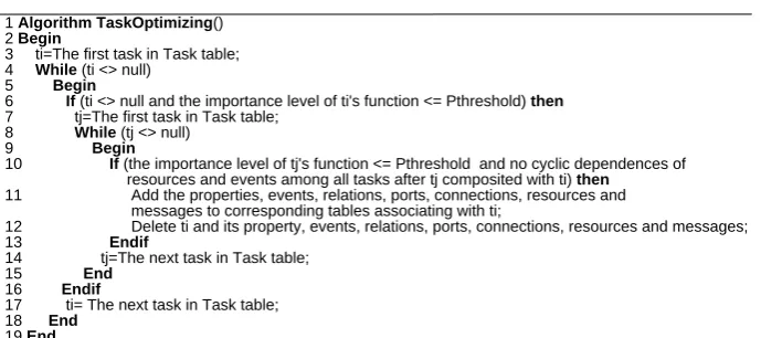
4) Task Optimization: The tasks generated are analyzed to decide whether they should be merged in order to reduce task number. The following factors should be taken into account:
a) The dependence relationship between tasks. b) The importance level of each task.
We employ the merging algorithm shown in Figure 5 to perform task optimization. In Figure 5, TaskOptimizing algorithm finds the tasks whose importance level of its function is no more than a threshold Pthreshold (which is set by developers) (Line 6), and merged them into a task in order to reduce the task number in the system (Line 11-Line 12).
1 Algorithm TaskOptimizing() 2 Begin
3 ti=The first task in Task table; 4 While (ti <> null)
5 Begin
6 If (ti <> null and the importance level of ti's function <= Pthreshold) then
7 tj=The first task in Task table; 8 While (tj <> null)
9 Begin
10 If (the importance level of tj's function <= Pthreshold and no cyclic dependences of resources and events among all tasks after tj composited with ti) then
11 Add the properties, events, relations, ports, connections, resources and messages to corresponding tables associating with ti;
12 Delete ti and its property, events, relations, ports, connections, resources and messages; 13 Endif
14 tj=The next task in Task table; 15 End
16 Endif
17 ti= The next task in Task table; 18 End
19 End
Fig. 5. Task optimizing algorithm
4.4. XML Output and Code Generation
We take out the tasks from Task Base and parse their functions, properties and relations with other tasks. As a result, An XML file is created.
Systems
algorithm can be used to analyze whether the deadlines of tasks meet and improve the energy-saving effect of software.
5.
Case Study and Analysis
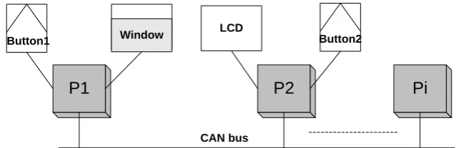
We have applied MoBDAC to the development of automotive CPS software, and achieved good effect. In this section, we demonstrate the design process presented in section 3 through a power window control system. Figure 6 shows the network topology structure of a power window control system. In Figure 6, P1 is the processor which controls the power windows, and P2 is the processor which is responsible for information display. A passenger can press Button1 to control the up or down of the power window, and a driver can also press Button2 to send messages to P1 to control the up or down of the power window. Once it changes, the position of the power window can be sent to P2 and shown in LCD.
CAN bus
P2
LCD
Pi
Button2
P1
Button1 Window
Fig. 6. The network topology structure of the power window
The power window control system is a relatively complex system with the following functions: a) manual up; b) manual down; c) automatic up; d)
automatic down; and e) obstacle-detecting. Because the up and down
messages from CAN bus is equivalent to these from Button1, we only
consider the up and down messages regardless of their sources. For
simplicity, we only consider the functions of manual up, manual down, and obstacle-detecting. Note that obstacle-detecting is a safety measure which prevents arms from being clamped when the power window is moving up. We assume the software specifications can be described as follows:
a) When a passenger pushes the up button once, the window move up for
4cm if the position of the power window is less than 40cm and there is no obstacle.
b) When a passenger pushes the down button once, the window move down for 4cm if the position of the power window is more than 0cm.
During its movement, the states of the power window are controlled by the
event of up or down. We choose FSM as its MOC and classify the states of
the power window into fully_opened, fully_closed and semi_opened.
The model of the power window built in Ptolemy II consists of three levels. The first-level model is shown in Figure 7.
Fig. 7. The first-level model of the power window
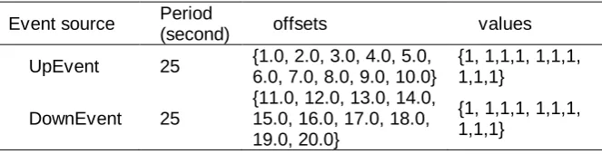
In Figure 7, there are two discrete periodical event sources (UpEvent and DownEvent), a power window model and a Timedplotter. The two discrete periodical event sources are used to generate up events, and down events respectively. Their configuration is shown in Table 1. The offsets denote the time span from the occurrences of events to the period of the events. The position of the window is output to TimedPlotter in order to observe its value.
Table 1. The configuration of event sources
Event source Period
(second) offsets values
UpEvent 25 {1.0, 2.0, 3.0, 4.0, 5.0,
6.0, 7.0, 8.0, 9.0, 10.0}
{1, 1,1,1, 1,1,1, 1,1,1}
DownEvent 25
{11.0, 12.0, 13.0, 14.0, 15.0, 16.0, 17.0, 18.0, 19.0, 20.0}
{1, 1,1,1, 1,1,1, 1,1,1}
Systems
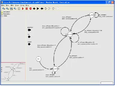
Fig. 8. The second-level model of the power window
The second-level model is a FSM denoting the state transition of the power window, as shown in Figure 8. The FSM consists of four states: init,
fully_opened, fully_closed, and semi_opened. We assume the initial state of the FSM is init. In fact, the init state is an additive state for the convenience of controling. The FSM will immediately transfers into fully_opened state from the init state when it begins to work. The end states of the FSM are
fully_opened, fully_closed, or semi_opened. The obstacle-detecting function should be implemented when an UpEvent occurs. However, whether there is an obstacle depends on physical environment is uncertain. It is difficult to simulate this uncertainty. We know obstacles need to be detected when UpEvent events occur and obstacle-detecting has the exclusive relation with UpEvent events. The Model Modifier records the following rules:
Name: Obstacle-detecting.
Relevalent Event: UpEvent.
Relationship: Exclusive.
Expression: if (it is semi_open) power-window: position = power-window: position -4; if (it is fully_opened) NO ACTION.
In the above expression, it reduces the position of the power window by 4cm when its state is semi_open; and takes no action when its state is
fully_opened.
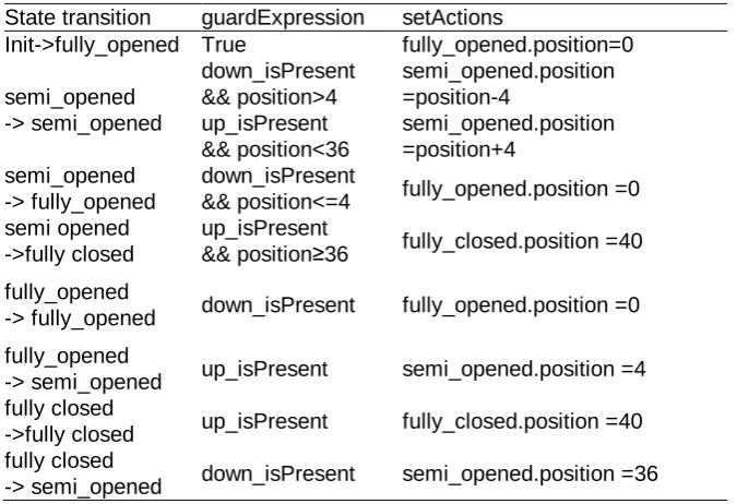
After Model Modifier records the above rules, we need not consider the obstacle-detecting function in the MPD. The relations among different states, triggering conditions (guardExpression in Ptolemy II) and triggering actions (setActions in Ptolemy II) are shown in Table 2.
In Table 2, down_isPresent denotes the occurrence of a down event;
up_isPresent denotes the occurrence of an up event; position denotes the
current position of the power window. semi_opened, fully_opened, and
fully_closed are refined into the third-level models with the same name, i.e.
the window position model. *.position denotes the position of a power window
Table 2. State transition of the power window
State transition guardExpression setActions
Init->fully_opened True fully_opened.position=0
semi_opened -> semi_opened
down_isPresent && position>4
semi_opened.position =position-4
up_isPresent && position<36
semi_opened.position =position+4
semi_opened -> fully_opened
down_isPresent
&& position<=4 fully_opened.position =0 semi opened
->fully closed
up_isPresent
&& position≥36 fully_closed.position =40 fully_opened
-> fully_opened down_isPresent fully_opened.position =0
fully_opened
-> semi_opened up_isPresent semi_opened.position =4
fully closed
->fully closed up_isPresent fully_closed.position =40
fully closed
-> semi_opened down_isPresent semi_opened.position =36
The third-level model is a model of CT denoting the position of the power window. There are three third-level models which are corresponding to the refined states of semi_opened, fully_opened, and fully_closed respectively. The three third-level models have the same structure, as shown in Figure 9.
Fig. 9. The third-level model of the power window
In Figure 10, the position at the top right is a parameter denoting the
position of the power window. The Window_Position is an expression actor. It
Systems
port. The position port is connected to TimedPlotter in order to display the position of the power window.
From the events source characteristics, we can know that the power window should move up and down in turn. The simulation result in Ptolemy II is shown in Figure 10.
Fig. 10. The simulation result of the power window
In this paper, we don’t describe all the details of the MoML file for the power window model due to space constraints, and only explain the essential parts for the model transformation.
1 <?xml version="1.0" standalone="no"?>
2 <!DOCTYPE entity PUBLIC "-//UC Berkeley//DTD MoML 1//EN" "http://ptolemy.eecs.berkeley.edu/xml/ dtd/MoML_1.dtd">
3 <entity name="windowcontrol" class="ptolemy.actor.TypedCompositeActor">
4 <property name="_createdBy" class="ptolemy.kernel.attributes.VersionAttribute" value="5.0.1"> 5 </property>
6 <property name="CT of Power Window" class="ptolemy.domains.ct.kernel.CTMixedSignalDi-rector"> 7 <property name="startTime"
… 8 </property> 9 </property>
10 <entity name="Power-Window Model" class="ptolemy.domains.fsm.modal.ModalModel"> 11 ...
12 </entity>
13 <entity name="UpEvent" class="ptolemy.domains.ct.lib.EventSource"> 14 <property name="period" class="ptolemy.data.expr.Parameter" value="25"> 15 </property>
16 <property name="offsets" class="ptolemy.data.expr.Parameter" value="{1.0,2.0,3.0,4.0,5.0, 6.0,7.0,8.0,9.0,10.0}">
17 </property>
18 <property name="values" class="ptolemy.data.expr.Parameter" value="{1, 1,1,1, 1,1,1, 1,1,1}"> 19 </property>
20 … 21 </entity> 22 ...
23 <relation name="relation3" class="ptolemy.actor.TypedIORelation"> 24 </relation>
25 ...
26 <link port="UpEvent.output" relation="relation"/> 27 ...
28 </entity>
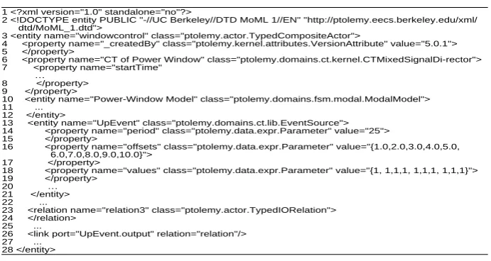
The MoML file of the first-level model is shown in Figure 11. Note that some unimportant details have been omitted by suspension points for easy to understand.
Line 1-2: They define the version and Document Type Definitions
(DTD) used in this MoML file.
Line 3-5: The file name of the MoML file is windowcontrol; the model
is a composite model (including different MOCs); the version of Ptolemy II is 5.0.1. The range of this entity is from line 3 to line 28.
Line 6-9: The name of the first-level model is ―CT of Power Window‖.
It is a CT model.
Line 10-12: They define the second-level model to descibe the state transition of the power window. Note that the second-level model uses the FSM model and its detail is omitted in line 11.
Line 13-22: They define the UpEvent entity with its periods, offsets, and values from line 13 to line 21. The DownEvent entity and the TimedPlotter entity are omitted in line 22.
Line 23-25: Relations are defined in order to represent the links
among UpEvent, DownEvent, Power-Window Model, and
TimedPlotter. Note that only one is shown, and the others are omitted.
Line 26-27: The links among UpEvent, DownEvent, Power-Window
Model, and the TimedPlotter are defined. Note that only one is shown, and the others are omitted.
The second-level model denotes the state transition of the power window, as shown in Figure 12.
1 <entity name="Power-Window Model" class="ptolemy.domains.fsm.modal.ModalModel"> 2 <port name="up" class="ptolemy.domains.fsm.modal.ModalPort">
3 <property name="input"/> 4 </port>
5 ...
6 <entity name="fully_opened" class="ptolemy.domains.fsm.kernel.State"> 7 ...
8 </entity> 9 ...
10 <relation name="relation6" class="ptolemy.domains.fsm.kernel.Transition"> 11 <property name="guardExpression" class="ptolemy.kernel.util.StringAttribute"
value="up_isPresent && position>=36"> 12 </property>
13 <property name="setActions" class="ptolemy.domains.fsm.kernel.CommitActionsAttribute" value="fully_closed.position=40">
14 </property> 15 ... 16 </relation> 17 ...
18 <link port="fully_opened.incomingPort" relation="relation8"/> 19 ...
20 <entity name="fully_opened" class="ptolemy.domains.fsm.modal.Refinement"> 21 ...
22 </entity> 23 ... 24 </entity>
Fig. 12. The second-level model stored in MoML file
Line 1: The name of the model is Power-Window Model. It is a FSM
Systems Line 2-5: They define an input port, i.e. up port, from line 2 to line 4.
Other ports and their properties are omitted in Line 5.
Line 6-9: They define an entity named fully_opened from line 6 to line
8 to denote a state of the FSM in the second-level model. Other entities and their properties are omitted in line 9.
Line 10-17: They define a state transition with its triggering condition (guardExpression) and corresponding actions (setActions) from line 10 to line 16. Other state transition, triggering condition and corresponding actions are omitted in line 17.
Line 18-19: They define all the links used in the second-level model.
Line 20-23: they denote a third-level model refined from the
fully_opened states from line 20 to line 22. Other third-level models from the refinement of fully_closed and semi_opened are omitted in line 23.
The third-level model denotes the position of the power window, as shown in Figure 13.
1 <entity name="fully_opened" class="ptolemy.domains.fsm.modal.Refinement"> 2 <property name="CT for Position"
class="ptolemy.domains.ct.kernel.CTEmbeddedDirector"> 3 ...
4 </property>
5 <port name="up" class="ptolemy.domains.fsm.modal.RefinementPort"> 6 <property name="input"/>
7 ... 8 </port> 9 ...
10 <entity name="Window_Position" class="ptolemy.actor.lib.Expression"> 11 <property name="expression" class="ptolemy.kernel.util.StringAttribute"
value="position"> 12 </property> 13 ... 14 </entity>
15 <relation name="relation" class="ptolemy.actor.TypedIORelation"> 16 </relation>
17 <link port="position" relation="relation"/>
18 <link port="Window_Position.output" relation="relation"/> 19 </entity>
Fig. 13. The third-level model stored in MoML file
Line 1: The name of the model is fully_opened. It is a refinement of the FSM model.
Line 2-4: The third-level model is a CT model.
Line 5-9: The up port and its properties are defined from line 5 to line
8. The other two ports, the down port and the position port are omitted in line 9.
Line 10-14: They define the expression entity in the third level and its
properties, ports, relations and links.
Line 15-18: They define the relations and links used in the third-level
model.
the second-level model (power window model) and the third-level models (power window position model) before performing model transformation. In order to recognize the type of the input and output signals, we add signalType
parameters to the up port and the down port with the values of ―DISCRETE‖,
and a signalType parameter to the position port with the value of
―CONTINUOUS‖. The process of model transformation consists of five steps. First, parse the MoML file of the power window. Although directors are entities, they are not viewed as common entities because they are only used to denote MOC. There are four entities in the power window model, init, semi_opened, fully_opened, and fully_closed. From the Automobile Knowledge Base, their functions are found and put into Extend Entity table, as shown in Table 3. The properties, relations, ports and links are also parsed. Some properties are not needed, such as the size, position, color, etc. They are not included in Property table.
Table 3. Functions of entities
Entity name MOC Function
init FSM Body_Window
semi_opened FSM Body_Window
fully_opened FSM Body_Window
fully_closed FSM Body_Window
Second, generate tasks. Because entities of semi_opened, fully_opened, and fully_closed have the same function (Body_Window) and depend on the
up event and down event, they are grouped into a task named task1. The entity init is also included into task1 because it has the same function with other entities in task1. The other three entities in the third-level model are classified into task2.
Third, analyze the interaction among tasks. The state transition information of task1 is stored in Property table. The position property is stored in Property table of task2. The up event and down event, including the triggering condition and state transition, are stored in Event table of task1. The up port and down port are stored in Port table of task2. The position port is stored in Port table of task2. Because task2 controls the position of the power window, a resource, res1, is created and put into Resource table.
Fourth, optimize tasks. In the Automobile Knowledge Base, the functions that task1 and task2 perform are not safety-critical, and have lower priority.
task1 and task2 are incorporated into one task, task3. Their properties, ports, and events are incorporated into a new task. task1 and task2 are removed from Task table. The priority is an important property for a task. We assign the priority levels of tasks according to the importance level of their functions. Fifth, generate the XML file. task3 are taken out from Task Base. It waits for two events. task3’s running information can be generated according to the
Systems
Fig. 14. Models in AECPSDesigner
The pseudo-codes of the generated codes are shown in Figure 15. In Figure 15, task3 first initializes the position and state of the power window (Line 2-Line 3), and then waits and processes input event (Line 4-Line 28). Once receiving an input event, task3 obtains a resource in order to access the power window (Line 6), and then changes the position and state of the power window according to the rulers in Table 2 (Line 7-Line 26). Note that the obstacle-detecting is implemented in Line 9-Line 10 and Line 20-Line 23. After that, task3 updates the state of the power window, sends its position to P2 by CAN bus (Line 25), and release the resource (Line 27).
From the development process of the power window, we can know MoBDAC covers the whole development workflow of software. By separating
function requirements, non-functional requirements, and physical
1 TASK(Task){
2 Set initial position of the power window to be zero; 3 Set initial state of the power window to be fully_opened; 4 While (true){
5 Wait for an event;
6 Obtain the resource of the power window; 7 if (The state is fully_opened) {
8 if (The event is an up event) 9 if (No obstacle is detected)
10 Set the position of the power window to be 4. 11 }
12 else if (The state is fully_closed) { 13 if (The event is a down event)
14 Set the position of the power window to be 4. 15 }
16 else {
17 if (The event is a down event)
18 Decrease the position of the power window by 4. 19 else if (The event is a up event)
20 if (No obstacle is detected)
21 Increase the position of the power window by 4. 22 else
23 Decrease the position of the power window by 4. 24 }
25 Send the position of the power window to CAN bus. 26 Update the state of the power window.
27 Release the resource of the power window; 28 }
29 TerminateTask(); }
Fig. 15. Codes generated by AECPSDesigner
6.
Conclusions
Aiming at the development of automotive CPS software, we present a model-based development method under operating systems compatible with OSEK/VDX specification. This method increases development efficiency by automatic tools, and can verify the correctness of function requirements, non-functional requirements, and integrate the interaction with physical environment. The future work is to integrate more analysis methods for non-functional requirements and verify the interaction with physical environment in MIP.
Acknowledgment. This work has been supported by the Pre-research Scheme of
Systems
References
1. Sha, L., Gopalakrishnan, S., Liu, X., Wang, Q.: Cyber-Physical Systems: A New Frontier. In Proceedings of the 2008 IEEE International Conference on Sensor Networks, Ubiquitous, and Trustworthy Computing (SUTC 2008), 1–9. (2008) 2. Shih, E., Bahl, P., Sinclair, M. J.: Wake on Wireless: An Event Driven Energy
Saving Strategy for Battery Operated Devices. In Proceedings of the 8th Annual International Conference on Mobile Computing and Networking (MobiCom 2002), 160–171. (2002)
3. Yoerger, D. R., Jakuba, M., Bradley, A. M., Bingham, B.: Techniques for Deep Sea Near Bottom Survey Using an Autonomous Underwater Vehicle. Journal of Robotics Research, Vol. 26, No. 1, 41–54. (2007)
4. Lee, E. A.: Cyber Physical Systems: Design Challenges. International Symposium on Oriented Real-Time Distributed Computing (ISORC’08), 363-369. (2008)
5. Selic, B., Gullekson, G., Ward, P.: Real-Time Object-Oriented Modeling. John Wiley & Sons, New York, NY. (1994)
6. Selic, B., Rumbaugh, J.: Using UML for modeling complex real-time systems. (1998). [Online]. Available: http://www.objectime.com/uml.
7. The SDL Forum website. (2005). [Online]. Available: http://www.sdl-forum.org. 8. Sztipanovits, J., Karsai, G.: Model-integrated Computing. IEEE Computer, Vol.
30, No. 4, 110-112. (1997)
9. Lee, E. A.: Overview of the Ptolemy Project. (2003). [Online]. Available: http://Ptolemy.eecs.berkeley.edu/publications/papers/03/overview/.
10. MoBIES Automotive Open Experimental Platform. (2003). [Online]. Available: http://vehicle.me.berkeley.edu/mobies/.
11. Magureanu, G., Gavrilescu, M., Pescaru, D., Doboli, A.: Towards UML Modeling of Cyber-Physical Systems: A Case Study for Gas Distribution, In Proceedings of the 8th International Symposium on Intelligent Systems and Informatics (SISY 2010), 471–476. (2010)
12. Bhatia, G., Lakshmanan, K., Rajkumar, R.; An End-to-End Integration Framework for Automotive Cyber-Physical Systems Using SysWeaver. In Proceedings of the 1st Analytic Virtual Integration of Cyber-Physical Systems Workshop (AVICPS 2010). (2010)
13. OSEK/VDX Binding Specification Version 1.4.1. (2003). [Online]. Available: http://www.osek-vdx.org/mirror/oil241.pdf.
14. Ledeczi, A., Maroti, M., Bakay, A., et al.: The Generic Modeling Environment. In Proceedings of the IEEE Workshop on Intelligent Signal Processing (WISP 2001). (2001)
15. The MathWorks, Inc. (2011). [Online]. Available: http://www.mathworks.com/. 16. Metacase company. (2011). [Online]. Available: http://www.metacase.com/. 17. DOME Users’ Guide. (2011). [Online]. Available: http://www.htc.honeywell.com
/dome/support.htm#documentation.
18. Telelogic inc. (2011). [Online]. Available: http://modeling.telelogic.com/index.cfm. 19. Woo, H., Yi, J., Browne, J. C., et al.: Design and Development Methodology for Resilient Cyber-Physical Systems. In Proceedings of the 28th International Conference on Distributed Computing Systems Workshops (ICDCS Workshops 2008), 525-528. (2008)
8th IEEE International Conference on Dependable, Autonomic and Secure Computing (DASC 2009), 690-695. (2009)
21. Ma, L., Yuan, T., Xia, F., et al.: A High-confidence Cyber-Physical Alarm System: Design and Implementation. In Proceedings of 2010 IEEE/ACM International Conference on Green Computing and Communications (GreenCom) & International Conference on Cyber, Physical and Social Computing (CPSCom), 516-520. (2010)
22. Tsai, J. J. P., Li, B., Liu, A.: Modeling and Parallel Evaluation of Non-Functional Requirements Using FRORL Requirements Language. In Proceedings of the 8th Annual International Computer Software and Applications Conference (COMPSAC 1994), 11-16. (1994)
23. Chung, L., Nixon, B. A., Yu, E., Mylopoulos J.: Non-functional requirements in Software Engineering. Kluwer Academic Publishers. (1999)
24. Fidge, C.J., Lister, A. M.: The Challenges of Non-Functional Computing Requirements. In Proceedings of the 7th Australian Software Engineering Conference (ASWEC 93). (1993)
25. Lee, E. A.: Embedded Software. Advances in Computers, Vol. 56, 56-97. (2002) 26. Niz, D. de, Rajkumar, R.: Model-based Embedded Real-time Software
Development. (2003). [Online]. Available: http: //www.cse.wust1.edu/~cdgill /RTASO3/published/TimeWeaverPosition.pdf.
27. CodeWarrior Development Tools. (2011). [Online]. Available: http://www.freescale. com/webapp/sps/site/homepage.jsp?code=CW_HOME. 28. Brooks, C., Lee, E. A., Liu, X., Neuendorffer, S., Zhao, Y., Zheng, H.:
Heterogeneous Concurrent Modeling and Design in Java (volume 1: Introduction to Ptolemy II). University of California, Technical Report UCB/ERL M05/21. (2005)
29. Gao, Z., Wu, Z., Lin, M.: Energy-Efficient Fixed-Priority Scheduling for Periodic Real-Time Tasks with Multi-Priority Subtasks. In Proceedings of the 2007 International Conference on Embedded Software and System (ICESS 2007), LNCS, Vol. 4523, 572-583. (2007)
30. Gao, Z., Wu, Z., Li, H.: Implementation Synthesis of Embedded Software under Operating Systems Supporting the Hybrid Scheduling Model. In Proceedings of the 2006 IFIP International Conference on Embedded and Ubiquitous Computing (EUC 2006), LNCS, Vol. 4096, 426-436. (2006)
31. Gao, Z., Wu, Z.: Implementation Synthesis of Embedded Software under the Group-Based Scheduling Model. In Proceedings of the 12th IEEE International Conference on Embedded and Real-Time Computing Systems and Applications (RTCSA 2006), 190-196. (2006)
32. Wilhelm, R., Engblom, J., Ermedahl, A., et.al.: The Worst-Case Execution-Time Problem—Overview of Methods and Survey of Tools. ACM Transactions on Embedded Computing Systems (TECS), Vol. 7, No. 3, 36:1-36:53. (2008)
Systems
Haixia Xia received the Ph.D. degree from Zhejiang University, Hangzhou, China in 2007. She is a teacher in the College of Informatics & Electronics, Zhejiang Sci-Tech University, Hangzhou, China. Her current research interests are pervasive computing and motor systems.
Guojun Dai received the Ph.D. degree from Zhejiang University, Hangzhou, China in 1998. He is a professor in the College of Computer Science, Hangzhou Dianzi University, Hangzhou, China. His current research interests are pervasive computing and intelligent embedded systems.