International Journal of Mechanical & Mechatronics Engineering IJMME-IJENS Vol:14 No:06 22
Development of a Dedicated CNC Controller for
Wheel flow Forming Machine and Experimental
Performance Evaluations
Jong-Min Kim
1, So Young Hwang
2, Dong-Soo Kim
3, In-Hugh Choi
3, Naksoo Kim
2and Cheol-soo Lee
21 Sogang Institute of Advanced Technology (SIAT), Sogang University, Seoul, 121-742, South Korea 2 Department of Mechanical Engineering, Sogang University, Seoul, 121-742, South Korea
3 CSCAM. Co. ltd., Gwangju, 506-500, Korea
Corresponding Author: Cheol-soo Lee [email protected]
Abstract-- This research describes the performance data of the aluminum automobile wheel manufactured by wheel flow forming machine. The performance is examined after designing and operating the CNC controller which is customized for the wheel forming machine. In general, the existing wheel flow-forming machine simultaneously controls the 3 rollers and axis, which results in the degradation of the quality of the product due to syncing to the slowest one and slowing down in its processing speed.
In order to solve this problem, multi-channel CNC controller has been developed and is able to independently control each individual roller and axis in short cycles. In order to practice the multi-channel CNC, the mutual communication of the fundamental structure of the CNC controller utilizes sync signal and each thread is applied with the sharing memory data sync method through the EtherCAT communication.
When producing wheel forming by utilizing the customized CNC controller, it has been found that there had been a great improvement in processing time (productivity) and degree of precision, in comparison to the existing wheel flow-forming machine.
1. INTRODUCTION
Over the recent years, fuel saving, energy efficiency, and pollution control in automobile sector have been discussed as global issues. Particularly, the more recent studies have increasingly been focused on lighter vehicle design with enhanced fuel efficiency. Evidences have shown that reducing 1 kg of the lower part of a vehicle frame results in 10-15 kg lighter car in total. One of the most efficient ways to reduce the weight of the lower part is developing lighter wheels.
Aluminum is the most common material used for alloy wheel due to its good fuel economy, light weight and shock absorption capacity as well as beautiful appearance. Especially, aluminum is about one-third the density of steel, which is optimal in terms of light weight. Manufacturing methods of aluminum wheels include low-pressure casting, cold forging and hot forging, and liquid forging. Considering the processing or forming time, aluminum wheels are generally produced first by low-pressure casting, then, by hot forging. However, as the forging process requires a pressing device to exert sufficient pressure on aluminum and shape it into wheels, spinning, which involves spin-forming, or flow-forming are commonly used rather than forging.
In order to improve the performance and lightweight of aluminum wheels mentioned above , flow-forming process is additionally applied to the low-pressure cast wheels. These aluminum wheels have better mechanical properties and 10-18% lighter in weight, leading to reduction in material and energy. Increased strength also enhances driving stability of vehicles. The method enables 12% material saving compared to the traditionally cast wheels, which enables production cost saving and resource efficiency. Cutting carbon pollution is also an additional benefit of flow-forming process.
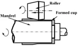
As seen in Fig. 1, flow-forming is one of the metal forming techniques that applies pressure on the rotating mandrel using rollers and produces intended wheel products.
The material is formed to flow in the axial directions. That is, the rollers work as tools in cutting process. It means that the rollers continue spinning to press against the material, ensuring lower thickness and increased mechanical strength. In addition, it needs to make sure the speed of spindle is synchronized with that of the rollers.
Previous studies on flow-forming technique have been focused on forming process itself or material properties after forming[1]. For example, Wong investigated the following fields and compared the differences between theories and experiment results: product forming process; force and deformation during forming process; roller design; cutting force and surface roughness by material[2]. Moreover, the author researched the differences in flow forming ability shown by a range of thickness by fabricating a cup-like structure from a flat disk with flow-forming process. In the research, 3-dimensional FE analysis was followed while experiment was conducted to validate the analysis[2]. Haghshena specifically conducted experiment and analyzed data on the average yield stress and surface structure of Al 5052 and Al 6061 when thickness is reduced by flow-forming process[4].
International Journal of Mechanical & Mechatronics Engineering IJMME-IJENS Vol:14 No:06 23 rollers.
The first roller begins rough cutting to make similar shapes. Fast, deep, and rough processing is carried out in this stage. The second roller trims the rough face and finishes it close to the accurate size. Finally, the third roller precisely finishes the surface to produce the intended size. Those stages of three rollers can be unified with controlled time gap in order to boost productivity. However, the independent control of three rollers is required to ensure consistent processing condition where three rollers are simultaneously involved in forming with different tip speeds. Therefore, multi-channel CNC controller is necessary in independently controlling the three rollers and the spindle.
This study explores the design of a dedicated CNC controller for wheel flow-forming machine and experimental performance evaluation to obtain increased productivity. In Section 2, the software design of CNC controller for implementation of a multi-channel model is discussed. In order to practice the multi-channel CNC, the mutual communication of the fundamental structure of the CNC controller utilizes sync signal and each thread is applied with the memory data sync method through the EtherCAT communication. Providing comparison with traditional wheel flow-forming machine, Section 3 shows improvement in processing time (i.e. productivity), surface accuracy, surface roughness, and durability. Finally, Section 4 describes conclusions of the study.
Fig. 1. Schematic overview of flow-forming process
Fig. 2. Wheel flow-forming machine and three rollers
Fig. 3. Diagram of multi-channel CNC controller
2. DEVELOPMENT OF CNC CONTROLLER In general, the existing wheel flow-forming machine simultaneously controls the 3 rollers and axis, which results in the degradation of the quality of the product due to syncing to the slowest one and slowing down in its processing speed. In order to solve this problem, multi-channel CNC controller has been developed and is able to independently control each individual roller and axis in short cycles.
Fig. 3 is a diagram of multi-channel CNC controller for wheel flow-forming machine. The EtherCAT-based high speed communication module and each axis are subject to independent control by Kernel manager while the system is comprised of threads such as IRP, IRO, POS, and PLC. Other features include sync codes that enable channels to mutually transmit signals state data sync through memory sharing of the self-developed CNC program that implements the control logic; interoperation with peripheral devices; and the user interface design.
2.1 EtherCAT based high speed communication module For the machines that require constant and large amount of load, a hydraulic servo control system is more appropriate than an electric servo control. As it applies to the wheel flow-forming machine, a high precision hydraulic serve control was designed by adopting the EtherCAT-based communication, which demonstrates outstanding update speed. EtherCAT is an open and industrial Ethernet technology, as part of an International Standard. Also, EtherCAT, which supports Line, Ring, Drop Line, and other network topologies, provides a remarkably flexible communication network. The EtherCAT-based communication module is shown in Fig. 4.
2.2 Synchronization code for inter channel sync
The CNC channel function is intended to remove set-up errors and unnecessary time in changing machine tools to perform different processes. It is known to improve productivity by simultaneously working with several CNC turrets and spindles. The unified process can also save some space to be used for installation of machines.
International Journal of Mechanical & Mechatronics Engineering IJMME-IJENS Vol:14 No:06 24 with the path and synchronized. Without the channel function,
three tools (wheels) work from one NC data, causing unbalanced stress distribution with a different forming motion. In addition, inter channel communication must be materialized in order to set the timing of motion sync between channels. M code, which is intended for the purpose, sends mutual sync signal as seen in Fig. 5.
2.3 Data sync through memory sharing and software Processing under one system generally requires synchronization of state information except major processing parameters. In line with it, the wheel flow-forming system brought overlapped state data together through memory sharing for faster processing of multi-channel CNC control, saving multiple monitoring times. It ultimately leads to more efficient processing of the key parameters related to practical work.
Fig. 5 outlines memory sharing for data sync and communication model. It has a structure that processes three units of NC data at a time with one HMI. The system carries out analysis of NC data, interpolation control, and position control independently in each channel. If a certain channel finds a pre-determined stand-by M code, the channel waits for the same M code commanded in another channel and execute the next block to meet the processing timing between channels.
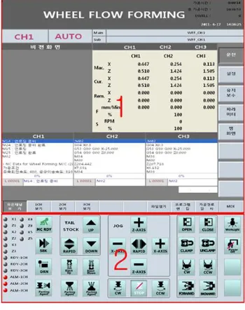
Fig. 6 is customized wheel flow-forming software. As discussed in Section 2.2, the multi-channel CNC controller independently drives each channel and controls it with sync codes. It presents coordinates of wheel position, commanded NC data, and a path of wheel control point in one HMI screen. Operation panel displays the selected channel while buttons of the corresponding channel are set to be operated upon change in channel.
Fig. 4 Communication module model based on EtherCAT
Fig. 5. Concept of multi-channel synchronization
Fig. 6. Customized wheel flow-forming software
3. PERFOMANCE EVALUATION
Fig.7 is a picture of an aluminum wheel forming machine equipped with multi-channel CNC control.
The equipment is operated by components such as hydraulic servo cylinder, linear scale, hydraulic servo amp, and so on. Evaluation criteria can include formability, productivity, durability, and others.
3.1 Productivity
Wheel processing time for a single-channel and a multi-channel is compared in Fig. 8. For single multi-channel, if several rollers are controlled at a time, the speed is synchronized to the axis with longest distance. As a result, the roller speed remains inconsistent and the total forming time increased compared to the commanded speed. On the other hand, a multi-channel flow-forming machine maintains the commanded speed because each channel is given a independent speed control. Consequently wheel productivity per hour increases.
3.2 Surface roughness
International Journal of Mechanical & Mechatronics Engineering IJMME-IJENS Vol:14 No:06 25
Fig. 7. Multi-channel wheel flow-forming machine
single-channel CNC Multi-channel CNC
Wheel
m
achining
tim
e
[sec
]
30 32 34 36 38 40 42 44 46
Fig. 8. machining time for single and multi-channel CNC
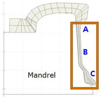
Fig. 9. Surface roughness measurement section
single-channel CNC Multi-channel CNC
Su
rfac
e
ro
u
g
h
n
e
s
s
[
m]
0 2 4 6 8 10
Section A Section B Section C
Fig. 10. Single and multi-channel machined Surface roughness (um)
3.3 Durability
Durability and vibration of equipment are among the significant factors for users. The vibration determines the level of precision, which is directly related to competitiveness. In addition, a work condition associated with noise should be considered for practical use. The noise levels of single-channel and multi-single-channel are compared in Fig. 11 and the result reveals that the multi-channel flow-forming machine produces less noise. It is attributable to the constant load on the rollers with the same speed controlled by the multi-channel model.
single-channel CNC Multi-channel CNC
Noise [
dB
]
0 20 40 60 80 100
Fig. 11. Comparison single-channel and multi-channel system
- noise(dB)
4. CONCLUSIONS
The study investigated the development of the multi-channel wheel flow-forming machine and analyzed its experimental performance. The multi-channel model is known to be an original concept that addresses the shortcomings of a single-channel wheel flow-forming machine.
International Journal of Mechanical & Mechatronics Engineering IJMME-IJENS Vol:14 No:06 26 channel machine decreased processing time by 16% per
product compared to the existing single channel. In terms of productivity calculated to unit time, additional 15 aluminum wheels can be made with multi-channel. Surface roughness was also improved up to 40 % while improvement of 20 to 30% was observed in each area. On top of it, the experiment found the roughness distribution per product was stabilized. 20% improvement in noise and vibration indicates that overall durability is predicted to increase as well as production stability.
ACKNOWLEDGEMENT
This work was supported by the Technology Innovation Program funded by the Ministry of Knowledge Economy Korea No.10043127
REFERENCES
[1] Groche, P., Fritsche, D., 2006, "Application and modelling of flow forming manufacturing processes for internally geared wheels", Int. J. of Machine Tools and Manufacture, Vol. 46, Issue 11, pp. 1261-1265
[2] Wong, C.C., Dean, T. A., Lin, J., 2003, "A review of spinning, shear forming and flow forming processes", Int. J. of Machine Tools and Manufacture, Vol. 43, Issue 14, pp. 1419-1435 [3] Wong, C.C., Danno, A., Tong, K.K., Yong, M. S., 2008, "Cold
rotary forming of thin-wall component from flat-disc blank", J. of Materials Processing Technology, Vol. 208, Issue 1-3, pp. 53-62 [4] Haghshenas, M., Wood, J.T., Klassen, R.J., 2012, "Investigation of