Abstract—The current analytical methods of Dynamic Fault
Tree (DFT) are very complex and there is problem of state space explosion. At the same time, the current simulation methods also have several shortcomings which prevent the application of these models, including difficult to construct the model, discommodious to convert between simulation model and DFT model. In order to solve these problems, the formal description of DFT is put forward, which can express the DFT normatively and clearly. Based on the formal model, the DFT element is described by parameters, and then the general simulation model of DFT is constructed by using CPN TOOLS, and this model can largely reduce the workload of model conversion. Finally the case shows that the method is correct and useful.
Index Terms—Reliability, dynamic fault tree, colored petri nets, formal model, general simulation model.
I. INTRODUCTION
The logic gates involved in traditional fault tree include “AND”, “OR”, “NOT”, etc., which are normally called static gates. Considering the interdependence of various basic events within the process of time change [1], it is necessary to introduce several dynamic logic gates that can reflect the dynamic characteristics of system (sequence activities) to make fault tree better deal with special complex characteristics, including Priority-AND gate (PAND), Functional Dependency gate (FDEP), Sequence Enforcing gate (SEQ), Cold Spare gate (CSP), Warm Spare gate (WSP) and Hot Spare gate (HSP), etc. The fault tree including dynamic logic gate is called dynamic fault tree (DFT). Through introducing dynamic logic gate, the reliability and safety of dynamic system can be modeled and analyzed [2].
For solution of DFT, the combination of BDD and Markov proposed by Dugan [3] in the University of Virginia is currently employed. The DFT is broken down into static sub-tree and dynamic sub-tree. Static sub-tree is converted into BDD for processing while dynamic sub-tree is converted into Markov chain for solution. Among simulation methods, Volovoi [4] put forward the reliable Petri net modeling of system, and claimed that Petri net can better solve the problem of state space explosion in Markov chain. However, fault tree is modeled using Petri net, which normally follows the corresponding conversion rules. Thus, the model varies along with fault tree.
Even though every behavior of DFT can be modeled theoretically by taking such methods as Markov chain,
Binary Decision Diagram (BDD), Colored Petri Nets (CPN), Monte Carlo simulation, etc., but these methods have some major defects as follows [5]:
1) Lack of grammatical and semantic formal model, which may cause erroneous motion or understanding under some circumstances;
2) Lack of model analysis, which may easily result in the problem of state space explosion along with the increase of DFT scale since it is normally converted into Markov chain at first;
3) Lack of modularized modeling, which is a fatal defect to these models, “Distance from model builder” or “degree of user friendliness”. The grammatical elements in model are not the corresponding parts in system model [6]. In Reference [7], CPN TOOLS was applied to establish a general reliability model for Phased Mission System (PMS) fault tree, so as to maintain the structural stability of model and study the mission reliability model for different phases and systems. After generalizing relevant achievements, this paper firstly presents a formal description of constructing DFT and obtains the data structure of DFT model. On this basis, CPN TOOLS is employed to construct a general simulation model. After parameterization, DFT description is taken as an input into CPN simulation model to realize the rapid conversion between models.
II. DFT AND ITS FORMAL MODEL
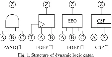
DFT contains at least one dynamic logic gate. The common dynamic logic gates are presented in Fig. 1. With logic gate, event and connecting arc, the causal relations of events in a system can be described to build the DFT model for the system.
A B C
Z
PAND门
T A B
Z
FDEP门
SEQ
A B C
FDEP门
Z
CSP
A S
Z
CSP门
Fig. 1. Structure of dynamic logic gates.
There are already lots of formal descriptions about DFT. In this paper, the description is given based on Reference [8].
For formal model of DFT, the description of DFT should be firstly simplified. DFT contains only bottom event (which is called basic event herein) and logic gates, and the intermediate events and top events in traditional fault tree match with the corresponding logic gates, so they can be represented by logic gates.
Research of the Formal Model and Simulation Based on
CPN of Dynamic Fault Tree
Chun Huiyang and Lu Yao
Before building the formal model of DFT, several basic symbols are described as follows:
1) Primitive set
: In DFT, basic event or logic gate is a primitive, so they can be described through the type of primitive, input quantity and other possible parameters. All primitives in DFT form a set .2) A setX is given and *
X is defined to the set of all sequences in the setX.
3) If a sequencexX*,xis defined to be the length of the
1) (BE,0, , ) describes basic event. There is not input. Work fault rate and non-work fault rate are
andrespectively.
2) (OR n, ), (AND n, )and (PAND n, )describe the OR gate, AND gate and PAND gate of n inputs.
3) (VOT n k, , ) stands for K/N gate with n inputs and threshold of k.
4) (SPARE n, )stands for SPARE gate with 1 work and n-1 spare parts. Normally, the first input of SPARE gate is work part.
5) (SEQ n, )stands for SEQUENCE gate with n inputs. 6) (FDEP n, )stands for FDEP gate with 1 triggered input
event and n-1 dependent input event. Conventionally, the first input is taken as trigger event.
Given a primitive
e
, we taketype e( ) as the first parameter in the primitivee
, andarity e( )as the second parameter in the primitivee
.Each vertex
v
in dynamic fault tree can be presented as a DFT primitive l v( ) . A line from vertexv
to vertexw
means that the output of the primitive ( )l v is the input of the primitive ( )l w . With regard to the input for some gate, it is necessary to consider the sequence of inputs (e.g. SEQ gate and PAND gate, etc.), so the inputs of the vertexv
are presented bypreds v( ).Definition 2: A dynamic fault tree is a quadruple
( , , )
quardruple D V preds l , in which: 1) Vis a vertex set;
2) l V: is a marking function, assigning the primitive of DFT to each vertex;
3) *
:
preds VV assigns the input function to each vertex. The set of connecting arcs E in DFT can be represented as follows:
2
{( , ) | ,
E v w V i v(preds w( )) }i . In which, the vertex
v
is the precursor of the vertexw
. To be simple, we presenttype v( )astype l v( ( )) and arity v( )asarity l v( ( )). A well-constructed DFT should satisfy the following requirements:1) ( , )V E is a directed acyclic graph;
2) All inputs in DFT must point at each vertex inD, that is, to all v V , arity v( ) | preds v( ) |;
3) There is only a top output element in D;
4) The first input of SPARE gate cannot be taken as the input of other SPARE gates. If v(preds w( ))1(preds w( ))1,
andtype w( ) type w( )SPARE, ww;
5) The input of SPARE gate must be basic event. If ( )
type w SPARE , type preds w(( ( )) )i = BE to all
1 i preds w( );
6) The dependent input of FDEP must be basic event. If ( )
type w FDEP
, type preds w(( ( )) )i = BE to all
2 i preds w( ) ;
7) The output of the same gate cannot be taken as the input of the same gate for several times. To all1i j, preds w( ) , if (preds w( ))i =(preds w( ))j ,
i j. A. Final Stage
When you submit your final version, after your paper has been accepted, prepare it in two-column format, including figures and tables.
B. Figures
As said, to insert images in Word, position the cursor at the insertion point and either use Insert | Picture | From File or copy the image to the Windows clipboard and then Edit | Paste Special | Picture (with “Float over text” unchecked).
The authors of the accepted manuscripts will be given a copyright form and the form should accompany your final submission.
III. FORMAL MODEL BASED ON CPN OF DFT A. CPN and CPN Tools
CPN is an expansion of traditional Petri net, which classifies or analyzes the tokens in the net system to reduce the basic elements of net system, so as to reduce the scale of Petri net system. The hierarchy of CPN guarantees that the minor change of simulated system will not change the structure of model entirely. The formal model of CPN is defined in Reference [9].
CPN TOOLS is a tool developed by Aarhus University in Denmark to edit, simulate and analyze colored Petri net. A user may use CPN TOOLS to module and simulate any parallel system and analyze its characteristics. SML language is employed to expand the model, so that it acquires very powerful and convenient ability to describe all kinds of systems.
CPN ML is expanded and generated based on standard ML (SML) language, and mainly applied in three aspects: 1) the descriptive words in CPN, including initial marking, arc expression and judging condition; 2) the internal semantic when enabling and triggering in change of computation; 3) the code segment of change. Like other programming language, CPN ML has own string, data type, variable and function, etc. This paper makes use of these advantages of CPN TOOLS to construct the general simulation platform of sequence, and ( )x iis the ithelement in the sequence
x
.In DFT, basic event and logic gate can be used to indicate a vertex in the diagram, so the whole DFT is a directed acyclic graph. According to the characteristics of basic event and logic gate, different primitives can be categorized in terms of type and input quantity.
DFT and realize the rapid modeling of DFT simulation model.
B. CPN Description of DFT Primitive
This section mainly describes the expression of DFT primitive in CPN model. In the CPN model, DFT parameters are converted into input and output signals. In the previous section, DFT primitives include basic event and gate. The types of gate include: bottom event (BE), and gate (AND), or gate (OR), priority and gate (PAND), sequence gate (SEQ), functional dependency gate (FDEP), K/N gate (VOT) and spare gate (SPARE). The states of bottom event include work
(WORK), fault (FAULT), hot spare (HSPARE), cold spare (CSPARE) and functional dependency gate dependent event (FDEPR). The states of gate include work and fault.
The formal description of basic event is (BE,0, , ) . In the CPN model, serial number and state variable are added to distinguish different basic events and reserve states. Therefore, the color set of basic events in CPN model is as follows:
(serial number, type, input (list), state, work fault rate, reserve fault rate)
E1
R
E3 EList
E2
(no_e,t,in1,s,rand1,rand2)
1`discrete(0,10000) INT Event
1`discrete(0,10000)
i
if (s=HSPARE andalso rand2>i) orelse (s<>HSPARE andalso rand1>i) then 1`(no_e,t,in1,FAULT,rand1,rand2) else empty
if (s=HSPARE andalso rand2<=i) orelse (s<>HSPARE andalso rand1<=i) then 1`(no_e,t,in1,s,rand1,rand2) else empty
event Event
Event fel
ins fel (#1 event)
colset State = with WORK | FAULT | CSPARE | HSPARE | FDEPR; colset Rate = INT; colset SeqN = INT; colset Input = list SeqN; colset Event = product
SeqN*Type*Input*State*Rate*Rate timed;
colset EventList = list Event; colset FEventList = list SeqN; var no_e,no_e1:SeqN; var in1,in2:Input; var event:Event; var fel,fel2,sel:FEventList; var inp:Input;
var i,r,n,j:INT;
FEventList
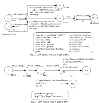
Fig. 2. CPN model of basic event in DFT.
D D1
FList
DList
Door Door
(no_e1,t,inp,s) (no_e1,t,inp,s) (no_e1,t,inp,s)
fel
if (length(intersect fel inp)>=i) then ins fel no_e1
else fel
if (length(intersect fel inp)>=i) then 1`(no_e1,t,inp,FAULT)
else
1`(no_e1,t,inp,s)
colset Door = product SeqN*Type*Input*State timed; [t=VOT]
Fig. 3. CPN model of K/N gate in DFT.
Among them, the states of basic event include (work, fault, cold spare, hot spare, FDEP gate dependent event), and it is assumed that the fault of basic event is subject to exponential distribution. As shown in Fig. 2, a random index is generated at the positionRto judge whether there is any fault of basic event. If the state of basic event is hot spare (HSPARE), it is judged based onrand2. If not, it is judged based onrand1. If there is any fault of basic event, the state of basic event is converted into fault, and added into the fault event list.
In CPN model, gates are described in the color set Door, including serial number, type, input and state. Among them, inputs are presented in the list form to describe the sequential relations among inputs.
With regard to AND gate, OR gate, PAND gate, SEQ gate and K/N gate, their output states change under certain input conditions. As indicated in Fig. 3, K/N gate is taken as example to describe the construction process of CPN model. Firstly, the gate is K/N gate based on the change on the left. Subsequently, the input list of gate is compared with the fault
For SPARE gate, it is necessary to judge whether work part has a fault and the next faultless spare part is taken as work part. After fault happens to all spare parts, SPARE gate results in fault output.
After Functional Dependency gate triggers an event, the states of other dependent events change. After any fault happens to Functional Dependency gate, it is necessary to judge whether any fault happens to other gates.
C. Structure of CPN Model in DFT
The previous section builds all primitives of DFT on the corresponding description of CPN model. This section analyzes the CPN model of DFT simulation.
simulation model of DFT is divided into the following levels:
FT Object OUT Position E Model
Variabl E
D
T
Top_E
FT OUT
EVENT
DOOR
INT
DOOR
INT
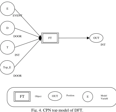
Fig. 4. CPN top model of DFT.
The parameters of DFT are input into top model to accurately describe the structure of the whole DFT. Basic events and gates are numbered from bottom to top and from left and right according to level and priority, and operate accordingly in the process of simulation. The top model is as shown in Fig. 4.
19
18
16 17
11 3 12
1 2 4 5
14
6 7
6 7
13 WSP
FDEP
8 9
15
Fig. 5. Dynamic fault tree of a satellite-based fault-tolerant electronic system.
In Fig. 4, the object is a special type of change and represents all the lower levels of model. Model variable [10] is a special position of CPN, which is used to describe the DFT by parameters. The whole DFT can be used to describe basic event, gate and top event. The positions in top model are described in Table I:
Model
Variable Type Description
E EVENT All basic events in DFT, including fault rate D DOOR All gates in DFT, including gate input T INT System work time described in DFT Top_E DOOR Gate caused by top event in DFT
OUT INT Input of simulation result, which is 1 for top event, or 00
Description of CPN Model
Variable Initial Model Variable
Basic Event (E)
1`(1,BE,[],WORK,30000,0)++ 1`(2,BE,[],WORK,10000,0)++ 1`(3, BE,[], WORK, 20000,0)++ 1`(4,BE,[], WORK,20000, 0)++ 1`(5,BE,[], WORK,40000,0)++ 1`(6,BE,[],WORK,6,0)++ 1`(7,BE,[], WORK,6,0)++ 1`(8,BE,[], WORK,2,0)++ 1`(9,BE,[], WORK,9,0)
Door (D)
1`(11,OR,[1,2],WORK)++ 1`(12,OR,[4,5], WORK)++ 1`(13, SPARE, [6,7], WORK)++ 1`(14,OR,[8,9],WORK)++ 1`(15, FDEP,[14,6,7], WORK)++ 1`(16,AND,[11,3,12],WORK)++ 1`(17,OR, [13,15], WORK)++ 1`(18,OR, [16,17], WORK)
Top Event (Top_E) 1`(18,OR,[16,17],FAULT)
Working Hours (h) 100
The second level of model determines the step length of simulation, which determines the simulation precision of the whole model on one hand. On the other hand, basic events and gates are listed according to their numbers. These lists are provided to conveniently judge all kinds of time dependent gates.
The third level of model judges whether any fault happens to basic event within a single step length of simulation. If any basic event in the fault is the input of spare gate, the basic event is added to the fault event list, and then it is also necessary to delete such basic event from spare event list. If it is not the input of spare gate, it should be added to the fault event list. After all basic events have been judged, the fault event list and spare event list are updated to enter the next level of model.
The fourth level of model judges whether any fault happens to gate. Firstly, gates are processed according to the type of gate. After all gates are judged, if top event happens, the last output is generated. Otherwise, gate judgment cycle exits and new one-step simulation is restarted.
IV. CASE STUDY
This paper employs the case in Reference [11]. The dynamic fault tree of a satellite-based fault-tolerant electronic system is presented in Fig. 5.
The reliability data of each basic event are presented in Table II.
No. Fault
Rate No. Fault Rate No. Fault Rate
1 0.3 4 0.2 7 0.00006
2 0.1 5 0.4 8 0.00002
3 0.2 6 0.00006 9 0.00009
In the process of modeling, it is necessary to firstly take the parameters of DFT as model input. According to the definition of each color set, the DFT is presented by
TABLE I: DESCRIPTION OF MODEL VARIABLES IN CPN TOP MODEL OF DFT
TABLE III: INITIAL VALUE OF MODEL VARIABLE IN THE CASE
parameters in Table III.
As CPN TOOLS has no floating color set, model variables are described by integers to describe the fault rate of basic event. However, actual fault rate isrand1/100000. Therefore, the corresponding random numbers are taken within [0, 100000].
Assuming that time step is 1h, after 100,000 model operations, 4,735 top events are found. Thus, the occurrence probability of top event is 0.0474. The result is consistent with Reference [11], so as to verify the accuracy of model constructed in this paper.
V. CONCLUSION AND FUTURE RESEARCH
The analysis and computation of DFT is an indispensable link of reliability analysis process in the dynamic system, while the computational process of existing analysis algorithm based on BDD and Markov chain is very complex and subject to the problem of state space explosion. However, simulation method is defected for trivial modeling process and difficulty to master by model builder. Hence, this paper firstly analyzes the characteristics of DFT primitives and provides the corresponding formal description. Moreover, a general simulation model based on CPN TOOLS is constructed to provide a convenient solution for DFT model.
REFERENCES
[1] G. Y. Chen, X. Z. Huang, and X. W. Tang, “Modular solutions for fault tree analysis of reliability of systems,” Journal of University of Electronic Science and Technology of China, vol. 35, pp. 989-992, June 2006.
[2] Z. F. Zhu, C. F. Li, E. S. He et al., “The dynamic fault tree analysis method based on markov chain,” ACTA Armamentarii, vol. 29, pp. 1104-1107, September 2008.
[3] R. Gulati and J. B. Dugan, “A modular approach for analyzing static and dynamic fault trees,” presented at the confenrece of Annual Reliability and Maintainability Symposium, 1997.
[4] V. Volovoi, “Modeling of system reliability Petri nets with aging tokens,” Reliability Engineering and System Safety, vol. 84, pp. 149-161, June 2004.
[5] B. Hichem, C. Pepijn, and S. Marielle, “Dynamic fault tree analysis using input/output interactive markov chains,” presented at the conference of Dependable Systems and Networks, 2007.
[6] D. Salvatore and P. Antonio, “Dependability evaluation with dynamic reliability block diagrams and dynamic fault trees,” IEEE Transactions on Dependable And Secure Computing, vol. 6, pp. 4-17, Jan. 2009.
[8] B. Hichem, C. Pepijn, and S. Marielle, “A compositional semantics for dynamic fault trees in terms of interactive markov chains,” presented at ATVA 2007, 2007.
[9] C. Y. Yuan, Theory and Application of Petri Nets, Beijing: Publishing House of Electronics Industry, 2005.
[10] C. H. Yang,, X. Liu, H. H. Chen et al., “Research on the simulation of task-oriented agile command and control organization in dynamic mission environment,” Journal of System Simulation, vol. 21, pp. 9-14, Jan. 2009
[7] C. H. Yang, J. J. Yang, and L. Yao, “General model for PMS reliability,” Journal of Beijing University of Aeronautics and Astronautic, vol. 37, pp. 1562- 1568, Dec. 2011.
[11] C. Zhang, C. B. Ma, D. Songet al., “Built-in test diagnosis strategy design for fault-tolerant system based on dynamic fault tree analysis,” ACTA Armamentarii, vol. 29, pp. 602-607, May 2008.
C. H. Yang was born in China in 1980. He received
his Ph.D. in management science and engineering from National University of Defense Technology, Changsha, China in 2008. Dr. Yang is currently a lecturer of Department of Management Science at Naval University of Engineering. He has performed and directed research on the development and application of reliability analyses of complex systems.
.
L. Yaowas born in China in 1979. He received his