Simulation of Three Phase Soft Starter using Multiple
SCRS
Arjun Sharma, Lecturer (SG), Department of Mechatronics,
Advanced Technical training Centre, Bardang, Sikkim-737134.
ABSTRACT
Motor Soft starter is typically used to control high starting current flowing by the induction motor. The control division of motor soft starter is prepared with more than two set of SCR coupled back to back in similar. A motor soft starter is a machine used with AC electrical motors to provisionally decrease the load and torque in the power train and electric current surge of the motor during start-up. In this paper, represents a motor soft starter using only multiple SCRs. The thyristor is a soft starter, its decreases the dimension, density & reduce the amount of SCR. Simulation result of future topology is compared with the conventional topology.
Keywords: Soft starter, induction motor, two phase control, torque pulsation.
1. INTRODUCTION
Induction motor is usually used in industrial as well as household applications. Soft starter is use for dropping high starting current as well as torque pulsation. In commercially available soft starter, a
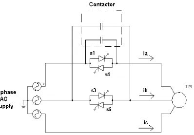
three-phase bypass contactor is typically connected in similar with the end-to-end SCR of every phase. The principle of this three-phase contactor is to reduce any more thermal pressure and control loss forced on the SCR after completion of the starting transient of the motor. When the motor reaches its full speed and rated current, the contactor will be pulled into bypass these SCRs. During this time, all the SCRs will be in their turned off state and the motor will be straight animated from the grid throughout the bypass contactors. Fig 1 shows schematic of conventional soft starter with bypass contactor.
Fig.1. schematic of conventional soft starter
This firing angle profile is set by the consumer based on the first setting of the locked-rotor torque (LRT) and the ramp time, a simple illustration of which is shown in Fig 2.
Fig.2. Voltage ramp profiles.
The LRT is the initial starting torque that is necessary to increase speed the motor through starting, and the slope time is the time it takes for the voltage to go from the initial voltage value at the
LRT setting to the highest full voltage that is being applied to the motor. By adjusting the slope time, the rushing time of the motor can be controlled. consequently, the firing angle which controls the quantity of applied motor voltage is reduced increasingly depending on the slope time during the period of starting until the motor has reached its full speed and rated current, where upon the contactors are closed to bypass the SCRs.
2. PROPOSED TOPOLOGY
Fig.3. Schematic of two phase controlled three phase soft starter
In this category of electronic soft starter any two phases can be prohibited. The category is R and Y phase, Y and B phase or R and Y phase. R and Y phase controlled soft starter is shown in Fig. 3. In R and Y phase controlled soft starter, R phase consist of high current than the Y phase when motor runs in onward way because of unstable voltage supplied to the motor. Table 1 shows Relation between current flows in motor and controlled strategy. Soft starters can be any control system that reduces the torque by temporarily reducing the voltage or current input, or a device alters how the motor is linked in the electric path. In soft starter all phase are prohibited and accordingly evenhanded voltage is apply to the cruise while in upcoming topology, one phase is straight linked to the soft starter and unbalance voltage is supplied to the motor. While unstable voltage, unbalanced current flow right through the unequal current, unstable thermal pressure is applied to the SCRs of prohibited phase. Extra it increases the harmonic content and optionally still turned into an additional current part of the current. This turn causes an unbalanced power allocation within the load. In an electric motor overload occurs thereby increased torque variation. It can damage device as well as motor.
3. CONTROL STRATEGY
In this strategy as unbalanced voltage supply is apply to the motor, current flowing throughout it is also unbalanced. To manage the unequal current require to apply firing position α with a remedial position Δα. The nonstop monotonic function between fixed starting and ending points is interpreted as a purpose of the load to be prohibited. The purpose is first empirically single-minded by reproduction process. In this system remedial position is additional with the firing position of phase which contains high current while corrective position is subtracted from the firing position of phase which contains a lesser amount of current. Corrective position can be finding out by equating voltage at motor load. By try and error method we are able to find out the range for the corrective position. The corrective position varies in range of 0˚ to 30˚. At firing angle (α) 0˚ to 60°, a corrective position Δα = 0˚ while at firing position (α) 150° to 180˚, Δα = 30˚. The graph for corrective position Δα is shown in Fig. 4.
Fig.4.Variation of corrective position with firing position.
In open loop control current pounding is happen. Closed loop control is necessary to keep away from these current pulsations. For closed loop, voltage across SCR is in use as feedback. Power factor of motor is rapidly reduces when alteration takes place from alteration phase to normal run phase. Since this current pounding arises. Zero crossing of current find out by taking voltage across SCR as response. Current pounding is avoided by applying firing position from zero crossing of current as an alternative of voltage. Bypass contactor is also linked in similar with the starter. Bypass contactor is operated when slope up time is finished and motor get accelerated. Through bypass phase starter is disjointed from the motor and supply is straightly linked to the motor. Since bypass contactor fatalities are decrease as SCRs are bypassed.
4. SIMULATION RESULTS
Model result on motor initial presentation of conventional & proposed scheme were obtained for a 60hp, 440V, four-pole, three phase asynchronous cruise, two simulation processes were acquired that is: 1) conventional result; 2) proposed result with proposed control.
The three phase conventional soft starter was first pretend. The results of the three phase motor currents are shown in Fig 5. As one can examine there in, the motor currents have smooth starting profiles as the firing position is falling, with low starting currents. Here current in all three phases are equivalent though current in proposed result with conventional control approach has imbalanced current. To balance this current, corrective position is added or subtracted to the firing position which leads to equivalent voltage supply which results in a impartial current. As may be seen in Fig 6, the three phase motor currents have practically smooth starting profiles, which specify important starting passing development than the conventional control. In this result current in uncontrolled phase is slightly higher than the current in controlled phase. Once normal speed is achieved, soft starter gets disjointed from the supply while bypass contactor connects power supply to the motor. It reduces losses of the circuit as SCR are bypassed.
The developed motor torque summary for conventional starter is represented in Fig 7. Again, a smooth initial summary with smallest amount torque pounding. An improved initial torque summary for the proposed approach is showed in Fig 8. It can be seen from the figures that the starting transient torque pounding for both the topology is almost similar.
Fig.6. Motor current in proposed topology.
Fig.7. Motor torque developed by conventional soft starter
Fig.8. Motor torque developed by proposed soft starter.
CONCLUSION
REFERENCES
[1] W. Shephered and J. Stanway, “The poly phase induction motor control by firing angle adjustment of silicon controlled rectifiers,” IEEE International Convention Record, pp, 135-154, 1964.
[2] W. Shephered, “ On the analysis of the three phase induction motor with voltage control by thyristor switching,” IEEE Transaction on Industry and general Application, Vol, IGA-4, pp, 304-311, May/Jun 1968.
[3] C. B. Jacobina, R. L. de A. Ribeiro, A. M. N. Lima, and E. R. C. da Silva, “Fault- tolerant reversible AC motor drive system,” IEEE Transactions on Industry Applications, Vol. 39, No. 4, pp. 1077-1084, Jul/Aug 2003.
[4] G. Zenginobuz, I. Cadirci, M. Ermis, and C. Barlak, “Soft starting of large induction motors at constant current with minimized starting torque pulsations,” IEEE Transactions on Industry Applications, Vol. 37, Issue 5, pp. 1334-1347, Sep/Oct 2001
[5] A. M. S. Mendes and A. J. M. Cardoso, “Fault-tolerant operating strategies applied to three-phase induction-motor drives,” IEEE Transactions on Industrial Electronics, Vol. 53, No. 6, pp. 1807-1817, Dec. 2006.
[6] M. B.de R Corrêa, C. B. Jacobina, E. R. C. da Silva, and A. M. N. Lima, “An Induction motor drive system with improved fault tolerance,” IEEE Transactions on Industry Applications, Vol. 37, No. 3, pp. 873-879, May/Jun 2001.
[7] Huang, et al.., “ESD protection design for advanced CMOS,” in Proc. SPIE, 2001, pp. 123-131
.
[8] S. P. Bingulac, “On the compatibility of adaptive controllers (Published Conference Proceedings style),” in Proc. 4th Annu. Allerton Conf.Circuits and Systems Theory, New York, 1994, pp. 8–16.
[9] M. -D. Ker; C. -Y. Wu, T. Cheng, M. J. -N. Wu, T. -L. Yu, and A.C. Wang, “WholechipESD protection for CMOS VLSI/ULSI with multiple power pins,” Proc. of theInt.Integrated Reliability Workshop, pp. 124–128, 1994.
[10] C. Russ, M. Mergens, J. Armer, p. jozwiak, G. Kolluri, L. Avery, and K. Verhaege, “GGSCRs: GGNMOS triggered silicon controlled rectifiers for ESD protection in deep submicron CMOS processes,” in Proc.EOS/ESD Symp., 2001, pp.22-31.
[11] M.-D. Ker and K.-C. Hsu, “overview of on-chip electrostatic discharge protection design with SCR-vased devices in CMOS intergrated circuits,” IEEE Tran. Device Mater. Reliab. Vol. 5, no. 2, Jun 2005, pp.235-249
.
[12] P.-Y.Tan, M. Indrajit, p.-H. Li, and S.H.Voldman, “Rc-triggered PNP and NPN simultaneously switched silicon controlled rectifier ESD networks for sub-0.18um technology,” in Proc. Of IEEE Int. Symp. On Physicaland Failure Analysis of Integrated Circuits, 2005, pp. 71-75.