Published online October 20, 2014 (http://www.sciencepublishinggroup.com/j/ijmsa) doi: 10.11648/j.ijmsa.20140306.16
ISSN: 2327-2635 (Print); ISSN: 2327-2643 (Online)
Thickness dependency of CuO Nanocoating layer on
thermal performance of HPHE
Aysar Abd Alrazaq Alamery, Hussein Ali Jawad, Zainab Fadhil Mahdi
*Institute of Laser for Postgraduate Studies, University of Baghdad, Jadriha, P. O. Box 47314 Baghdad, Iraq
Email address:
[email protected] (A. A. A. Alamery), [email protected] (H. A. Jawad), [email protected] (Z. F. Mahdi)
To cite this article:
Aysar Abd Alrazaq Alamery, Hussein Ali Jawad, Zainab Fadhil Mahdi. Thickness Dependency of CuO Nanocoating Layer on Thermal Performance of HPHE. International Journal of Materials Science and Applications. Vol. 3, No. 6, 2014, pp. 314-320.
doi: 10.11648/j.ijmsa.20140306.16
Abstract:
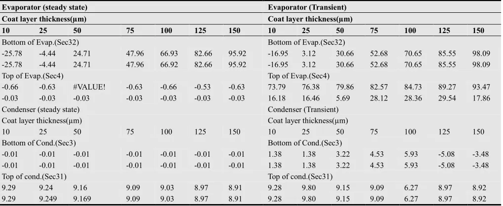
Among the different passive techniques present, surface coating seems to the most effective one. Copper oxide-based materials are of interest on account of their potential uses in many technological fields. Modeling of the nanocoating on fins in Thermosyphon heat exchangers using ANSYS software is introduced. The temperature distribution was investigated. Seven thicknesses of CuO coating layers are used on fins of HPHE with the aim of improving working system. The enhancement is proportioning with the increment in coat thickness at the evaporator section of transient conditions (-16.95, 3.12, 30.66, 52.68, 70.65, 85.55and 98.09) for (10, 25, 50, 75, 100,125and150 µm) thicknesses respectively. From these results, maximum enhancement occurred at150 µm coat. Coat process of the evaporator fins can give fast response of nanofluid to absorb the latent heat from the outdoor air and vaporize to start the closed cycle working system so the increasing in the energy saving is investigated.Keywords:
HVAC, HPHE, ANSYS, Coating Layer Thickness, Copper Oxide, Temperature Distribution1. Introduction
Due to the human need for energy, a more efficient way of using it is a major challenge in the scientific community. The performance of heat transfer is one the most important parts of these types of investigation [1].Heat pipe technology has found increasing applications in enhancing the thermal performance of heat exchangers in microelectronics, energy saving in HVACs[2].Heat transfer enhancement is an extensive research area, in order to increase the efficiency of energy management. There are several ways to enhance heat transfer characteristics, which can be mainly classified into active and passive techniques. Active techniques rely on external power source, such as electronic or acoustic fields and surface vibration. Most of the active techniques are abstruse and intractable with the surrounding, while passive techniques include surface coating, intrinsic fins, surface roughness and change of nano fluids. The passive techniques help us to overcome the limitations faced by the active techniques [3].HP is essentially a passive heat transfer device with an extremely high effective thermal conductivity .The two-phase heat transfer mechanism results in heat transfer capabilities from one hundred to several thousand times that of an equivalent piece of copper [4, 5].
Among the different passive techniques present, surface coating seems to the most effective one. Surface coating can be macro structured micro structured and nanostructured coatings [3].H.A. Mohammed and K. Narrein. [6] numerically investigated the effects of using different geometrical parameters with the combination of nanofluid on heat transfer and fluid flow characteristics in a helically coiled tube heat exchanger (HCTHE).P.G. Anjankar and R.B.Yarasu.[7]studied the new design and thermal performance of Thermosyphon . W.Srimuanget al. [8] presented the knowledge of two-phase closed Thermosyphon (TPCT) as being used nowadays and the application of TPCT to air to air heat exchanger.
Symbols
HVACs= Heating, Ventilation and Air conditioning systems.
K= Thermal Conductivity (W.m-1K-1) Cp= Specific Heat (J.kg-1K-1)
ρ= Density (kg.m-3) DBT=Dry bulb temperature WBT=Wet bulb temperature h = Convection coefficient.
HPHE = heat pipe heat exchanger HP=heat pipe
T = Absolute temperature.
2. Modeling of Heat Pipe Heat
Exchanger
The heat pipe were constructed in ANSYS Preprocessor package [9].The top and bottom layers are represented by the coating, Seven thicknesses of CuO coating layers are used (10, 25, 50, 75, 100,125and 150) on fins in heat pipe were used respectively. These layers thickness are used in coating with the aim of improving the thermal properties of the base metal (aluminum).
3. Boundary Conditions
The boundary conditions of the tube is used as temperature distribution along HP which can be obtained by phase change properties from nanofluid in evaporator section to the vapor in the condenser section [10].Boundary conditions of the thermal model were specified as surface loads through ANSYS codes [9,11].Figures(1,2)show counter-flow HPHE for effectiveness ratings and Schematic diagram for the experimental set-up.
Fig (1). Schematic of the counter-flow HPHE for effectiveness ratings .
4. Results and Discussion
After all the data [Al fins with thickness of 0.4mm and properties (K= 237 W.m-1K-1, Cp=905 J.kg-1K-1, ρ=2707
kg.m-3), Cu HP with properties (K=398 W.m-1K-1, Cp=384
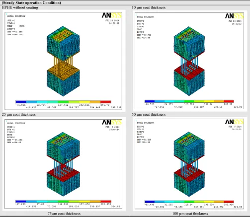
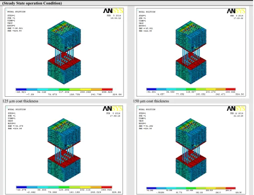
J.kg-1K-1, ρ=8954kg.m-3) [12], Variation thickness of coat layers, Fixed boundary conditions as mentioned above] were presented. For all tested fins, two fixed positions were taken in evaporator and condenser fins according to the direction of air flow. The results which approach from the ANSYS program after modeling the heat pipe and run the program can show in Table (1). From figures, the response of the system in transient conditions is clear compared with steady state. HPHE works better with the change of the thickness of coat layer as increasing. In the yellow area of this table (125and 150 µm coat thickness),obvious response of the nanofluid inside HP to absorb large amount of heat from
fresh air and vaporizing ,the coil entering air temperature decrease which is shown in the nellie color of the fins in the outside of the evaporator section. When the air reaches the inlet side of the condenser section it will be very cold due to the effect of cooling coil and this can be shown in the nellie color of these fins .Nanofluid reaches the condenser section in vaporization state, the heat transfer due to the second law of thermodynamic from the high temperature media to the low temperature media [12] .Very cold air can absorb the heat from the vaporize nanofluid and become warmer which is suitable for the conditioned space. This can be shown in the green color of condenser fins in outside of this section. In conventional systems for this purpose, external energy such as electric energy is used [2]. The evaporator of HPHE functions as the air pre-cooler before cooling coil and the condenser of HPHE functions as the air reheat before electric coil in HVACs.
Table (1.a). Results approach from the ANSYS program after modeling the heat pipe. (Steady State operation Condition)
(Steady State operation Condition)
HPHE without coating 10 µm coat thickness
25 µm coat thickness 50 µm coat thickness
(Steady State operation Condition)
125 µm coat thickness 150 µm coat thickness
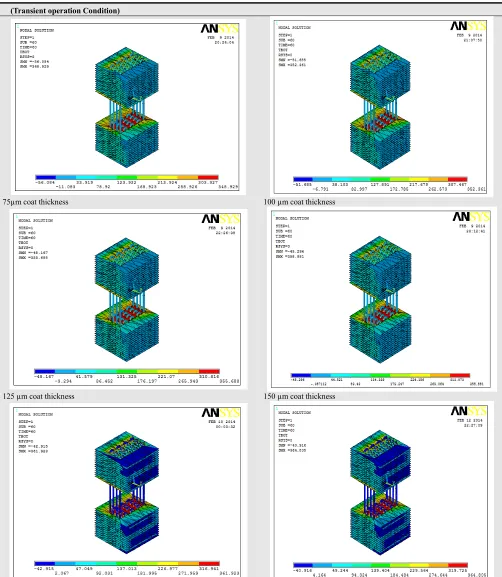
Table (1.b). Results approach from the ANSYS program after modeling the heat pipe. (Transient operation Condition)
(Transient operation Condition)
HPHE without coating 10 µm coat thickness
(Transient operation Condition)
75µm coat thickness 100 µm coat thickness
125 µm coat thickness 150 µm coat thickness
The temperatures distribution in two positions for each fin in bottom and top of each evaporator and condenser sections for steady and transient operation conditions are listed in table (2).
After calculations of the percentages of thermal performance enhancement with nanocoating layers by using the equation ((Without Nanocoat-With Nanocoat)/ (Without
Table (2). Temperatures distribution results which approach from running ANSYS program after the modeling heat pipe with all operation conditions.
Steady state conditions of operation
Positions/Sec32 Al pure Coat layer thickness(µm)
10 25 50 75 100 125 150
1 -14.2 -17.86 -14.83 -10.69 -7.39 -4.69 -2.46 -0.58
2 -14.2 -17.86 -14.83 -10.69 -7.39 -4.69 -2.46 -0.58
Positions/Sec4
1 321.35 323.47 323.36 323. 47 323.35 323.47 323.039 323.36
2 323.57 323.68 323.68 323.68 323.68 323.68 323.679 323.68
Positions/Sec3
1 297.96 297.98 297.98 297.98 297.98 297.98 297.976 297.98
2 297.96 297.98 297.98 297.98 297.98 297.98 297.976 297.98
Positions/Sec31
1 287.07 260.39 260.54 260.77 260.98 261.16 261.326 261.48
2 287.07 260.39 260.54 260.77 260.98 261.16 261.326 261.48
Transient conditions of operation
Positions Al pure Coat layer thickness(µm)
10 25 50 75 100 125 150
Sec32
1 -14.2 -16.608 -13.757 -9.846 -6.719 -4.17 -2.051 -0.27
2 -14.2 -16.608 -13.757 -9.846 -6.719 -4.17 -2.051 -0.27
Sec4
1 260.14 68.173 61.431 52.383 45.335 39.72 27.908 16.98
2 302.96 253.95 253.09 285.7 217.75 217.03 213.472 248.86
Sec3
1 279.87 276.01 274.22 270.87 267.19 263.27 294.095 289.61
2 279.87 276.01 274.22 270.87 267.19 263.27 294.095 289.61
Sec31
1 287.07 260.44 258.93 260.79 260.98 269.06 261.324 261.47
2 287.07 260.44 258.93 260.79 260.98 269.06 261.324 261.47
Table (3). Percentages of thermal performance enhancement with different CuO Coating layers thickness
Evaporator (steady state) Evaporator (Transient)
Coat layer thickness(µm) Coat layer thickness(µm)
10 25 50 75 100 125 150 10 25 50 75 100 125 150
Bottom of Evap.(Sec32) Bottom of Evap.(Sec32)
-25.78 -4.44 24.71 47.96 66.93 82.66 95.92 -16.95 3.12 30.66 52.68 70.65 85.55 98.09
-25.78 -4.44 24.71 47.96 66.92 82.66 95.92 -16.95 3.12 30.66 52.68 70.65 85.55 98.09
Top of Evap.(Sec4) Top of Evap.(Sec4)
-0.66 -0.63 #VALUE! -0.63 -0.66 -0.53 -0.63 73.79 76.38 79.86 82.57 84.73 89.27 93.47
-0.03 -0.03 -0.03 -0.03 -0.03 -0.03 -0.03 16.18 16.46 5.69 28.12 28.36 29.54 17.86
Condenser (steady state) Condenser (Transient)
Coat layer thickness(µm) Coat layer thickness(µm)
10 25 50 75 100 125 150 10 25 50 75 100 125 150
Bottom of Cond.(Sec3) Bottom of Cond.(Sec3)
-0.01 -0.01 -0.01 -0.01 -0.01 -0.01 -0.01 1.38 1.38 3.22 4.53 5.93 -5.08 -3.48
-0.01 -0.01 -0.01 -0.01 -0.01 -0.01 -0.01 1.38 1.38 3.22 4.53 5.93 -5.08 -3.48
Top of cond.(Sec31) Top of cond.(Sec31)
9.29 9.24 9.16 9.09 9.03 8.97 8.91 9.28 9.80 9.15 9.09 6.27 8.97 8.92
9.29 9.249 9.169 9.09 9.03 8.97 8.91 9.28 9.80 9.15 9.09 6.27 8.97 8.92
5. Conclusions
One of the most advanced methods to improve the thermal conductivity of heat pipes is coat the fins by nonomaterial. The recent advances in the field of micro and nanotechnology have led to the development of efficient methods for heat transfer enhancement using nano-fins which are expected to give unique heat transfer potential and more
vaporize to start the closed cycle for working the system so the increment in the energy saving is investigated which is the more important in HVACs.
References
[1] H. Mirshahi, M. Rahimi,"Experimental Study on the Effect of Heat Loads, Fill Ratio and Extra Volume on Performance of a Partial-Vacuumed Thermosyphon",Iranian Journal of Chemical Engineering ,Vol. 6, No. 4 (Autumn), 2009, IAChE.
[2] E. Firouzfar, M. Soltanieh, S. H. Noie,M. H. Saidi,"Investigation of heat pipe heat exchanger effectiveness and energy saving in air conditioning systems using silver nanofluid",Int. J. Environ. Sci. Technol., 2012, 9:587–594.
[3] S. Kumar C. S, S. Suresh and Rajiv K,"Heat Transfer Enhancement by Nano StructuredCarbon Nanotube Coating", International Journal of Scientific & Engineering Research Volume 3, Issue 6,June-2012, ISSN 2229-5518.
[4] A. Khare,A. Paul andG. Selokar,"Design Development of Test-Rig to Evaluate Performance of Heat Pipes in Cooling of PrintedCircuit Boards",VSRD-MAP, Vol. 1 (2), 2011, 65-79.
[5] M. Shafahi, V. Bianco,K. Vafai and O. Manca,"Thermal performance of flat-shaped heat pipes using nanofluids",International Journal of Heat and Mass Transfer 53 ,2010, 1438–1445.
[6] H.A. Mohammed and K. Narrein,"Thermal and hydraulic characteristics of nanofluidflow in a helically coiled tube heat exchanger",International Communications in Heat and Mass Transfer 39 2012, 1375–1383.
[7] P.G. Anjankar and R.B.Yarasu,"Experimental Analysis of Condenser Length Effect on thePerformance of Thermosyphon", International Journal of Emerging Technology and Advanced Engineering, Volume 2, Issue 3, March 2012, ISSN 2250-2459.
[8] W. Srimuang1,P.Khantikomol and P. Amtachaya," Two Phase Closed Thermosyphon (TPCT) andit’sapplication for an Air-to-air Heat Exchanger", The Journal of KMUTNB., Vol. 22, No. 1, Jan. - Apr. 2012.
[9] A. A. Alamery, H. A. Jawad, H. A. Ameen and Z.F. Mahdi," Effect of Hard Materials Nanocoating on Fins in (Thermosyphon) HPHE with Nano Working Fluid",IJERT , Volume. 3, Issue. 06, June – 2014.
[10] S.H. Noie, S. ZeinaliHeris, M. Kahani and S.M. Nowee," Heat transfer enhancement using Al2O3/water nanofluid in a
two-phase closed Thermosyphon ", International Journal of Heat and Fluid Flow 30, 2009, pp.700–705.
[11] Y.H. Yau," Experimental thermal performance study of an inclined heat pipe heat exchanger operating in high humid tropical HVAC systems", International Journal of Refrigeration 30 ,2007, 1143-1152.
![Fig (2). Schematic diagram for the experimental set-up [2].](https://thumb-us.123doks.com/thumbv2/123dok_us/8470379.1711092/2.595.118.489.252.518/fig-schematic-diagram-experimental-set.webp)